

Page 1
MALONE
R
MALONE
R
*ATTENTION CUSTOMERS*
Thank you for your recent purchase of a Malone trailer.
Please inspect all parts and hardware bags prior to assembly.
**Set the large red envelope (in the axle box) containing important
documents pertaining to registering your trailer in a safe spot.
If you encounter any missing components please contact us at:
Email:technical@maloneautoracks.com
OR
Phone:(207) 774 - 9100 X215
Business Hours: Monday-Friday
9am- 5pm
Thank you from all of us at Malone
MPG525
Page 2

MALONE
R
Important Note
Product Warranty & Registration Form
All information is condential and used exclusively by MALONE only.
Dear Customer,
Thank you for your purchase of a Malone Product.
In order to be eligible for the Malone Warranty program, we ask that you contact us by email or
online at one of the following: With-in 30 days of purchase. You can also mail this letter back to the address at
the bottom.
• Online: www.maloneautoracks.com
• Email: Technical@maloneautoracks.com
We will require the information below.
Here is the information collected:
First Name:
Last Name:
Address:
Address2:
City:
State:
Zip:
Country:
Email:
Phone:
Product Description/Name:
Product MPG# or Serial #
Date Purchased:
Store Where Purchased:
Purchase Price:
Thank you for choosing Malone!
81 County Rd. Ste 1, Westbrook, ME 04092
P: 207.774.9100 F: 207.615.0551
E: sales@maloneautoracks.com W: www.maloneautoracks.com
Page 3
MPG460XT
Take a few moments and read through these instructions to familiarize yourself
with the step by step assembly process before you begin turning wrenches.
Unpack and sort the components into groups as shown in the following pages.
Then assemble each group in order. Lets get started !!
Required Tools:
• (2) 3/4” wrenches • (2) 9/16” wrenches (a deep socket is recommended)
• Large fl at blade screw driver • (1) 7/16” wrench
• Razor knife • Pliers
• Wire stripping tool • Electrical connector crimping tool
• Lug wrench • Small hammer
Malone MicroSport Trailer
Model MPG460XT Assembly Instructions
TM
REV 2
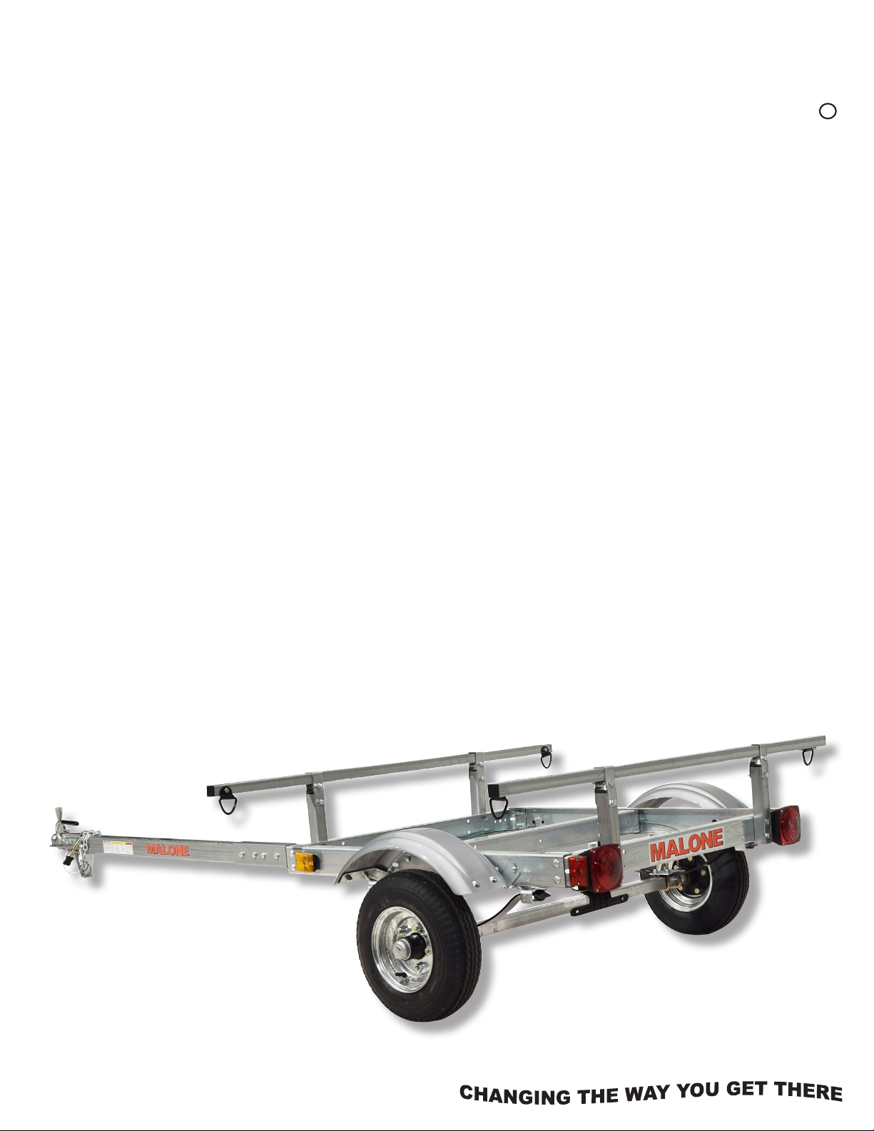
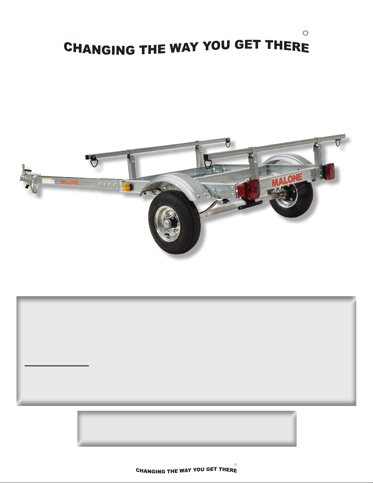
Malone XtraLightTM Trailer
MALONE
MALONE
Model MPG525G Assembly Instructions
MPG525G
R
Take a few moments and read through these instructions to familiarize yourself with the
step by step assembly process before you begin turning wrenches.
Unpack and sort the components into groups as shown in the following pages.
Required Tools:
• (2) 3/4” wrenches • (2) 9/16” wrenches (a deep socket is recommended)
• Large at blade screw driver • 7/16” wrench • 3/8” wrench and socket
Then assemble each group in order. Lets get started !!
• Large Phillips head screw driver • Rubber hammer
Visit us at maloneautoracks.com
for more fi ne products and accessories.
technical@maloneautoracks.com
800-295-0042 ext. 215
1
R
Page 4
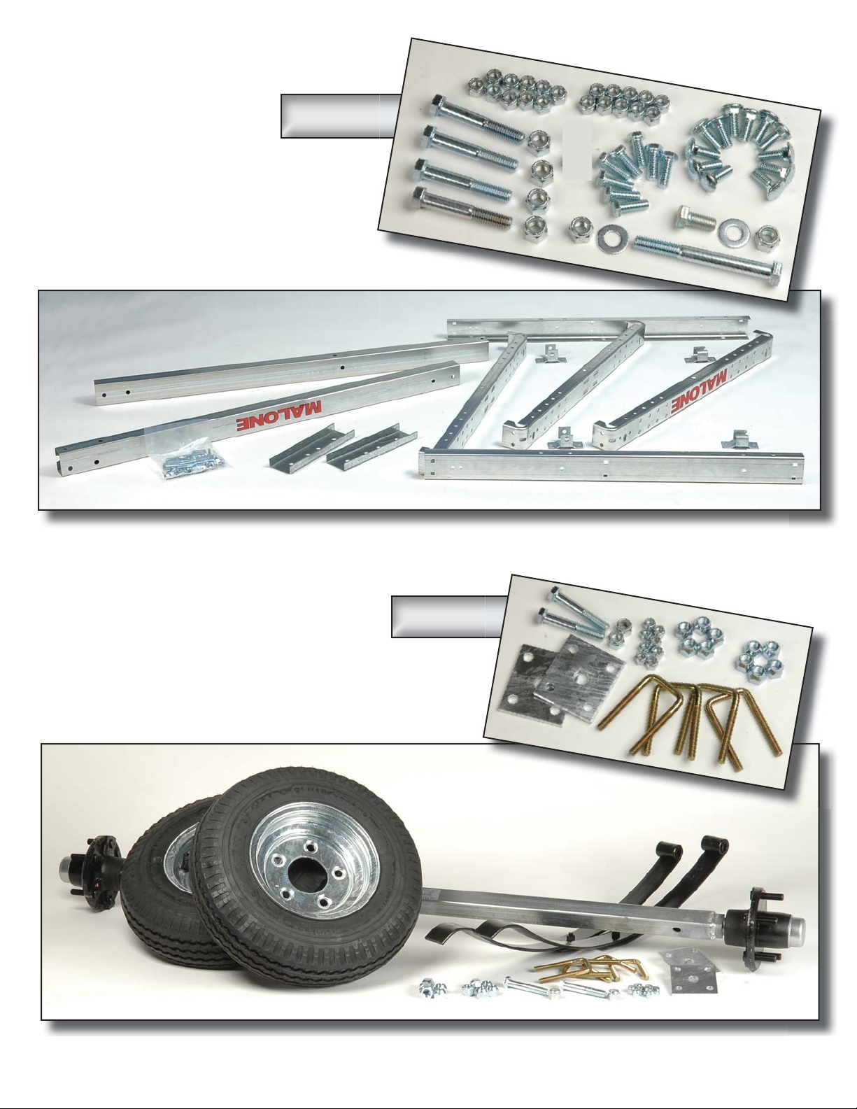
MPG525G
Group 1:
Frame
Components
Bag 11430
Group 2:
Axle / Spring Components
Bag 11432
Visit www.maloneautoracks.com/Replacement-Parts
for all of your spare part needs
Page 5

Group 3:
MPG460G
COUPLER ASSEMBLY
(Group 5)
Group 3: Lighting Components
MPG525G
Lighting
Components
Group 4: Fender Components
Bag 11468
Group 5: Coupler Components
Bag 11431
Bag 11494
Visit www.maloneautoracks.com/Replacement-Parts
for all of your spare part needs
Page 6
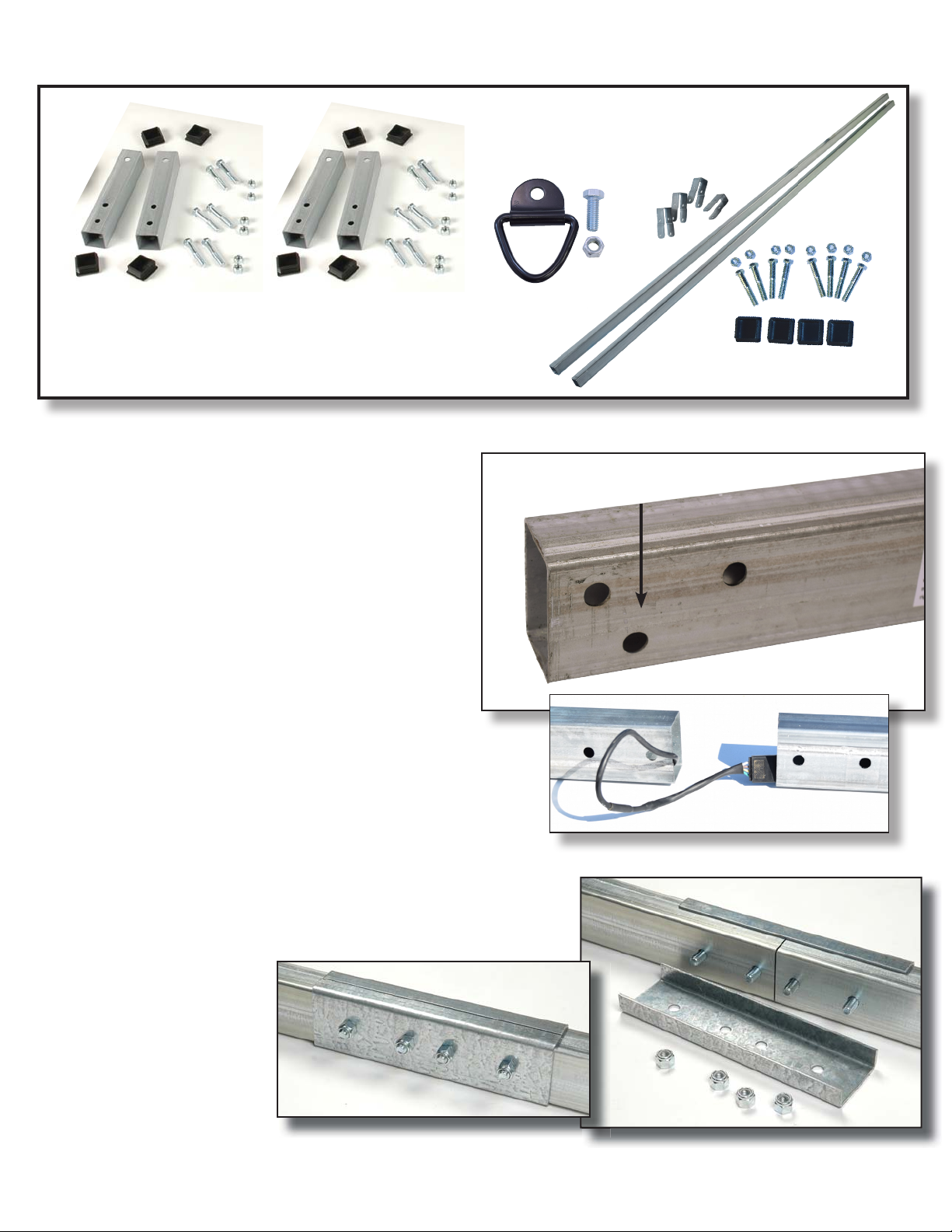
Bag 11433
Bag 11433
Group 6: Load Bar Components
Load Bars Support Tubes (4)
TONGUE & FRAME ASSEMBLY (Group 1)
1. First we will build the 2 piece tongue. The middle
of the tongue has symmetrical holes for the joining
plates, and You can identify the hitch end of the
tongue by the 3 holes on the left (drivers) side for
the coupler.
2. Align the tongue half’s together and insert the
wiring harness through both sections of the tongue,
making sure the plug end matches the
vehicles connection. The colored pigtails should
be towards the rear of the tongue.
D-Rings (4)
Load Bars (2) and Brackets (4)
Coupler / Hitch End
3. Being careful not to pinch the wiring harness,
square the tongue half ends together and install the
joining plates on each side. (Note the rear tongue
section is symmetrical so it works ne either way. It
has no top and bottom.) Fully tighten the 1/2” bolts
with two 3/4” wrenches.
Visit www.maloneautoracks.com/Replacement-Parts
technical@maloneautoracks.com
4 800-295-0042 ext. 215
for all of your spare part needs
Page 7
MPG525G
14. Being careful not to pinch the wiring harness, square
the tongue half ends together and install the joining plates
on each side. (Note
the rear tongue section
is symmetrical so it
works fi ne either way.
It has no top and
bottom.) Fully tighten
the 1/2” bolts with two
3/4” wrenches.
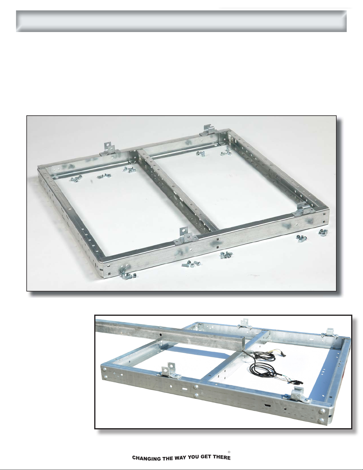
NOTE: We begin assembling the frame upside down, later we will fl ip it over to complete the assembly.
MALONE
4. Layout the frame components as shown, “upside down”.
(b) The tongue mounting holes in the middle of the front two cross members must face up.
(c) The MALONE decal is on the rear cross member and must be upside down.
(d) The mid-cross member must face the same way as the rear cross member.
(e) Spring hangers with shackle bolt holes to the front, slippers to the back.
(f) Carriage bolts to mount cross members to rails.
(g) Regular bolts to mount spring hanger brackets.
15. Layout the frame components as shown, “upside down”.
(a) The spring bracket mounting holes in the side rails must face up.
(b) The tongue mounting holes in the middle of the front two cross members must face up.
(c) The MALONE decal is on the rear cross member and must be upside down.
(d) The mid-cross member must face the same way as the rear cross member.
(e) Spring hangers with shackle bolt holes to the front, slippers to the back.
(f) Carriage bolts to mount cross members to rails.
(g) Regular bolts to mount spring hanger brackets.
(a) The spring bracket mounting holes in the side rails must face up.
a
e
a
d
d
b
b
c
a
e
a
g
5. Install all 12 carriage bolts, nger tighten only. Install all 8 spring hanger bolts with the nuts inside the
frame. Fully tighten the rear spring hangers. Finger tighten the front spring hangers.
6. Lay the tongue onto the
frame, with the MALONE
logo upside down.
Support the end of the
tongue so it lays nearly
at on the front and mid
cross members.
f
technical@maloneautoracks.com
800-295-0042 ext. 215
5
R
Page 8

MPG525G
17. Lay the tongue onto the frame, with the MALONE logo upside down. Support
the end of the tongue so it lays nearly fl at on the front and mid cross members.
18. Install the long 1/2” bolt through the front cross member, (washer under the bolt head), nut inside
the cross member
and fi nger tighten.
Install the short 1/2”
bolt inside the end of
the tongue, (washer
under the bolt head),
nut inside the cross
member and fi nger
tighten.
19. Fully tighten all
12 carriage bolts.
Then fully tighten
the two 1/2” tongue
mounting bolts.
7. Install the long 1/2” bolt through the front cross member, (washer under the bolt head), nut inside the
MALONE
cross member and nger tighten. Install the short 1/2” bolt inside the end of the tongue, (washer under the
bolt head), nut inside the cross member and nger tighten
8. Fully tighten all 12 carriage bolts. Then fully tighten the two 1/2” tongue mounting bolts.
SPRING AND AXLE ASSEMBLY
SPRING & AXLE ASSEMBLY (Group 2)
(Group 2)
1. Set the envelope containing the manufacturer’s certifi cate of
origin (MCO) and VIN labels aside in a safe place.
2. Find the side of the axle
with the spring centering
holes. These holes mate
with the spring center stud.
4. Run each nut down UNTIL IT NEARLY TOUCHES
THE PLATE ONLY! DON’T FULLY TIGHTEN NOW!!
You may need to wiggle the springs to fi t them into the
spring brackets in the next step.
6 800-295-0042 ext. 215
R
technical@maloneautoracks.com
Page 9

MPG525G
MALONE
5. Lift the axle/spring assembly to the trailer frame and slide the slipper spring ends into the slipper
spring brackets. Then let the spring eyes down into the front hangers.
6. Install the shackle bolts with the nuts to the inside and
tighten until fi rm. Do not over tighten which would bend
the spring hanger in and pinch the spring.
7. Fully tighten the 4 front spring hanger mounting bolts.
8. Fully and evenly tighten the 8 axle U-bolts.
9. Install the wheels on the hubs with
valve stems facing out and install and
fi nger tighten the lug nuts.
10. Lift the trailer at one rear corner
and roll it over onto the tires.
ALWAYS BEND FROM YOUR KNEES
WHEN LIFTING. IF THE TRAILER
IS TOO HEAVY FOR YOU TO FLIP
SAFELY RECRUIT SOME FRIENDS
TO ASSIST YOU.
11. Tighten the lug nuts fi rmly, to 75 to
85 foot pounds of torque.
technical@maloneautoracks.com
800-295-0042 ext. 215
7
R
Page 10

MPG525G
LIGHT ASSEMBLY (Group 3)
MALONE
L.E.D. REFERENCE:
Trailer Wiring Color Code
•Brown = running lights
•Yellow = left turn / left brake
•Green = right turn / right brake
•White = ground
1. Sandwich the license plate mounting bracket between the driver
side lamp and the frame. Push the wire leads through the center
hole and the lamp studs through the outer holes. Use the nuts
provided with the lamp kit.
2. Using the holes in the front corners
of the frames side rail, mount the amber
side lights. First, push the wire leads
through the outside holes and the lamp
stud through the center hole.
3. Secure with the lamp stud nut.
4. Starting at the end of the tongue, we will divide the wiring to both sides of the trailer and then again to the
running lights and the tail lights.
Looking at the end connections, route the GREEN/BROWN/WHITE wire along the passengers side. Route
the YELLOW/BROWN/WHITE along the drivers side as shown. These color coated wires should match the
connections at your lights.
5. With the wiring divided at the end of the tongue, use the
clips provided to secure the wire to the inside of the frame
channel as shown.
8 800-295-0042 ext. 215
R
technical@maloneautoracks.com
Page 11

MPG525G
7. Route the wires to the rear, through the middle cross
member and along the frame. Install wire clips to secure
the wires between the cross members.
9. Using your fi ngers, separate
about 1” of the ends of the
harness. Strip about 3/8” of
insulation off each wire to allow length for wrapping
around the stiff tail light wire.
8. Route the harness around
the corner and allow the same
length harness as the length
of the tail light wires. Triple
check that the wires are routed
where you want them. Cut the
harness.
10. Hold the color matching harness and tail light wires
together with the end of the stripped insulation even with
each other, then wrap the harness
wire clockwise around the tail lamp
wire completely covering it.
11. Screw a wire nut down over
each until fi rm. Then tuck the wire
into a frame clip as shown.
FENDER ASSEMBLY (Group 4)
6. Next, we’ll divide the wiring again. Direct the two(2) pigtailed end
MALONE
towards the side running lights up front along the frame, and then the
three(3) pigtailed end towards the rear tail lights.
7. Route the wires to the rear, through the middle cross member and
along the frame. Install wire clips to secure the wires between the
cross members. Repeat on the other side of the trailer.
8. With the wires routed all the
lights, rmly grasp the wiring
connections and plug-in matching
colored leads/wires.
Repeat with all remaining lights.
FENDER ASSEMBLY (Group 4)
1. Loosely install fender
mounting brackets as shown
so they can move to fi t the
fender. Use hex bolts with
the nuts inside the frame.
2. Install and fully tighten
fender. Use screws and nuts,
nuts inside fender.
3. Fully tighten fender mounting brackets.
technical@maloneautoracks.com
800-295-0042 ext. 215
9
R
Page 12

COUPLER ASSEMBLY (Group 5)
MPG460G
1. Installing the ground wire con-
nector. Strip 3/8” of insulation off the
white ground wire and crimp on the
ring connector as shown.
2. Assemble the tongue skid and safety chain assembly
with a 3/8” x 1-1/2” bolt as shown. Use washers above
and below the chain ends.
COUPLER ASSEMBLY
(Group 5)
MALONE
1. Assemble the tongue skid and safety chain assembly with a 3/8” x 1-1/2” bolt as shown. Use washers
above and below the chain ends.
2. Place the skid and chain assembly under the tongue and insert the bolt up through the skid bolt hole on
the bottom of the tongue as shown.
3. Slip the nylon lock nut over the bolt and hand tighten.
4. Check that the rear end of the skid is still in its hole in the bottom of the tongue. Fully tighten the bolt and
lock nut.
5. Install the coupler and coupler handle onto the tongue as shown. Then tighten until the coupler rmly grips
the tongue. Don’t over tighten and crush the tongue.
NOTE: OVER TIGHTENING WILL PREVENT THE
COUPLER LATCH FROM FUNCTIONING PROPERLY.
LOAD BAR ASSEMBLY (Group 6)
1. Use a small hammer or block of wood to install the
end plugs into both ends of all four load bar support
tubes.
2. Install the load bar support tubes onto the outer most
pair of holes in the front and rear cross member and
fully tighten.
10 800-295-0042 ext. 215
R
technical@maloneautoracks.com
Page 13

MPG525G
2. Use a small hammer or block of wood
to install the end plugs into both ends of all
four load bar support tubes.
3. Install the load bar support tubes onto
the outer most pair of holes in the front
and rear cross member and fully tighten.
4. Install the load bars and brackets onto the load bar
supports. Center the load bars and fully tighten all load
bar bolts.
5. Use a small hammer or block of wood to install the
end caps onto the load bars.
Contact your local DMV offi ce for specifi c procedures in your State.
Apply the TIRE AND LOADING Decal and the VIN Decal as shown below onto the driver side
of the frame. Be sure to clean the frame before applying the decals.
Your XtraLight Trailer is now complete and ready to register and title !
TM
Page 14

Page 15

MALONE
R
MALONE
R
Trailer Checklist & Maintenance Manual
MPG525G XtraLight
MPG460G MicroSport
MPG535G MegaSport
MPG570G Sherpa
Page 16

Page 17

Congratulations on your new Malone trailer!
Take a couple minutes to read through this manual for commonly asked questions and
some basic trailer maintenance that will ensure your trailer is preforming at its best.
And as always please free to contact us with any questions you may have.
ank you for choosing Malone.
Basic Trailering Checklist:
Before hitting the road for your next trip be sure to check the following.
~ Coupler, hitch and hitch ball are all the same size
~ Coupler and safety chains are safely secured to hitch of tow vehicle
~ All fasteners are properly tightened
~ Boat is securely tied down to trailer ( a winch line IS NOT a tie down)
~ Wheel Lug Nuts are properly tightened
~ Wheel bearing are properly adjusted and maintained
~ Load is within maximum load carrying capacity
~ Tires are properly inated
~ All trailer lighting is working properly
Additional checks you can do.
Conduct routine maintenance by having a friend or family member occasionally stand behind your
trailer and make sure the brake lights, taillights and turn signals are in good working order. As with
your boat, a thorough freshwater wash down of your trailer aer each use will extend the life of your
hubs and lights. It’s also a great boat maintenance idea to invest in a spare wheel, just in case.
Trailer hubs and lights can potentially get dunked twice every time you go boating. You need to
pamper them as you would your boat - this is an essential element of boat trailer maintenance.
Do an occasional hub inspection by popping o the cap with a screwdriver. If the bearings are dry,
add grease. It’s simple. Lets jump to the next page for a detailed step by step.
Be sure to review the table on the next page for trailer FAQs’ and specications.
Page 18

XtraLight MicroSport MegaSport Sherpa
197 LBS (BASE "G")
230 LBS (XT)
260 LBS (LOWBED) 425 LBS (LOWBED)
LENGTH 11' 2" 13' 3" 14' 6" 14' 4"
WIDTH WITH CROSSBARS 58" 78" 86" 81"
WIDTH WITHOUT CROSSBARS 55" 55" 68" 72"
FRAME WIDTH ASSEMBLED 40" 40" 48" 48"
REQUIRED BALL SIZE
18" (BASE G & LOWBED)
15" (XT)
RECOMMENDED TIRE PRESSURE 35-40 PSI, 65 PSI MAX 40 PSI, 90 PSI MAX 40 PSI, 90 PSI MAX 40 PSI, 90 PSI MAX
TIRE SIZE 4.80-8" 4.80-12" 20.5x8.0x10" 20.5x8.0x10"
LOAD RANGE B (590 LBS), 4 P.R. LOAD RANGE C (990 LBS), 6 P.R. LOAD RANGE E (1520 LBS), 10 P.R. LOAD RANGE E (1520 LBS), 10 P.R.
RATED TO 65MPH RATED TO 75MPH (L) RATED TO 70MPH RATED TO 70MPH
8" WHEEL DIAMETER 12" WHEEL DIAMETER 10" WHEEL DIAMETER 10" WHEEL DIAMETER
TONGUE WEIGHT (UNLOADED) 23 LBS 25 LBS 63 LBS 70 LBS
CROSSBAR SPREAD 47" FIXED 44"-63" 68" FIXED 71" FIXED
30" (BASE G & XT)
31"
22" AND 58" (LOWBED)
25" AND 56" (LOWBED)
FRAME & TONGUE MATERIAL
FRAME CONSTRUCTION
2pc DESIGN, 2"x3"x96"
89" FROM FRONT OF FRAME TO BALL
CROSSBAR CONSTRUCTION
LIGHTING
MALONE TRAILER SPECIFICATIONS
2"
L.E.D. LIGHT KIT WITH CUSTOM PLUG & PLAY WIRING HARNESS
MARINE GRADE PRE-GALVANIZED 11 GAUGE STEEL
C-CHANNEL 1.5" WIDE x 3.5" HIGH
1.98" HUB I.D.
5-9/16" STUDDED FLANGE O.D.
5x4.5" BOLT PATTERN, 1/2"-20 STUD THREAD PITCH
1-1/16" AXLE SPINDLE DIAMETER
HEIGHT OF CROSSBARS FROM GROUND 24"
1.25" SQUARE PRE-GALVANIZED 14 GAUGE STEEL
WHEEL + HUB SPECIFICATIONS
TONGUE CONSTRUCTION
TIRE SPECIFICATIONS
BALL HEIGHT FROM GROUND 15.5" 16" 16"
LOAD CAPICITY 800 LBS (DOUBLE LEAF SPRING)
400 LBS
2"x3"x90" 2"x3"x90" 2"x3"x90"
1000 LBS (TRIPLE LEAF SPRING)
325 LBS
35"
1600 LBS
375 lbs159 LBSWEIGHT (WITHOUT ACCESSORIES)
Revised: 8/2/18 By: MP
Page 19

Some trailers now have an integrated ‘zerk’ on the backside of the hub. For the customer it means
they can do periodic grease “freshenings” without disassembly of the hubs.
Procedure for hub with integrated zerk tting:
i. Prepare a disposable container for the old grease to fall into.
ii. Remove the wheel and dust cap.
iii. Attach grease gun to the grease tting.
iv. Pump fresh grease in until fresh clean grease is visible oozing out the front bearing.
(about 1/3 of a tube)
1. If the old grease is just dark the condition of the hub should be ne for another
season.
2. If there is any water or if the grease is a white milky color then the grease seal has
likely failed.
a. e hub must be disassembled, the grease seal replaced, bearings likely will
need to be replaced too.
3. If there are shiny metal fragment in the old grease then the bearings are failing and
must be replaced.
4. Wipe excess from front and re-install the dust cap.
Integrated zerk tting on
the backside of the hub
Procedure for hubs with-out a zerk tting:
i. Prepare a disposable container for the old grease to fall into.
ii. Remove dust cap, cotter pin, crown nut, washer. Pull hub o spindle.
iii. Inspect inside the hub where the cups seat and the spindle for scoring, pitting,
bending, dents, thread or other damage.
iv. With the hub removed, hand-pack fresh grease in until fresh clean grease is visible
oozing out the front bearing. (about 1/3 of a tube)
1. If the old grease is just dark the condition of the hub should be ne for another
season.
2. If there is any water or if the grease is a white milky color then the grease seal has
likely failed.
a. e hub must be disassembled, the grease seal replaced, bearings likely will
need to be replaced too.
3. If there are shiny metal fragment in the old grease then the bearings are failing and
must be replaced.
4. Wipe excess from front and re-install the hub and dust cap.
Page 20

Adding your own Zerk tting to avoid the previous steps above:
i. You can add your own zerk tting to the front of your hub by adding a Bearing Buddy®
Protector.
ii. Look for Model# 1980A and follow the manufactures instructions for use.
Type of grease to use:
Automotive bearing grease is OK in a pinch, marine wheel-bearing grease is better, and
synthetic marine-wheel bearing grease is best. Best advice: Use a high-quality synthetic marine
grease that’s water resistant, and do the best job possible cleaning out the old grease when
repacking. Don’t mix old and new greases if possible, and record what grease you’re using,
so you know what to apply when your bearings need a shot of the slippery stu.
Damaged Bearings? Replace them right away with Bearing Kit# 27111
Procedure:
1. Remove dust cap, cotter pin, crown nut, washer. Pull hub o spindle.
2. Use a hammer and a mild steel bar to drive out old inner cups.
3. Use a solvent such as kerosene to clean the hub, nut, washer and spindle. All dirt and
old grease must be removed.
4. Inspect inside the hub where the cups seat and the spindle for scoring, pitting, bending,
dents, thread or other damage. Pay close attention to the raised rear surface of the
spindle where the grease seal grips. If it is scored or pitted the grease seal may leak.
5. File o nicks or burrs using a ne le or emory cloth, then wipe away any lings, then
re-clean with solvent.
6. Coat the spindle and the inside of the hub lightly with grease.
7. Use the mild steel bar to drive the new cups in to the hub until they are solidly seated.
Do not damage the cup surfaces.
8. Pack both bearings with grease forcing grease inside the cage in-between all the rollers
starting at the large end until grease shows at the small end.
9. Install the packed rear bearing in the hub.
Seal
Inner
Bearing
Inner Cup
Hub
Outer Cup
Outer
Bearing
Dust Cap
Cont. on next page
Page 21

Damaged Bearings? Replace them right away. Continued
Procedure: Continued
10. Install the grease seal. Don’t hammer directly on the seal. Use a block of wood. Take
care to drive the seal in straight. Seal should be ush to the outside surface of the hub.
11. Fill the hub, in behind the seal, with grease then slide the hub over the spindle being
careful not to damage the seal against the spindle. Pack the hub full of grease.
12. Install the packed outer bearing and cup then pack more grease into any voids and in
stall the washer and nut.
13. While turning the hub, use a 12” wrench to tighten the nut until the hub begins to bind
indicating that all the bearing parts are sealed properly.
14. Back o the nut about ¼ turn, as needed, until you have between .001” to .007” of end
play.
15. Warning: Failure to back o the nut to allow end play may cause the bearings to over
heat and fail creating a risk of serious bodily harm.
16. Lock the nut in place using a new cotter pin.
17. Re-check end play. Install the dust cap.
Notes
Page 22

Towing Speeds/Tips:
The hubs on your trailer are already fulled packed with a high-speed, high-temp grease,
allowing you to
You need to allow for extra time and room when switching lanes, stopping, and passing other
vehicles when towing a trailer. You must also swing out wider when traveling around bends and
corners as the trailer does not follow the exact path as the vehicle on turns.
Travel at moderate speeds to conserve fuel. Use a lower gear to ease stress on your transmission and
engine when climbing long steep hills. Shiing out of overdrive and into a lower gear may also
improve vehicle gas mileage.
Use extra caution around potholes and other large bumps. ey can damage the tow vehicle, trailer
hitch, and trailer. When pulling a trailer,
If for some reason (a gust of wind, a downgrade, a pass by a larger vehicle, etc.) the trailer does
begins to sway, the driver needs to assess the situation to determine the proper course of action.
Here is a list of dos and don’ts to think about.
safely tow at any posted speed limit. Including highway speeds.
take your time and be careful.
Good Towing Practice:
Gradually reduce speed
Steady the steering wheel - sudden turns can cause more sway
Pull to side of roadway if needed
NOT Good Towing Practice:
Do not slam on the brakes - jackkning could occur
Do not attempt to steer out of a sway situation
Do not increase speed - trailer sway increases at faster speeds
Do not tow a trailer that continues to sway
Consider reloading the trailer or perhaps adding a sway control or a weight distribution
system with sway control
An unbalanced load can also create trailer ‘sway’ when in tow. When loading gear keep in mind the
tongue weight, downward pressure on the ball by the coupler, shouldn’t exceed 10%-15% of the
overall weight. If you experience any sway when towing, stop and adjust your payload forward or
back as needed.
DON”T FORGET: When loading gear keep in mind the tongue weight, downward pressure on the
ball by the coupler, shouldn’t exceed 10%-15% of the overall weight. If you experience any sway
when towing, stop and adjust your payload forward or back as needed.
Page 23

Electrical/Lighting
Trailer Wiring Assembly
Properly functioning trailer lights are a must for safety, so check your lights every time you use your
trailer. Some problems, such as a burned-out bulb or a bad ground wire, can be a snap to x—others
can be a real pain to diagnose and repair.
Wiring Diagram For Trailer Lights
Note: Wiring colors are the same from incandescent lights and LED light kits.
Green (Passenger side turn signal)
Yellow (driver’s side turn signal)
Brown x 2 (running lights , both sides)
White (common ground
Incandescent wiring
Our trailers use a standard at four pin connection at the harness. Some larger vehicles are outtted
with a round 7 pin conguration. If this is the case on your vehicle you’ll need to use an adapter like
the one pictured.
LED wiring
Page 24

Electrical/Lighting Continued
We can’t cover every scenario in this manual but here’s some trouble shooting we can do to help get
your trailer back in top condition.
Having a helper standing behind the vehicle to see if the lights are working will make the process go
a lot quicker..and save you from running back and forth.
1). Start at the Vehicle
If your lights seem dim or don’t work at all, lets start with the harness at the vehicle. is will require
an electrical tester that you can nd at your local hardware store. is tester will tell you right away
if you have a problem from your car or truck. If the tester shows a problem, check the operation of
all your vehicle lights to make sure you don’t have a blown fuse, a burned-out light or a bad asher.
Clean the connections and check again. Check for broken wires near the connector. If you still have
problems, make an appointment to have the wiring checked.
If the lights on the tester function properly, the problem is the trailer lights or harness.
2). Clean Every Connector
If we’ve determined the vehicle is okay and lights still aren’t working properly, clean all the contact
pins with a good quality electrical contact cleaner and a ne wire brush.
3). Check the Ground
Most problems occur because of a bad ground. If your using incandescent lights, they should be
grounded at the front of the trailer along the metal frame (should be a white wire).
Double check and clean all connections with sandpaper. If the ground screw is corroded it should be
replaced.
LED lights on the hand use the vehicle as the ground. SO if theres a grounding issue it’s back at the
vehicles plug or wiring.
4). Replace Bad Bulbs & Clean Corroded Sockets
If you have just a single light out chances are you just need to replace the bulb. Remove the lens
cover, replace the bulb(s). Test it and if ti works your on your way.
If the light still fails to work, we need to check and clean all the sockets of any corrosion. Some
simple sandpaper around a wooden dowel works great.
5). Testing the Continuity
Bad, or broken wiring can also lead to failures. Check the trailer wiring with a continuity tester
available at your local automotive shop. Follow manufactures instructions for use and testing
procedure.
6). Replace the Wiring
If you’re nding badly corroded parts and all else fails, you can buy a new wire harness for about
$30-$60. A new harness should include the wiring connector, lights and lenses, and complete
instructions. In most cases, it can be installed in about two hours or less.
Page 25

R
Limited Five Year Warranty
The Malone Auto Racks (Malone) Limited Five Year Warranty covers certain Malone-brand products that have been specically
identied for inclusion in the program and is eective for ve years from the date of purchase for the original retail purchaser.
This warranty is terminated after ve years from the date of purchase, or, when the original retail purchaser sells or otherwise
transfers the product to any other person or entity during the ve year warranty period.
Subject to the limitations and exclusions described in this warranty, Malone will remedy defects in materials and/or
workmanship by repairing or replacing, at its option, a defective product without charge for parts or labor. Malone may
elect, at its option, not to repair or replace a defective product but rather issue to the original retail purchaser a refund
equal to the purchase price paid for the product, or credit to be used toward the purchase of a replacement Malone
product.
This warranty does not cover, and no warranty is given for defects or problems caused by normal wear and tear which
includes but is not limited to surface (aesthetic) metal corrosion, scratches, dents, deformities, accidents, unlawful
vehicle operation, or any modication of a product not performed or authorized in writing by Malone.
In addition, this warranty does not cover problems resulting from conditions beyond Malone’s control including, but not
limited to, theft, misuse, overloading, or failure to assemble, mount or use the product in accordance with Malone’s
written instructions or guidelines included with the product available to the original retail purchaser.
No warranty is given for Malone products purchased outside of the United States, Canada and Mexico.
If the product is believed to be defective, the original retail purchaser should contact the Malone dealer from whom it
was purchased, who will give the original retail purchaser instructions on how to proceed. If the original retail purchaser
is unable to contact the Malone dealer, or the dealer is not able to remedy the defect, the original retail purchaser should
contact Malone by email at technical@maloneautoracks.com.
In the event that the product must be returned to Malone, a technician at the email address above will provide the
original purchaser with return shipping instructions. The original purchaser will be responsible for the cost of mailing
the product to Malone. In order to receive any remedy under this warranty, a copy of the original purchase receipt,
a description of the defect and a return address must be provided.
Disclaimer of Liability
Repair or replacement of a defective product, or the issue of a refund or credit (as determined by Malone) is the original
retail purchaser’s exclusive remedy under this warranty. Damage to original purchaser’s vehicle, cargo, or property, and/
or to any other person or property is not covered by this warranty.
This warranty is expressly made in lieu of any and all other warranties, express or implied, including the warranties of
merchantability and tness for a particular purpose.
Malone’s sole liability is limited to the remedy set forth above. In no event will Malone be liable for any direct, indirect,
consequential, incidental, special, exemplary, or punitive damages , or, for any other damages of any kind or nature
(including but not limited to, lost prots, lost income or lost sales).
Some states do not allow the exclusion or limitation of incidental or consequential damages, so the above limitations
may not be applicable. This warranty gives you specic legal rights and you may also have other rights which vary from
state to state.
In addition, all vehicular transports are potentially hazardous. Any person using MALONE products are personally
responsible for following the given directions for use, installation and accepts full responsibility for any and all damages
or injury of any kind including death, which may result from their use.
MALONE AUTO RACKS, 81 County Road, Westbrook, Maine 04092
Phone: 207-774-9100 Fax: 207-615-0551
Website: www.maloneautoracks.com Email: sales@maloneautoracks.com
 Loading...