

Page 1

MPG460XT
Malone MicroSport Trailer
TM
Model MPG460XT Assembly Instructions
Take a few moments and read through these instructions to familiarize yourself
with the step by step assembly process before you begin turning wrenches.
Unpack and sort the components into groups as shown in the following pages.
Then assemble each group in order. Lets get started !!
Required Tools:
• (2) 3/4” wrenches • (2) 9/16” wrenches (a deep socket is recommended)
• Large fl at blade screw driver • (1) 7/16” wrench
• Razor knife • Pliers
• Wire stripping tool • Electrical connector crimping tool
• Lug wrench • Small hammer
for more fi ne products and accessories.
[email protected]
800-295-0042 ext 206
Visit us at maloneautoracks.com
1
Page 2

MPG460XT
Group 1:
Frame
Components
Bag 11491
Bag 11462
Group 2:
Axle / Spring
Components
2
Bag 11476
800-295-0042 ext 206
Page 3

MPG460XT
Group 3: Lighting Components
Group 4:
Fender Components
Bag 11468
Bag 11464
Group 5: Coupler Components
[email protected]
800-295-0042 ext 206
Bag 11494
3
Page 4

MPG460XT
Group 6:
Load Bar
Components
Bag 11489
FRAME ASSEMBLY (Group 1)
1. We assemble the frame on its back to make it easier to install the springs
and axle. Once the springs and axle assembly is installed we will fl ip the trailer
over to complete the assembly. So fi rst, layout the frame components upside
down as shown. The spring bracket mounting holes should be facing up. All
the decals should all be upside down.
4
800-295-0042 ext 206
Page 5

2. Attach the spring hanger brackets to the frame. The U
shaped shackle bolt brackets mount to the front and the
C shaped “slipper” brackets mount to the rear as shown.
Use 3/8” x 1” bolts and nuts. Assemble with the nuts on
the inside of the
frame rails. Fully
tighten all 8 bolts
now.
MPG460XT
3. Lay the two frame cross members in between the frame rails. The
two holes in the middle should face
DOWN as shown. Channels face
each other.
4. Bolt the frame rails to the cross members
using 3/8” x 1” carriage bolts and nuts, (no
washers). The square carriage heads go to
the outside with the square holes in the frame
rails. Leave the nuts loose until after all bolts
are installed. Then we will tighten everything
at once in a later step.
[email protected]
800-295-0042 ext 206
5
Page 6

MPG460XT
5. Install the clip nut as
shown on the end of the
short piece of 2x3 tubing. Note, the parts are
symetrical so it doesn’t
matter which way they
are turned. Then fi t the
rear tongue support
bracket over the clip nut
and install a short bolt
and washer. Hand tight
only. Now fl ip the rear
tongue support assembly
over so the bolt head on the bottom.
6. Slide the rear tongue support assembly, bolt head down, in between
the frame rails as shown.
7. Set the retractable tongue box onto the frame as shown.
6
800-295-0042 ext 206
Page 7

8. Bolt the tongue support to the frame rails
using 3/8” x 1” carriage head bolts. Note
the square heads go on the outside with the
square holes in the frame. Assemble with
washers and nuts on the inside. Don’t fully
tighten.
9. Install the 1/2” x 3-1/4” bolts with washers on both sides thru the
retractable tongue
box.
MPG460XT
Don’t fully tighten.
10. FRAME BOLT TIGHTENING: Starting at the rear corners of the frame and fully
tighten each bolt, working to the front, fully tighten all frame bolts ending with the
1/2” bolts thru the retractable tongue box. You don’t have easy access to tighten the
rear tongue support bolt until after you fl ip the trailer over.
[email protected]
800-295-0042 ext 206
7
Page 8

MPG460XT
SPRING AND AXLE ASSEMBL Y
(Group 2)
1. Set the envelope containing the manufacturer’s
certifi cate of origin (MCO) and VIN labels aside in a safe
place.
2. Spin the axle to fi nd the side with the spring
centering holes. These holes mate with the spring
center stud (shown to the left)
8
800-295-0042 ext 206
Page 9
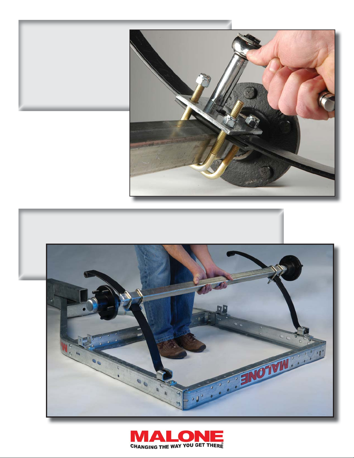
4. Run each nut down but,
ONLY UNTIL THE NUTS
ALMOST TOUCH
THE PLATE !!
You will need lots of wiggle in
the springs to fi t them into the
spring brackets in the next step.
MPG460XT
5. Lift the axle/spring assembly to the trailer frame and slide the slipper spring
ends into the slipper spring brackets as shown. Then lower the axle resting the
spring eyes on the front brackets however they land.
[email protected]
800-295-0042 ext 206
9
Page 10
MPG460XT
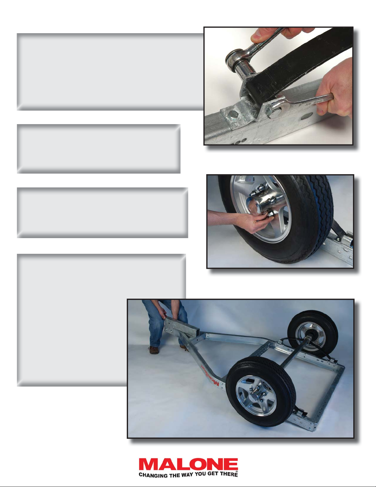
6. Wiggle the spring eyes into the front hanger
brackets and bolt using 1/2” x 3” bolts and self locking nuts. Nuts to the inside. Tighten the shackle
bolts ONLY until they grip the sides of the brackets.
Remember, this is a hinge. The bolt should remain
still in the bracket allowing the spring eye to move
freely.
7. Now that the axle assembly is attached
to the frame, tighten the axle plate U-bolts
evenly until there is a slight bend in the tie
plates. Don’t over tighten.
8. Slip the hub caps thru the wheels from
the back then mount the wheels onto the
hubs. Hand tighten the lug nuts.
9. Grasp the front of the trailer, lift with your
knees and step around the trailer when it
balances on the rear of the frame, then let it
down onto the tires.
ALWAYS BEND FROM YOUR
KNEES WHEN LIFTING.
IF THE TRAILER IS TOO
HEAVY FOR YOU TO LIFT
SAFELY, STOP, GET SOME
FRIENDS TO ASSIST YOU.
10
800-295-0042 ext 206
Page 11
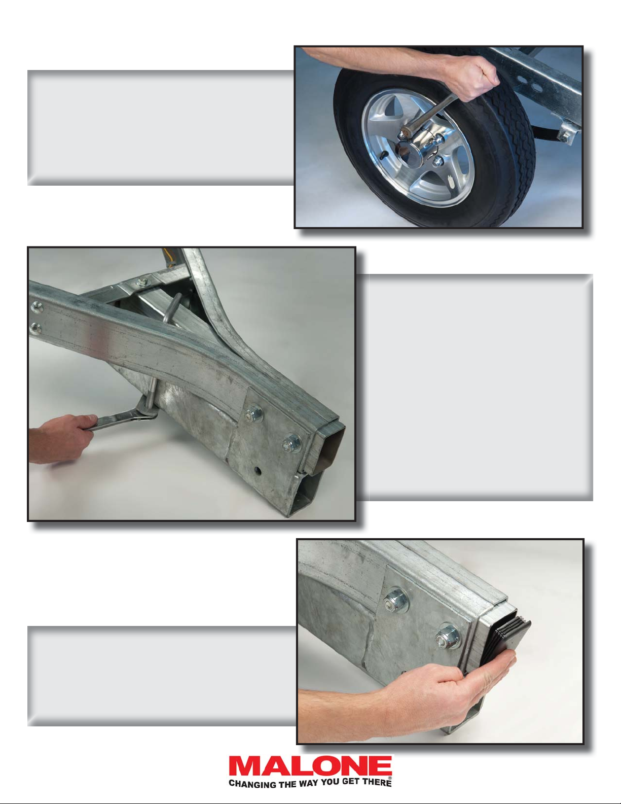
10. Tighten the lug fi rmly to 75 to 85
foot pounds of torque.
MPG460XT
11. Slip the large U-bolt in place
over the retractable tongue assembly
as shown. Install the 2 hole frame
strap under the assembly and install
the 1/2” nuts.
12. Install the 2” x 3” plastic hole plug
into the end of the frame as shown. Use
your hammer to tap it in.
Turn the U-bolt at an angle as shown
so its legs are against the tubes.
Fully tighten the 2 nuts.
Now tighten the bolt in the center of
the rear tongue support.
[email protected]
800-295-0042 ext 206
11
Page 12
MPG460XT
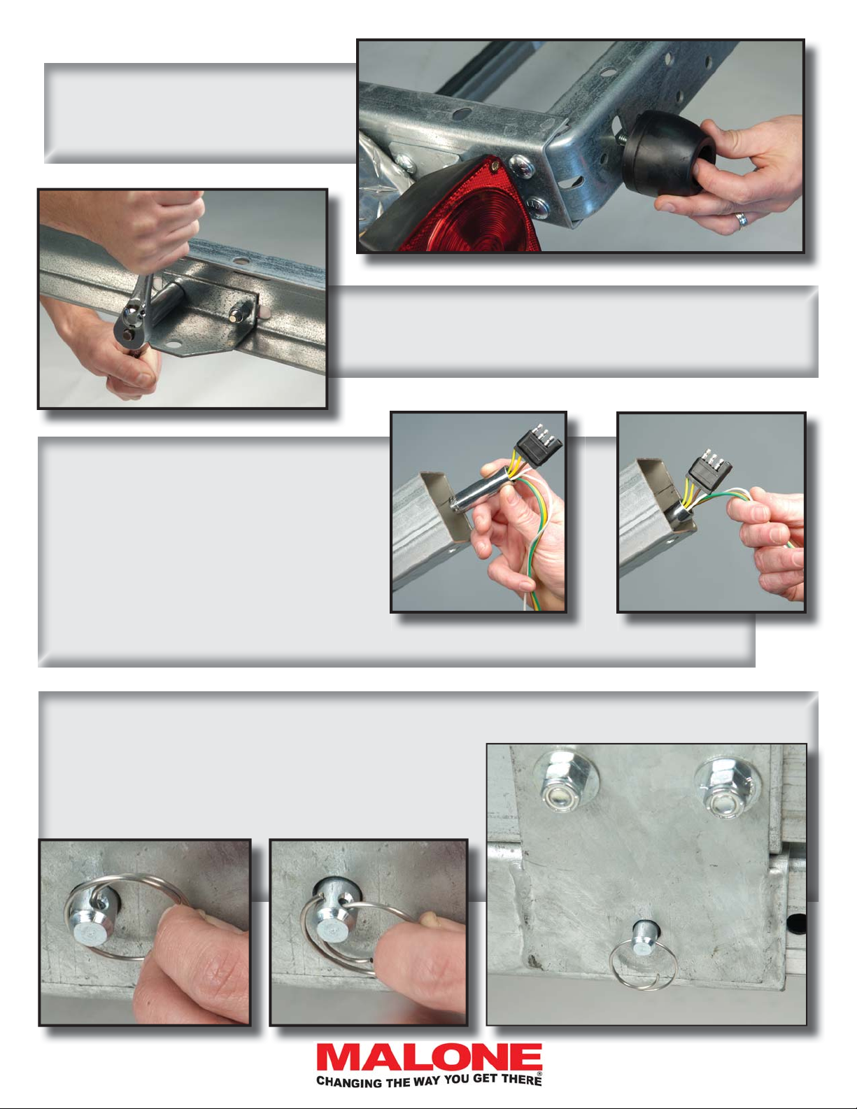
13. Attach the rubber stand-up feet
to the rear of the frame as shown.
14. Attach the retractable tongue retainer bracket to
the inside of the rear frame crossmember as shown.
15. Install the wiring harness extension
thru the tongue. The easiest way is to let
gravity pull the harness through. Make a
fold in the harness near the end with the
white ground wire. Push the fold into a
heavy socket (or tape any heavy object to
the fold). Feed the weight into the tongue
and let gravity pull the harness through.
Remove the weight. Tuck the ends of the harness just inside the tongue.
16. Slide the tongue (end without the white wire) into the retractable receiver box until the hole in
the box aligns with one of the 2 holes in the sides of the
tongue. Pass the hitch pin through and install the ring
clip.
12
800-295-0042 ext 206
Page 13
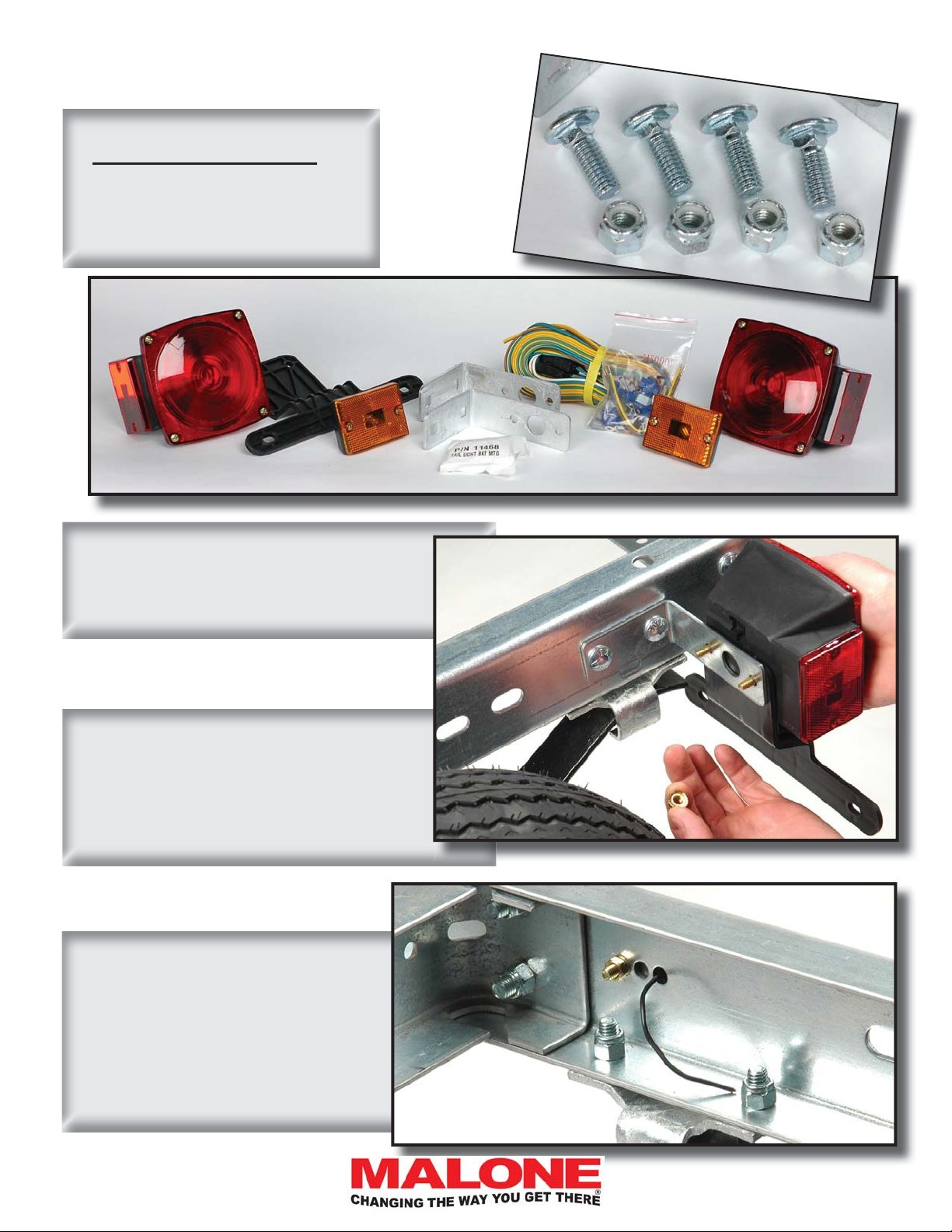
LIGHT ASSEMBLY (Group 3)
REFERENCE:
Trailer Wiring Color Code
•Brown = running lights
•Yellow = left turn / left brake
•Green = right turn / right brake
•White = ground
MPG460XT
1. Attach the tail lamp brackets to
the frame as shown using 3/8” x 1”
carriage head bolts and nuts. No
washers are needed.
2. Sandwich the license plate mounting
bracket between the left side lamp and
the left side tail lamp bracket. Attach
the tail light using the nuts provided with
the lamp kit. Then mount the right side
lamp.
3. Use the 3 holes just above the
spring bracket to mount the amber
side lamps. Put the stud through
the forward hole and the wire
through the rear hole. Tuck the
wire so the lamp sits fl ush on the
frame. The middle hole is unused.
[email protected]
800-295-0042 ext 206
13
Page 14
MPG460XT
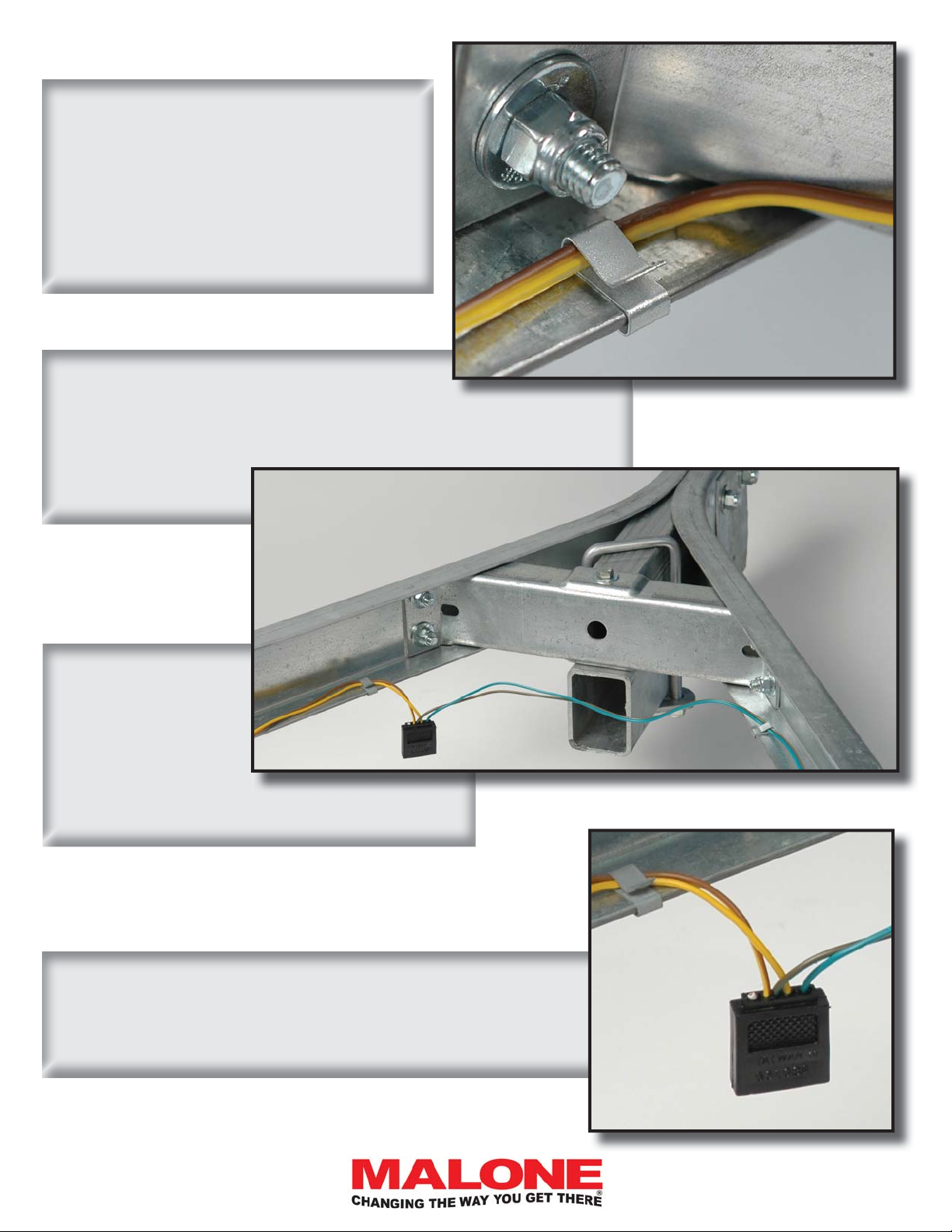
4. Routing the wiring harness.
- Route the GREEN/BROWN wire
along the RIGHT side of the frame.
- Route the YELLOW/BROWN wire
along the LEFT side of the frame.
5. Use the clips provided to secure the wire
to the inside of the frame channel as shown.
6. Position the
harness connector off center close
to a frame rail as
shown. This holds
the connector up at the frame during trailering.
7. The white wire on the connector is not needed at this
location on the trailer. Clip it off fl ush with the connector.
14
800-295-0042 ext 206
Page 15
8. Route the wires thru the
mid cross member as shown
then secure the harness in
place using the frame clips
provided.
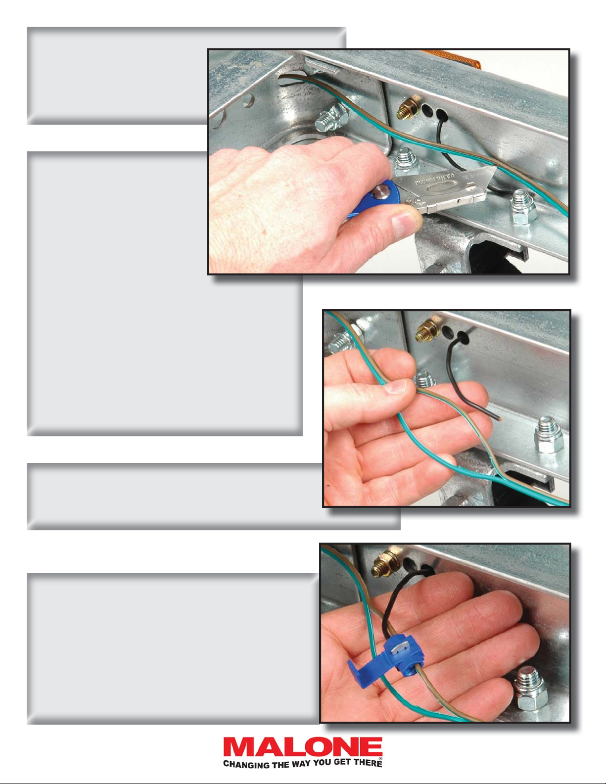
9. Connecting the side
lamps.
To control cutting between
two conductors without damaging the wire or yourself,
press the wire fl at against
the frame then squarely
push the blade tip between
the conductors until it hits the frame. Then
with the knife tip still held fi rmly against the
frame, pull the wire gently away from the
frame so the blade cuts between the wires.
This way you don’t get cut and the risk of cutting too much is greatly reduced.
MPG460XT
Divide only about 1/2” of wire. Set the knife
aside.
10. Grasp either side of the cut with your fi nger-
nails and pull to separate 3” of wire as shown.
11. Press the brown wire into the quick connector as shown. Then insert the wire from the side
marker light fully into the 2nd opening. Use pliers
to squeeze the conductor blade down and thru the
insulation. The blade cuts thru the insulation and
connects the wires inside. Flip the cover to lock
the connector. Repeat on the other side again using the brown wire.
[email protected]
800-295-0042 ext 206
15
Page 16
MPG460XT
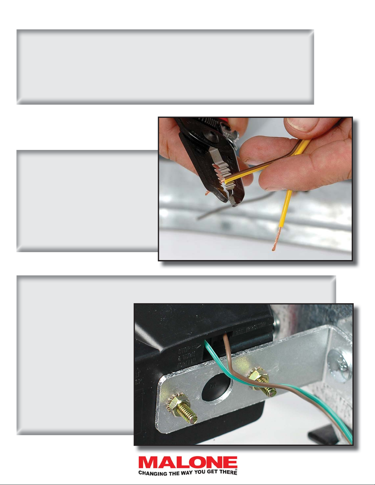
12. Route the wires to the rear along the frame.
- Exit the frame via the slotted hole under the lamp bracket.
- Use wire clips to secure the wires. Bring the wires to the tail lamps, add 10 inches
more to serve as extra length for service work, and cut there. Coil the extra.
13. Strip 1/2” of insulation off the
ends of all 4 tail light wires.
- Slightly twist the exposed copper
strands to stiffen them. Slightly!!
Not too much as the strands of copper are stiffer when more straight
and you will need the stiffness in the
next step.
14. There are holes in the back side of each lamp marked by wire color.
- Identify which hole is for
which color wire. Then
carefully push the twisted
wire straight into the corresponding hole. You will
feel the wire slide under the
wire gripper inside the lamp
as you push the wire into it.
Once the wire is pushed in it
will not come back out. Tug
gently to check for a good
connection. Repeat on the
other side.
16
800-295-0042 ext 206
Page 17
FENDER ASSEMBLY (Group 4)
MPG460XT
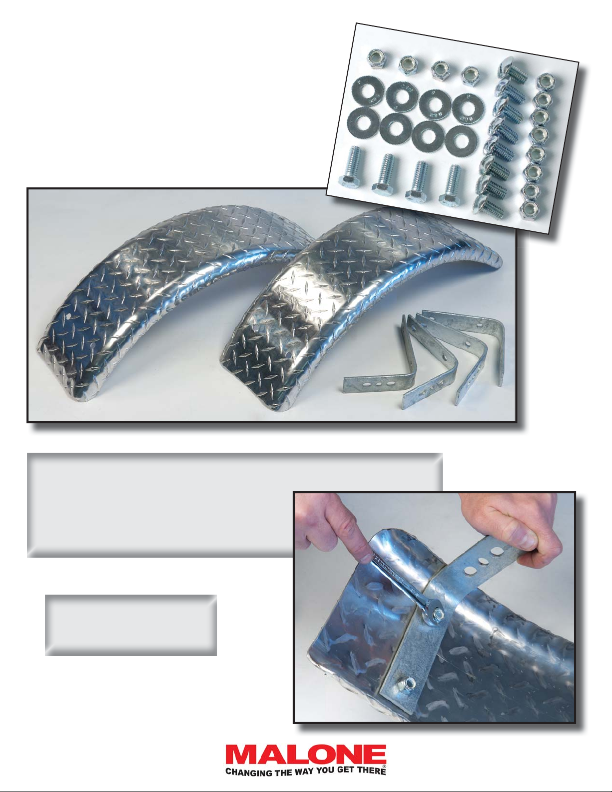
1. Connect all 4 fender brackets to the fenders using 3/8” x 3/4” slot head
screws and nuts. Assemble with the nuts
to the inside of the fenders as shown. No
washers here. Fully tighten all 8 screws
and nuts.
Note: fenders are
symmetrical and fi t on
either side of the trailer.
[email protected]
800-295-0042 ext 206
17
Page 18
MPG460XT
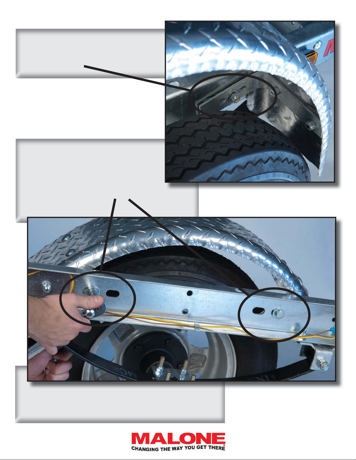
Note that when bolting the mounting brackets to the frame you will install a washer on
both sides, under the head of each bolt and
under each nut.
2. Using 3/8” x 1” bolts, washers on both
sides, and nuts, attach the fender brackets
to the slotted holes in the frame as shown.
NOTE you will use the center hole in the
bracket and the outside two slotted holes in
the frame.
3. Tighten bolts fully and repeat for other side.
18
800-295-0042 ext 206
Page 19
COUPLER ASSEMBLY
(Group 5)
MPG460XT
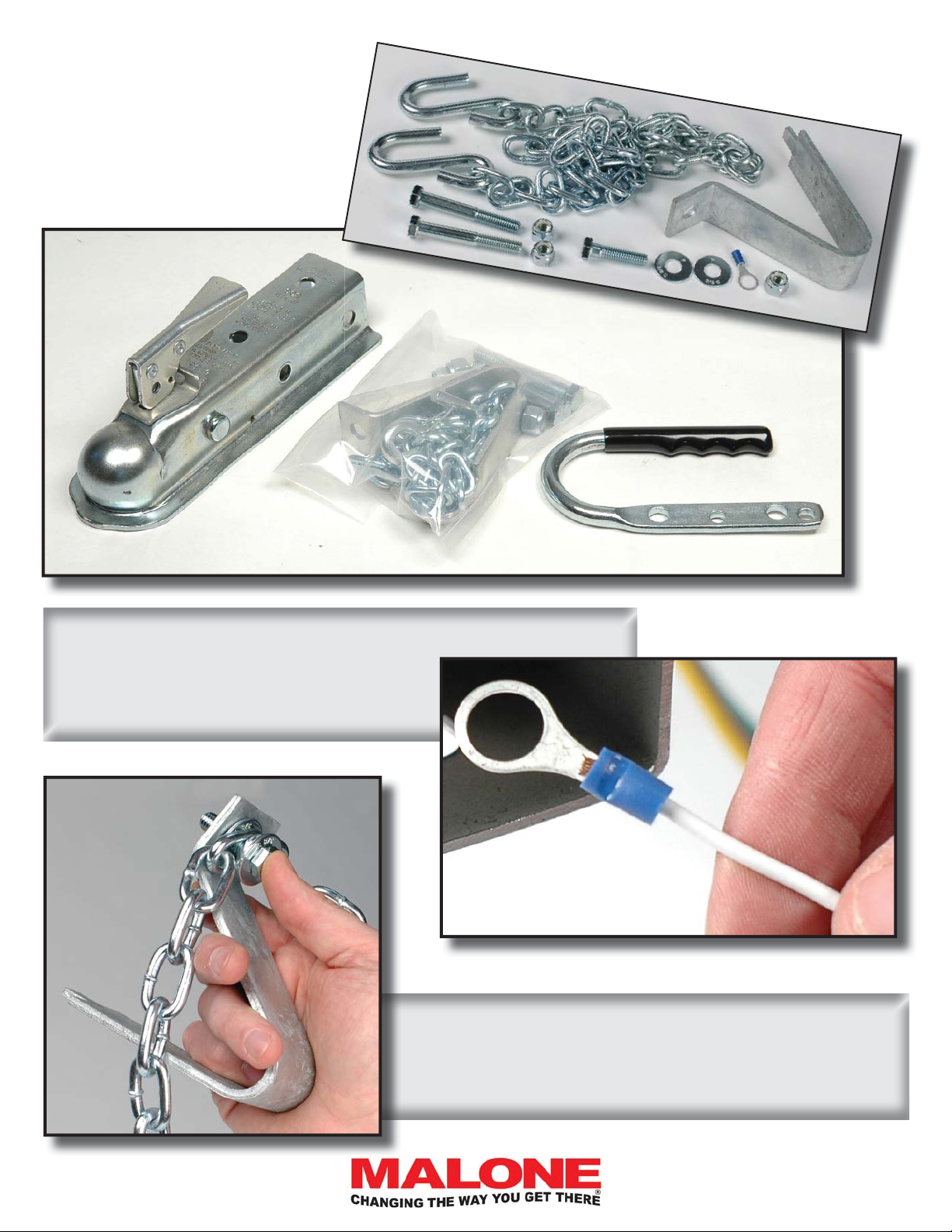
1. Installing the ground wire connector. Strip 3/8” of insulation off the
white ground wire and crimp on the
ring connector as shown.
2. Assemble the tongue skid and safety chain assembly
with a 3/8” x 1-1/2” bolt as shown. Use washers above
and below the chain ends.
[email protected]
800-295-0042 ext 206
19
Page 20
MPG460XT
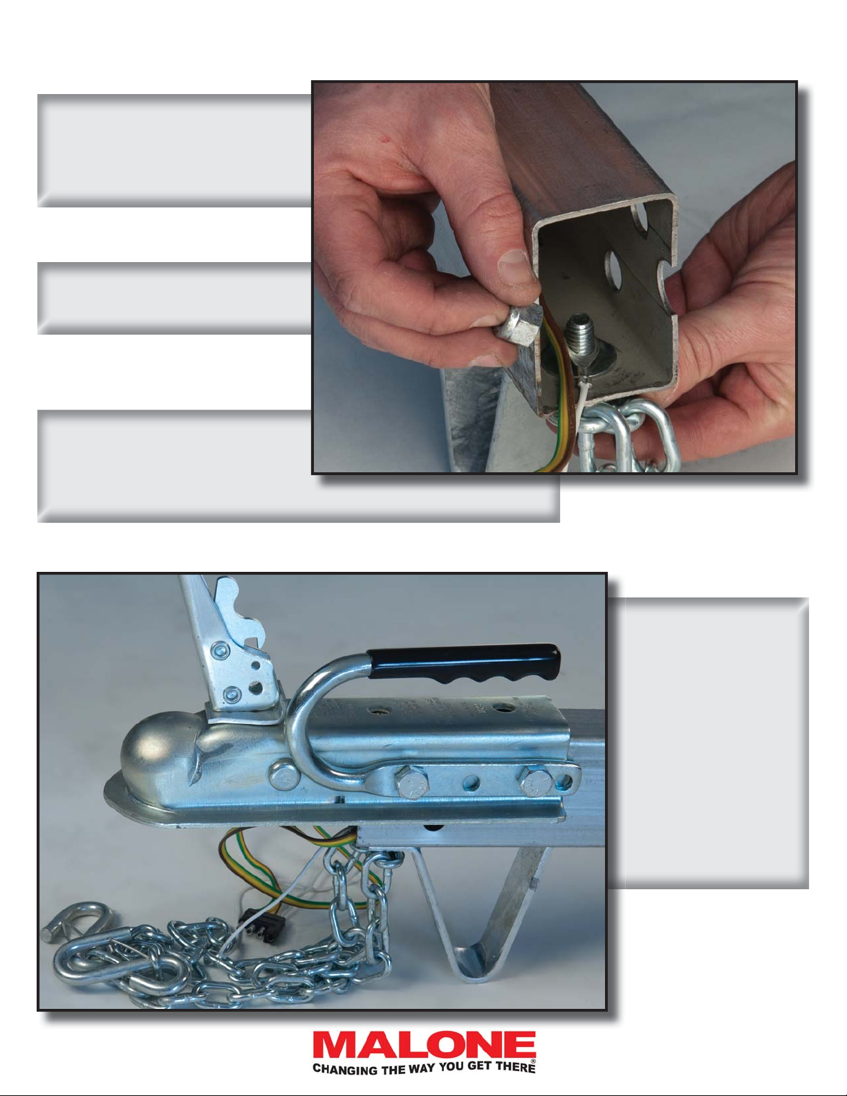
3. Place the skid and chain assembly under the tongue and
insert the bolt up through the
skid bolt hole on the bottom of
the tongue as shown.
4. Slip the ring terminal over
the bolt and install the nylon
lock nut hand tight.
5. Check that the rear end of
the skid is still in its hole in the
bottom of the tongue. Tighten
the bolt while holding the nut
stationary. This way the ring terminal remains straight.
20
6. Install the coupler and coupler
handle onto the
tongue as shown.
Then tighten until
the coupler fi rmly
grips the tongue.
Don’t over tighten
and crush the
tongue.
800-295-0042 ext 206
Page 21
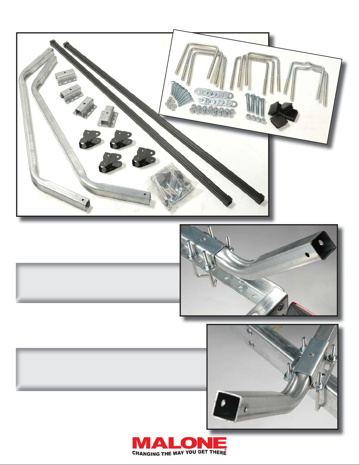
LOAD BAR ASSEMBLY (Group 6)
MPG460XT
1. Attach a load bar support tube onto the rear
cross member. Cross the U-Bolts.
Center the support tube and brackets on the
trailer and tighten.
2. Attach the second support tube 48 inches forward.
Install these U-bolts parallel, not crossed. Measure 48”
on both sides of the trailer to be sure the load bar is on
straight, then tighten the U-bolts.
[email protected]
800-295-0042 ext 206
21
Page 22
MPG460XT
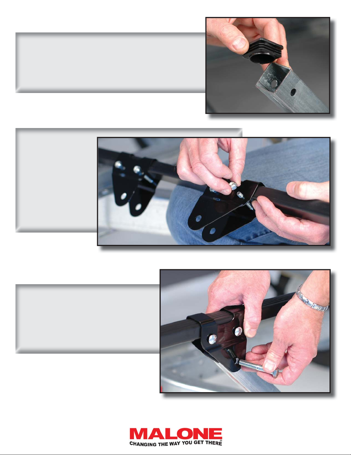
3. Use your hammer and carefully pound the end plugs
into the ends of the support tubes.
4. Slip the load bar
brackets over the
load bars (as shown)
and loosely install the
two small carriage
bolts / nuts through
each bracket trapping
the load bars inside
the brackets.
5. Install and hand tighten the bolts
holding each bracket to the support
tube.
22
800-295-0042 ext 206
Page 23
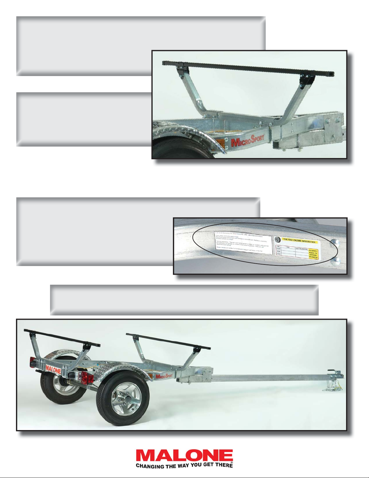
6. Center the load bars to the trailer, then tighten all 12 bracket
bolts.
7. Go back now and re-check that all
nuts and bolts on the entire trailer are
securely tightened.
DECALS, REGISTRATION & TITLING
MPG460XT
Apply the TIRE AND LOADING Decal and the VIN Decal as shown to
the right, onto the left side of the frame.
- Be sure to clean the frame before
applying the decals.
Your MicroSport Trailer is now complete and ready to register and title !
TM
Contact your local DMV offi ce for specifi c procedures in your State.
[email protected]
800-295-0042 ext 206
23
Page 24
MPG460XT
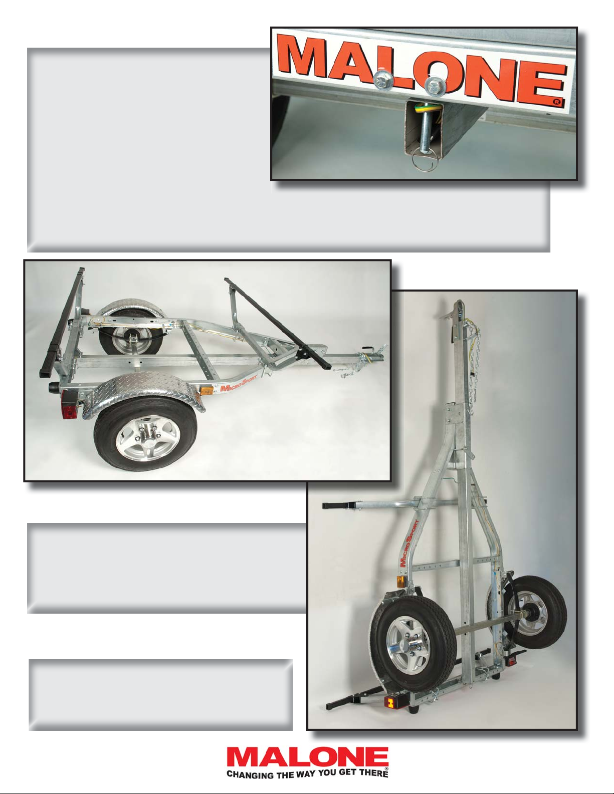
To use the retractable tongue.
1- Disconnect the extension harness from
the frame harness and tuck the harness
into the rear of the tongue.
2- Remove the hitch pin from the frame.
3- Slide the tongue into the frame until the
end of the tongue aligns with the retainer bracket as shown to the right.
4- Install the hitch pin and retainer ring as shown.
When retracted, the trailer may be stood up on
end against a wall, tree or post for reduced footprint storage as shown. When standing, always
secure the trailer so it cannot fall over.
Visit us at maloneautoracks.com
for more fi ne products and accessories.
24
800-295-0042 ext 206
 Loading...