

Malone MegaSport MPG550LB Installation Manual
MALONE
R
MALONE
*ATTENTION CUSTOMERS*
Thank you for your recent purchase of a Malone trailer.
Please inspect all parts and hardware bags prior to assembly.
**Set the large red envelope (in the axle box) containing
important documents in a safe spot.
If you encounter any missing components please contact us at:
Email:technical@maloneautoracks.com
OR
Phone:(207) 774 - 9100 X215
R
Business Hours: Monday-Friday
9am- 5pm
Thank you from all of us at Malone
MPG550LB

MALONE
R
Important Note
Product Warranty & Registration Form
All information is condential and used exclusively by MALONE only.
Dear Customer,
Thank you for your purchase of a Malone Product.
In order to be eligible for the Malone Warranty program, we ask that you contact us by email or
online at one of the following: With-in 30 days of purchase. You can also mail this letter back to the address at
the bottom.
• Online: www.maloneautoracks.com
• Email: Technical@maloneautoracks.com
We will require the information below.
Here is the information collected:
First Name:
Last Name:
Address:
Address2:
City:
State:
Zip:
Country:
Email:
Phone:
Product Description/Name:
Product MPG#
Date Purchased:
Store Where Purchased:
Purchase Price:
Thank you for choosing Malone!
81 County Rd. Ste 1, Westbrook, ME 04092
P: 207.774.9100 F: 207.615.0551
E: sales@maloneautoracks.com W: www.maloneautoracks.com
MPG460XT
Take a few moments and read through these instructions to familiarize yourself
with the step by step assembly process before you begin turning wrenches.
Unpack and sort the components into groups as shown in the following pages.
Then assemble each group in order. Lets get started !!
Required Tools:
• (2) 3/4” wrenches • (2) 9/16” wrenches (a deep socket is recommended)
• Large fl at blade screw driver • (1) 7/16” wrench
• Razor knife • Pliers
• Wire stripping tool • Electrical connector crimping tool
• Lug wrench • Small hammer
Malone MicroSport Trailer
Model MPG460XT Assembly Instructions
TM
REV 2
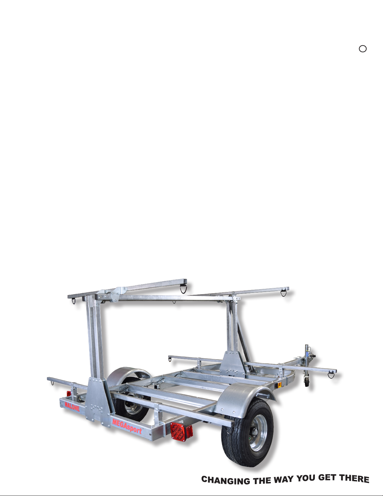
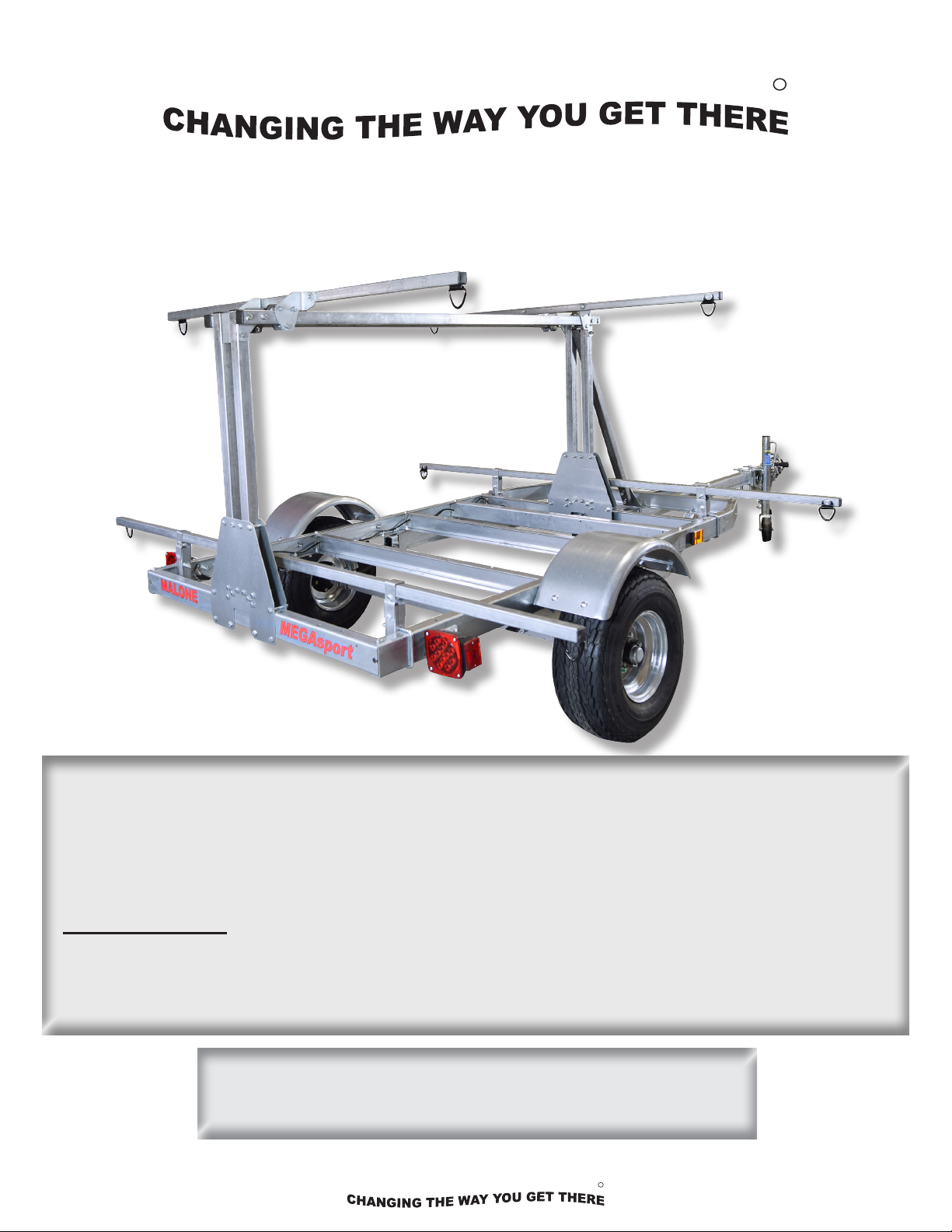
Malone MegaSportTM Trailer
MALONE
MALONE
Model MPG550LB Assembly Instructions
MPG550LB
R
Take a few moments and read through these instructions to familiarize yourself with the
step by step assembly process before you begin turning wrenches.
Unpack and sort the components into groups as shown in the following pages.
Required Tools:
• (2) 3/4” wrenches • (2) 9/16” wrenches (a deep socket is recommended)
• Large at blade screw driver • 7/16” wrench • 3/8” wrench and socket
Then assemble each group in order. Lets get started !!
• Large Phillips head screw driver • Rubber hammer
Visit us at maloneautoracks.com
for more fi ne products and accessories.
technical@maloneautoracks.com
800-295-0042 ext. 215
1
R
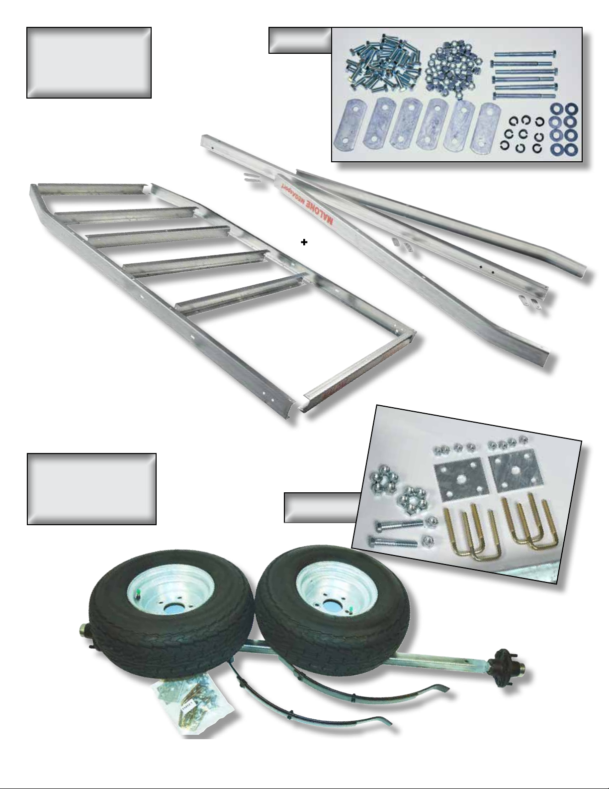
Group 1:
Frame
Components
Main Frame
Bag 11412
+
Group 2:
Axle / Spring
Components
Tongue Frame
Bag 11412-1
Visit www.maloneautoracks.com/Replacement-Parts
for all of your spare part needs
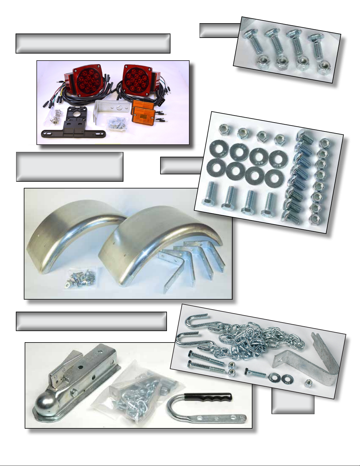
Group 3: Lighting Components
Bag 11468
Group 4:
Fender Components
Group 5: Coupler Components
Bag 11464
Bag 11494
Visit www.maloneautoracks.com/Replacement-Parts
for all of your spare part needs
Bag 11412-2
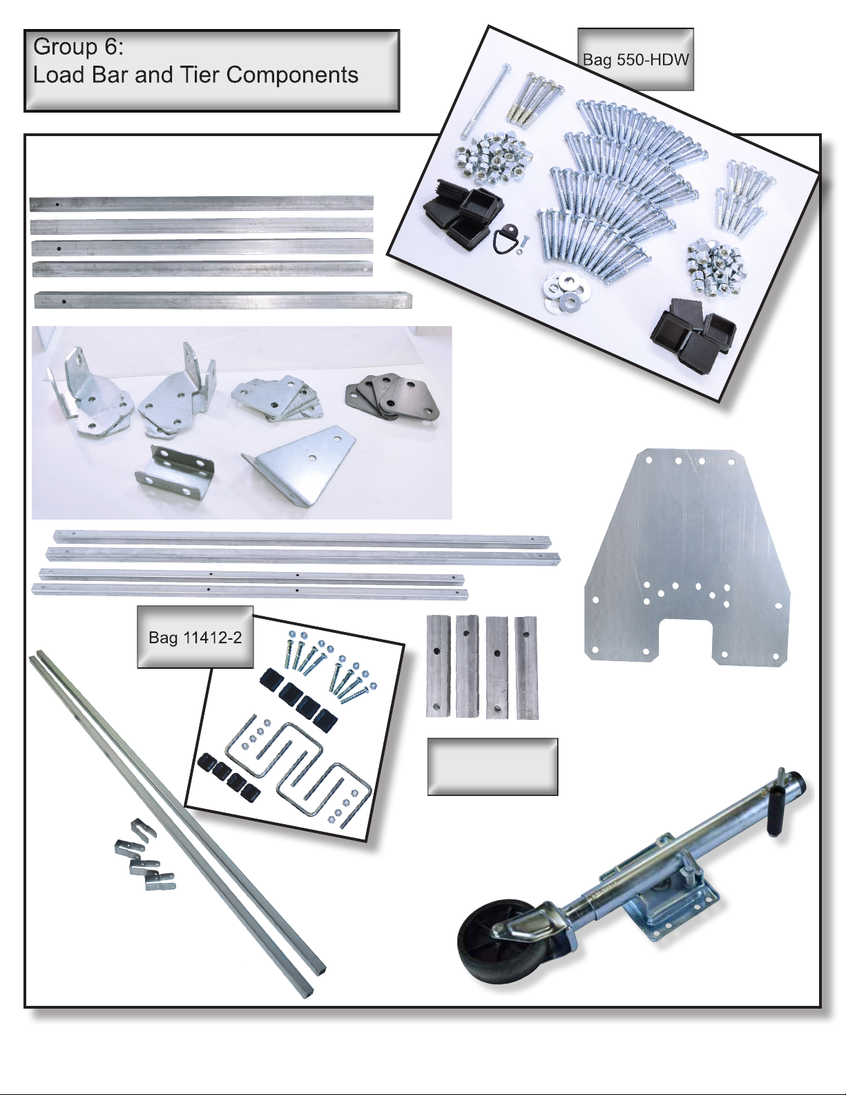
Group 6:
Load Bar
Components
x4
x4
Group 7:
Jack Stand
Visit www.maloneautoracks.com/Replacement-Parts
for all of your spare part needs
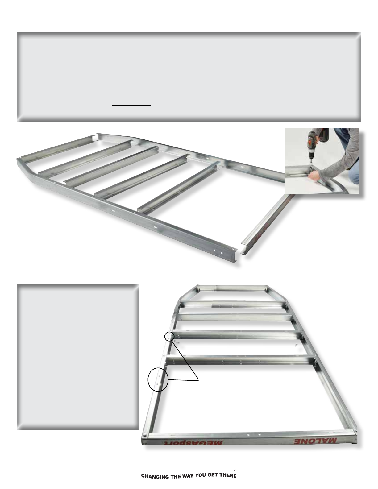
MAIN FRAME ASSEMBLY (Group 1)
MALONE
1. We start the assembly of the Main frame rst, right side up. Aline all the cross members as shown.
NOTE: Direction of 3rd cross member faces forward. Install the bolts downward from the top and secure
with nylon lock nut. Hand Tighten Only.
Measuring from the rear corners diagonally to the front corners will insure your frame is square. Adjust
as needed and fully secure the 4 corners.
We now ip the main frame on its back to make it easier to install the tongue frame, springs and axle.
Once the springs and axle assembly is installed we will ip the trailer over to complete the assembly.
2. With the frame components
upside down as shown install the
remaining hardware for the cross
members, fully tighten the four
corners rst, again measuring to
insure the frame is square.
NOTE: Skip the bolts for the 4th
cross member from the front
until we add the frame rail for
the tongue.
Securing four corners
spring bracket mounting
holes
The spring bracket mounting holes
should be facing up. All the decals
should be upside down.
technical@maloneautoracks.com
5 800-295-0042 ext.215
R
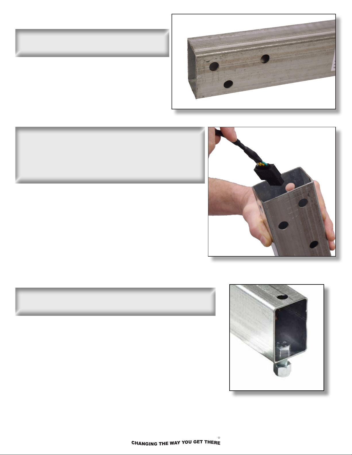
TONGUE ASSEMBLY (GROUP 1)
MALONE
3. Identify the hitch end of the tongue by the 3
holes on the left (drivers) side.
4. Pass the wiring harness (with a plug at each end), into
the open end of the tongue, leaving enough excess at the
front to reach the vehicle. NOTE: MAKE SURE YOUR
PLUG MATCHES THE VEHICLE CONNECTION. IF NOT
REVERSE YOUR WIRING HARNESS NOW.
5. Add the tongue safety bolt at the non-coupler end as pictured.
NOTE: Wires removed for clarity
technical@maloneautoracks.com
6 800-295-0042 ext.215
R
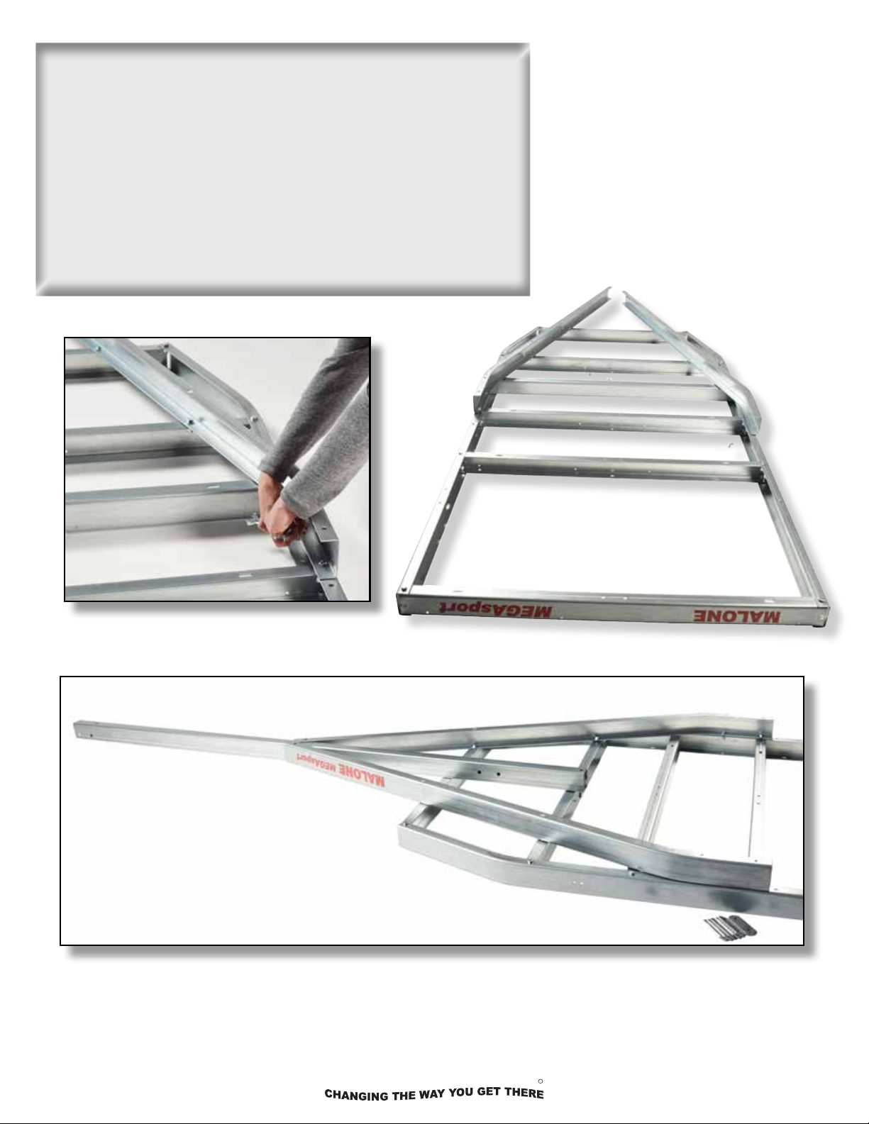
6. Begin attaching the tongue components with the side frame
MALONE
rails rst, then the tongue down the middle.
8. Begin attaching the tongue components with the side frame
Tighten the side rails beginning at the 4th cross member
rails rst, then the tongue down the middle.
back, going through both the main frame rail and the cross
member, joining them together. Working your way forwards,
Tighten the side rails beginning at the 4th cross member back,
the side rails will pinch together at the tongue. You’ll use
going through both the main frame rail and cross member,
washers on the front 2 cross members utilizing the larger oval
joining them together. Working your way forwards, the side
holes.
rails will pinch together at the tongue. You’ll use washers on
front 2 cross members utilizing the larger oval holes.
technical@maloneautoracks.com
7 800-295-0042 ext.215
R
7.
MALONE
9. Secure the tongue to the main frame and frame rails with
the at plates and longer bolts. Placing one plate on each
side of the tongue as pictured.
8.
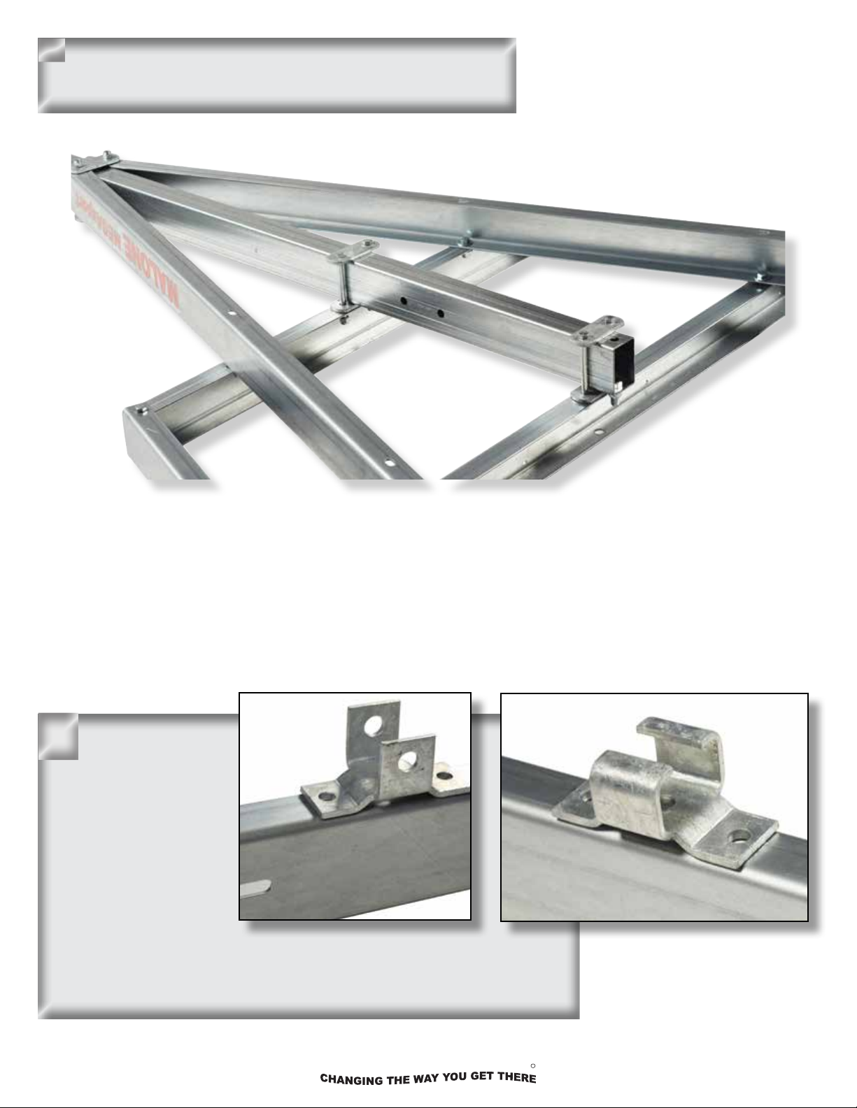
10. Attach the spring
hanger brackets to the
frame. Right at the end
of tongues side rail.
The U shaped shackle
bolt brackets mount
to the front and the C
shaped “slipper” brackets mount to the rear
as shown. Use 3/8” x
1” bolts and nuts. Assemble with the nuts on the inside of the frame
rails. Fully tighten all 8 bolts now.
technical@maloneautoracks.com
8 800-295-0042 ext.215
R

SPRING AND AXLE ASSEMBLY
MALONE
(Group 2)
1. Set the envelope containing the manufacturer’s
certicate of origin (MCO) and VIN labels aside in a
safe place.
*Set the large red envelope
(in the axle box) containing
important documents in a safe spot.
2. Spin the axle to nd the side with the spring
centering holes. These holes mate with the spring
center stud (shown to the left)
technical@maloneautoracks.com
9 800-295-0042 ext.215
R

4. Run each nut down UNTIL IT
MALONE
TOUCHES THE PLATE ONLY!
DON’T TIGHTEN !!
You will need to wiggle the
springs to t them into the
spring brackets in the next step.
5. Lift the axle/spring assembly to the trailer frame and slide the slipper spring
ends into the slipper spring brackets as shown.
technical@maloneautoracks.com
10 800-295-0042 ext.215
R
 Loading...