

Page 1
Serial Number:
Purchased from:
Date Installed:
Installed by:
Head Office and Customer Service
Email: [email protected]
ABN 95 001 717 791
9-11 McKay Avenue
PO Box 373
Leeton NSW 2705
Phone: +61 2 6953 7677
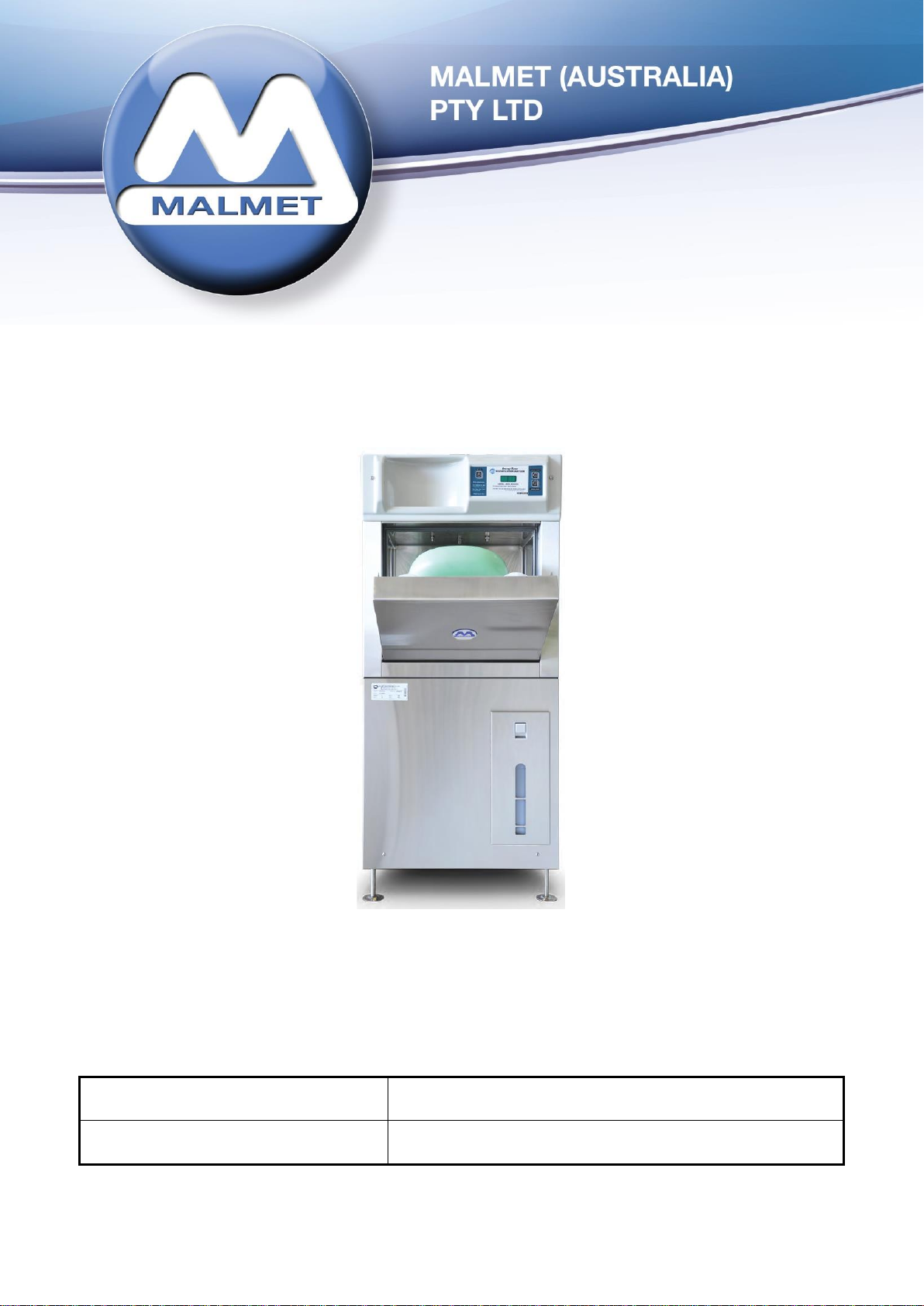
Bedpan / Urinal Bottle Washer
Disinfector
Models ES915, ES935
Detergent Models with Hands Free Operation
Operation, Maintenance and
Installation Manual
Note: Due to Malmet’s policy of continuous product improvement;
design and technical specifications are subject to change without notice.
It is important that the name from whom you purchased your device and the name of the installer are recorded above. The installer is
responsible for the correct installation, start up and demonstrating the operation of this device. They are also responsible for issuing relevant
certificates of compliance (these may differ from state to state).
Issue 3
Page 2

Malmet Bedpan / Urinal Bottle Washer Disinfector (ES-D)
Detergent Model with Hands Free Operation
Operation, Maintenance and Installation Manual
Table of Contents
Foreword .............................................................................................................................................. 3
Quality Policy........................................................................................................................................ 3
Certifications ........................................................................................................................................ 3
Important Warranty Reminder ............................................................................................................ 3
Malmet Head Office and Factory Contact Details ............................................................................... 3
Safety Instructions - Warnings ............................................................................................................. 4
Design Parameters ............................................................................................................................... 5
Section A – Device Operation ............................................................................................................... 6
Hands Free Operation .......................................................................................................................... 6
Detergent ............................................................................................................................................. 7
Changing the Detergent Bottle ............................................................................................................ 8
Disposal of Empty Detergent Bottles ................................................................................................... 8
Loading Configurations ........................................................................................................................ 9
Cycle of Operation .............................................................................................................................. 11
Sequence of Operation ....................................................................................................................... 12
Display Board ..................................................................................................................................... 17
Section B – Device Maintenance ........................................................................................................ 18
Preventative Maintenance Schedule ................................................................................................. 18
Safety Checks ..................................................................................................................................... 20
Replacement of Safety Devices .......................................................................................................... 20
Fault Finding Guide ............................................................................................................................ 21
Appendix A – Faults ............................................................................................................................ 22
Appendix B – Additional Faults not detected by micro-processor ..................................................... 25
Electrical Diagram – 20 Amp Models (ES915) .................................................................................... 26
Electrical Diagram –10 Amp Models (ES935) .................................................................................... 27
Hydraulic Circuit Diagram ES915/935 ................................................................................................ 28
Section C – Device Installation ........................................................................................................... 29
Service Connections............................................................................................................................ 30
Dimensions and Service Entry Points ................................................................................................. 31
Electrical ............................................................................................................................................. 32
Post Installation Precautions ............................................................................................................. 33
Positioning of Bedpan Washer Disinfector ........................................................................................ 34
Installation and Service Connection Layout Details ........................................................................... 36
Plumbing ............................................................................................................................................ 37
Technical Specifications ..................................................................................................................... 37
Device Specifications .................................................................................................................... 38/39
Warranty Statement .......................................................................................................................... 39
Quick Reference Guide ....................................................................................................................... 43
Issue 3 Page 2 04/10/2019
Page 3

Malmet Bedpan / Urinal Bottle Washer Disinfector (ES-D)
Detergent Model with Hands Free Operation
Operation, Maintenance and Installation Manual
Foreword
To obtain maximum life and efficiency from your Malmet Bedpan / Urinal Bottle Washer Disinfector and to
ensure safe operation, please read this manual thoroughly and follow all instructions before operating the
device.
This manual provides information on the operation of the device. It is recommended that all persons
operating the device have access to this manual for training purposes.
This unit is not intended for use by any person without the proper training, experience or knowledge.
The specifications supplied in this manual were in effect at the time of publication. However, owing to
Malmet (Australia)’s policy of continuous improvement, changes to these specifications may be made at
any time without notice on the part of Malmet (Australia).
Quality Policy
Malmet’s quality management system is certified to ISO 9001:2015 and ISO 13485:2016 and guarantees
the quality of this product.
Certifications
Electrical Safety: Cert No. CS10847N to IEC 61010-2-040, IEC 61010-1
EMC Compliance: Report T130119 to IEC 60601-1-2
Watermark: Cert No. WMKA21156
Important Warranty Reminder
Should you have any problems with your device, contact the company from whom you purchased it, or
Malmet (Australia) Pty Ltd.
It is important that the name from whom you purchased your device and the name of the installer are
recorded on the front page of this manual. The installer is responsible for the correct installation, start up
and demonstrating the operation of this device. They are also responsible for issuing relevant certificates
of compliance (these may differ from state to state).
Malmet Head Office and Factory Contact Details
Malmet (Australia) Pty Ltd
9-11 McKay Avenue
PO Box 373
LEETON NSW 2705
Telephone: +61 2 6953 7677
E-mail: [email protected]
Website: www.malmet.com.au
Issue 3 Page 3 04/10/2019
Page 4
Malmet Bedpan / Urinal Bottle Washer Disinfector (ES-D)
Detergent Model with Hands Free Operation
Operation, Maintenance and Installation Manual
Safety Instructions - Warnings
Please read and understand this manual before using this device, if this device is used in a manner not
specified by the manufacturer protection by the device may be impaired.
Please refer to this manual for information wherever this warning symbol is displayed -
Be aware of 240V Voltage
Disconnect power when servicing
Mains power ISO switch or circuit-breaker must be in an
accessible position, easily reached and not obstructed so device
can be isolated from mains power during service
Only process items listed as per the design parameters in this
manual
Be aware of steam discharge
Goods and racks are hot to handle
Safety gloves and goggles must be worn when changing detergent
Safety clothing with reflective tape can activate the hands free
sensor when device is in standby mode
Be aware of hot surface, pipes and hoses from steam and hot
water
Install temperature probes and element over temperature
protection thermal cut-outs correctly
Plumbing service connection must comply with AS/NZS 3500
Issue 3 Page 4 04/10/2019
Page 5

Malmet Bedpan / Urinal Bottle Washer Disinfector (ES-D)
Detergent Model with Hands Free Operation
Operation, Maintenance and Installation Manual
Design Parameters
The Malmet Bedpan / Urinal Bottle Washer Disinfector has been designed within the following parameters:
a) A single bedpan with lid and two urinal bottles can be emptied, cleaned and disinfected during each
automatic cycle.
The utensils that can be cleaned in the device are:-
i) Standard size bed pans
ii) Standard commode bowl
iii) Standard male and female urinal bottles
iv) Most plastic urinal bottles including male non-spill and female cervec
v) Small slipper pan
vi) Large slipper pan
b) The cradle is designed to ensure that utensils are not dislodged during the cleaning cycle; the contents
are emptied during door closure.
c) The chamber and door are self-cleaning and do not permit water or soil to remain after a properly
completed cycle. Steam disinfection ensures all internal surfaces are totally clean and safe.
d) The flush and clean stage:
i) Removes the soil
ii) Clears the trap
e) A complete cycle is completed in approximately four (4) minutes for the 20 Amp Bedpan /Urinal Bottle
Washer Disinfector and six (6) minutes and thirty (30) seconds for the 10 Amp Bedpan / Urinal Bottle
Washer Disinfector
Note: Dependant on ambient air temperature.
Note: The first cycle will take longer as the device has to reach the operating water temperature of
90˚C.
f) Malmet Door Obstruction Feature
This is factory set to 12Nm ±10%; causing the door to re-open when an obstruction is detected. This is
designed to protect the integrity of the device and the articles within.
Disconnect power when servicing
Issue 3 Page 5 04/10/2019
Page 6
Malmet Bedpan / Urinal Bottle Washer Disinfector (ES-D)
Detergent Model with Hands Free Operation
Operation, Maintenance and Installation Manual
Section A – Device Operation
For the safe use of this device the responsible body should ensure that all operators are adequately trained
to operate and maintain the device in its safe use.
Hands Free Operation
Zero Contamination – Totally Hands Free
The Malmet Bedpan / Urinal Bottle Washer Disinfector is fully automatic.
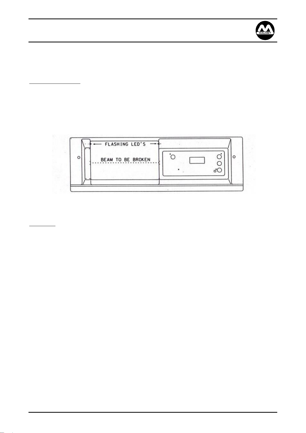
Door open, door close and cycle start can be activated without touching the device.
Front View
Manual operation of the door and a manual start button are available.
To Operate
To Open Door – Break Sensor Beam
To Close Door – Break Sensor Beam
To Start Cycle – Break Sensor Beam once when green LED’s flash within 8 seconds after door
closure
Note: If door is opened then closed and cycle has not commenced the beam must be broken twice.
Issue 3 Page 6 04/10/2019
Page 7
Malmet Bedpan / Urinal Bottle Washer Disinfector (ES-D)
Detergent Model with Hands Free Operation
Operation, Maintenance and Installation Manual
Detergent
The detergent system delivers 30ml of concentrated detergent in the initial wash stage.
Current Safety Data Sheet for Malmet Device Detergent is available in pdf format from Malmet’s website.
www.malmet.com.au
Detergent Out Condition - F 30 Fault
If insufficient detergent is available to deliver the required quantity, the device will display an F 30 dEt fault.
Access to the load will be restricted until the condition is rectified.
To rectify this fault, install a new detergent bottle as per the procedure in this manual “Changing the
Detergent Bottle”.
On completion of changing the detergent bottle, press either the “Manual Door” or “Manual Start” button
to initiate a priming sequence. If priming is successfully the fault will clear and door will open. Inspect the
items, ensuring they have been cleaned sufficiently before unloading. It is recommended the items are
reprocessed in the event of an F 30 dEt Fault.
If priming is unsuccessful, access to the load will continue to be restricted and F 30 dEt fault displayed.
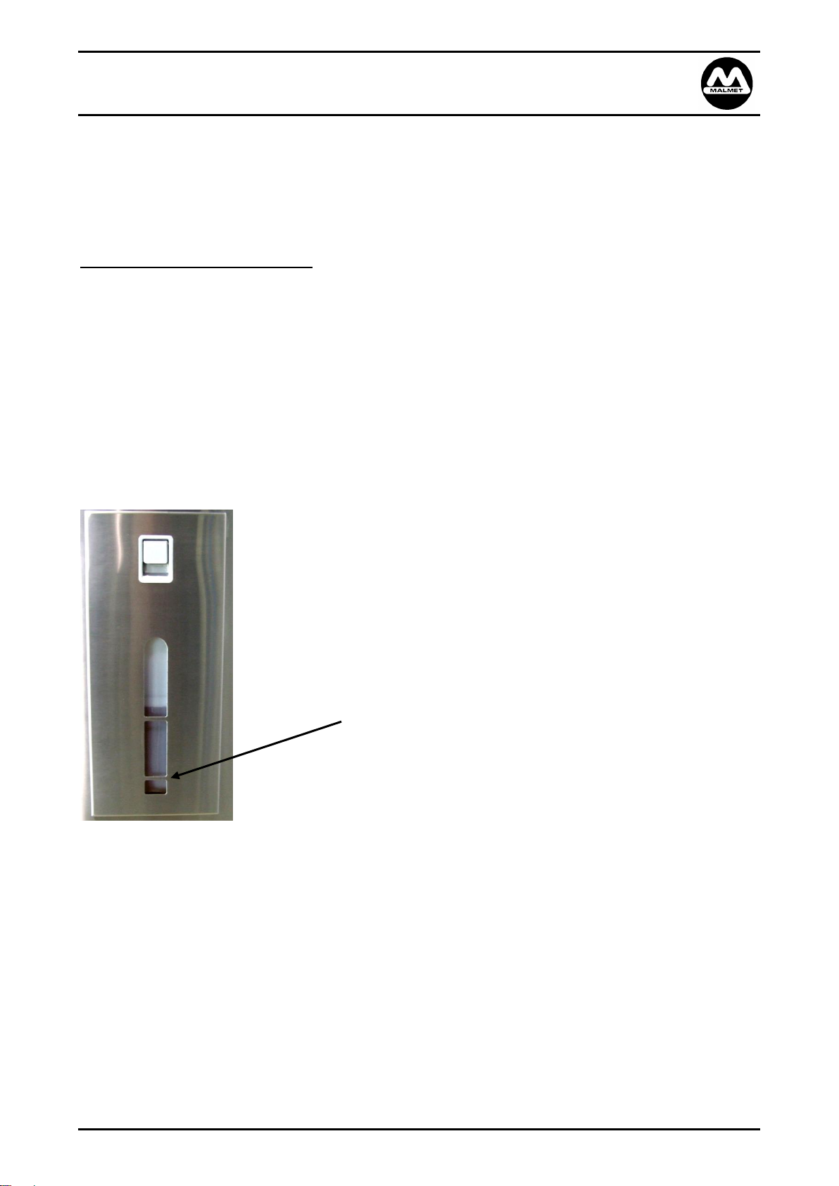
To avoid the detergent out condition check the low level
mark on detergent door, replace detergent when the
detergent level reaches this mark.
Issue 3 Page 7 04/10/2019
Page 8
Malmet Bedpan / Urinal Bottle Washer Disinfector (ES-D)
Detergent Model with Hands Free Operation
Operation, Maintenance and Installation Manual
WARNING!
SAFETY GLOVES AND GOGGLES MUST BE WORN WHEN
CHANGING DETERGENT AND DISPOSING OF EMPTY CONTAINERS
Current Safety Data Sheet for Malmet Device Detergent is available in pdf format from Malmet’s
website. www.malmet.com.au
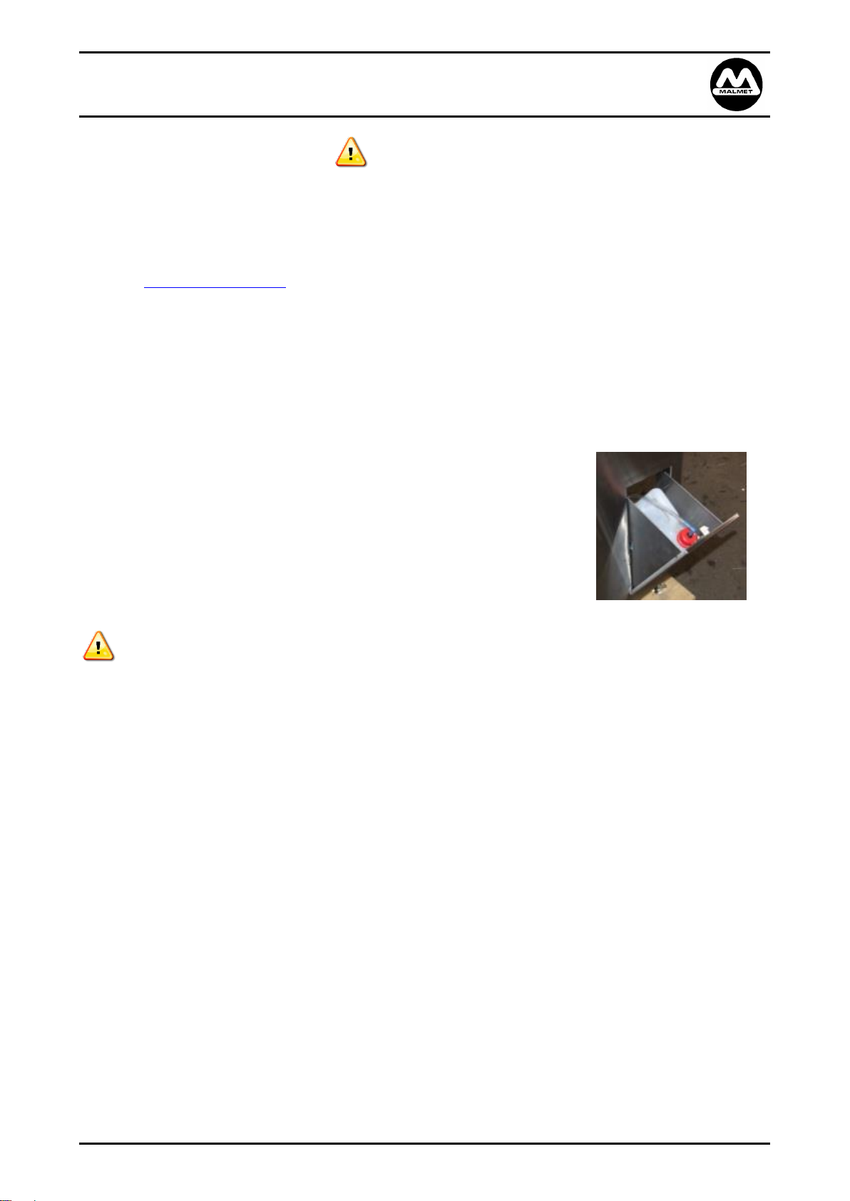
Changing the Detergent Bottle
1. Pull latch on detergent door and open.
2. Unscrew cap and pull out with suction hose (let hose hang in detergent chamber).
3. Remove empty bottle and replace with full bottle.
Note: Leave cap on new bottle until in position.
4. Remove cap on new bottle and fit existing hose and cap.
5. Close detergent door.
6. Restart device operation as normal.
Disposal of Empty Detergent Bottles
1. When handling empty containers treat as though container is full and wear appropriate PPE as per
MSD requirements.
2. Triple rinse container and puncture base to render unusable.
3. Dispose of containers as per facility chemical waste handling procedures, and/or local government
requirements.
Issue 3 Page 8 04/10/2019
Page 9
Malmet Bedpan / Urinal Bottle Washer Disinfector (ES-D)
Push down slipper pan
until it locks into
position
Detergent Model with Hands Free Operation
Operation, Maintenance and Installation Manual
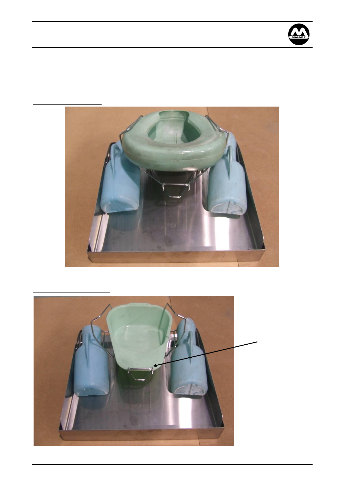
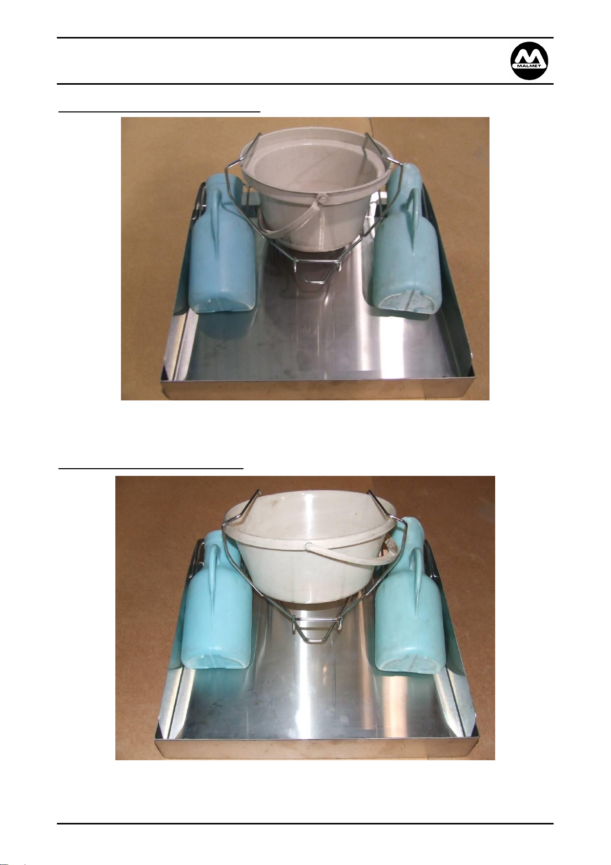
Loading Configurations
The device is intended to be loaded as per the below configurations, please refer to the design parameters
section of this manual for items that this device is designed to process. Part loads or singular items can be
processed but must be loaded in their designated positions as below.
Bed Pan + 2 Urinal Bottles
Slipper Pan + 2 Urinal Bottles
Issue 3 Page 9 04/10/2019
Page 10
Malmet Bedpan / Urinal Bottle Washer Disinfector (ES-D)
Detergent Model with Hands Free Operation
Operation, Maintenance and Installation Manual
Standard Commode Bowl + 2 Urinal Bottles
Large Commode Bowl + 2 Urinal Bottles
Issue 3 Page 10 04/10/2019
Page 11

Malmet Bedpan / Urinal Bottle Washer Disinfector (ES-D)
Detergent Model with Hands Free Operation
Operation, Maintenance and Installation Manual
Cycle of Operation
Stage 1 Flushing / Cleaning
One rotating 180° back spray
Two fixed 60° top sprays
Two fixed urinal sprays
Rinse for 10 seconds
Detergent pump on for 7 seconds to add 30ml of concentrate to pump
Main pump on for 3 seconds to apply detergent
Pause for 40 seconds
Rinse for 10 seconds to wash detergent off
Stage 2 Thermal Disinfection
Steam is delivered into the sealed wash chamber
Steam continues to heat the surface temperature of utensils and chamber to a minimum of 90°C
for 60 seconds
Stage 3 Cool Down Rinse
One 60° fine mist top spray delivers cold water direct from mains.
Utensils are cooled to 55°C for safe handling.
In accordance and complies with:
Cleaning Efficacy
AS/NZS 4187:2014, ISO 15883-1, ISO/TS 15883-5
Thermal Disinfection
AS/NZS 4187:2014, ISO 15883-1
Issue 3 Page 11 04/10/2019
Page 12
Malmet Bedpan / Urinal Bottle Washer Disinfector (ES-D)
Detergent Model with Hands Free Operation
Operation, Maintenance and Installation Manual
Sequence of Operation
1. Once device is installed into position with power and water connected, push power on button.
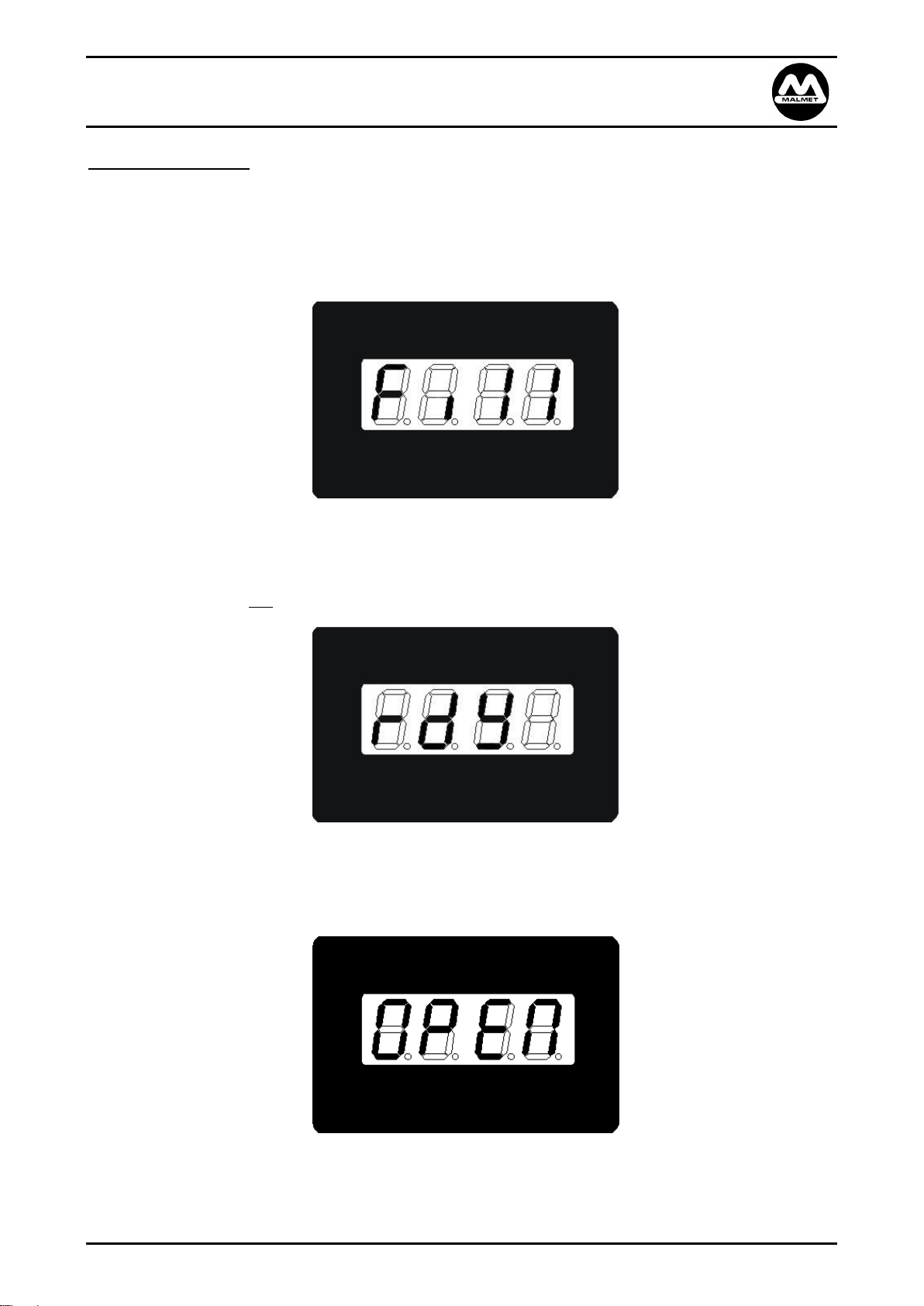
2. When the device is turned on via the display panel the display shows fill indicating steam generator
and cold water tanks are filling to the high water level.
At this stage the device will not commence a cycle until Step 5.
3. Once the steam tank water level probes sense the tank is full it will start heating.
4. The steam tank is heated to temperature 90°C - 92°C. The device is now ready to commence a cycle.
The display shows rdY (ready).
5. The operator breaks the infra-red beam, which opens the door.
The display shows open.
Note: Whenever the door is opened the elements are in the off mode.
Issue 3 Page 12 04/10/2019
Page 13
Malmet Bedpan / Urinal Bottle Washer Disinfector (ES-D)
Detergent Model with Hands Free Operation
Operation, Maintenance and Installation Manual
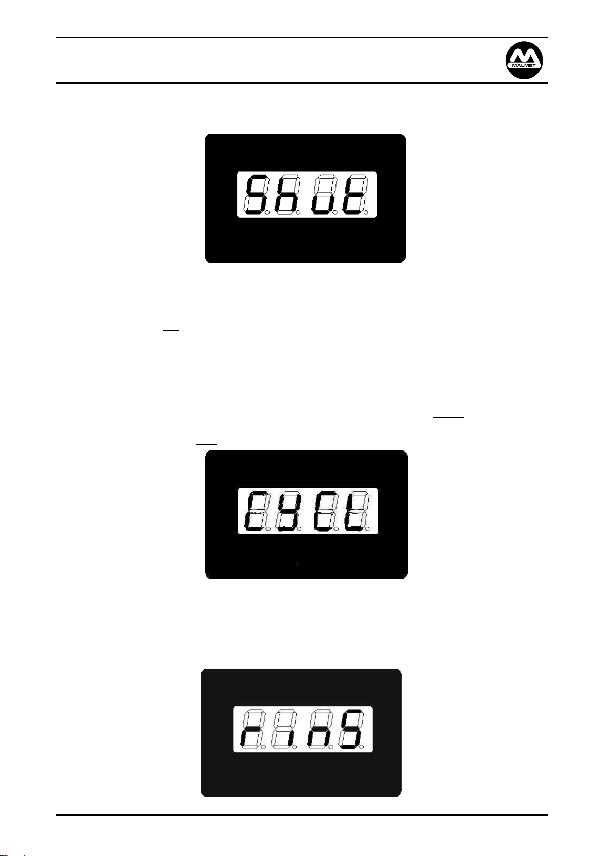
6. Once the device is “loaded” the operator breaks the infra-red beam to close the door.
The display shows Shut
7. When the door is fully closed 2 green LED’s will flash in the infra-red sensor area for 8 seconds to advise
the user to break the beam again to start a cycle.
The display shows rdY
If the 8 seconds has elapsed the flashing LED’s will stop and the device will not start for a cycle. The
operator has to repeat the process from Step 5 (or press manual start).
Note: If this occurs the beam must be broken twice.
Note: On 10A models, if the steam generator temperature is not at 90°C after the beam has been
broken or the manual start button pressed, the display will show “CYCL”. The Green LED’s
will stop flashing and stay on. When the steam generator has reached temperature the
display will show rinS and the wash cycle will start automatically.
8. Once a cycle has been initiated the elements are turned on in the steam tank to start heating the
water.
The wash pump is turned on for 10 seconds for the initial wash.
The display shows rinS
Issue 3 Page 13 04/10/2019
Page 14
Malmet Bedpan / Urinal Bottle Washer Disinfector (ES-D)
Detergent Model with Hands Free Operation
Operation, Maintenance and Installation Manual
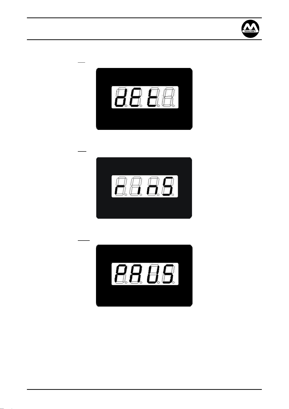
9. Detergent pump comes on delivering 30ml of concentrate to rinse pump.
The display shows dEt
10. Rinse pump comes on to distribute detergent over and inside items
The display shows rinS
11. Pause for 40 seconds so detergent can take effect
The display shows PAUS
Issue 3 Page 14 04/10/2019
Page 15

Malmet Bedpan / Urinal Bottle Washer Disinfector (ES-D)
ACTUAL
CHAMBER TEMP.
Detergent Model with Hands Free Operation
Operation, Maintenance and Installation Manual
12. Rinse pump comes on for 10 seconds to rinse detergent from items
The display shows rinS
13. Once the wash cycle is complete the display will begin to flash the internal chamber temperature
during heating until the disinfection temperature is reached. At this point the fill solenoid is disabled
and will not operate until Step 19.
14. The elements in the steam generator heat to produce steam, which is directed into the wash chamber
raising the internal cabinet temperature above 90°C.
15. Once the internal cabinet temperature has reached 90°C the temperature display will stop flashing and
the disinfection cycle will commence.
16. All elements on 20 Amp models and 10 Amp models will continue to heat during the disinfection cycle
until the internal cabinet temperature reaches 91°C.
Issue 3 Page 15 04/10/2019
Page 16
Malmet Bedpan / Urinal Bottle Washer Disinfector (ES-D)
Detergent Model with Hands Free Operation
Operation, Maintenance and Installation Manual
17. For 20 Amp models, at 91°C one element will turn off and at 92°C another element will turn off. For 10
Amp models, at 91°C one element will turn off. For all models, one element will remain on until 15
seconds before the end of the cycle. If the internal cabinet temperature falls below 92°C, the second
element will turn back on and if the cabinet temperature falls below 91°C, the third element will turn
back on.
Note: Regardless of element combinations 15 seconds before the end of the cycle ALL elements will
turn off. This is to overcome the effects of overshoot in the steam generator producing
steam at the end of the disinfection cycle.
18. The maximum time allowable for the disinfection cycle is 10 minutes. If this time is exceeded then the
device will go to fault and elements turn off.
19. After the disinfection cycle is complete the cooling solenoid will turn on for 15 seconds. This will cool
down the surface temperature of the utensils and make them safe to handle.
The display shows cool. This water is direct from the mains.
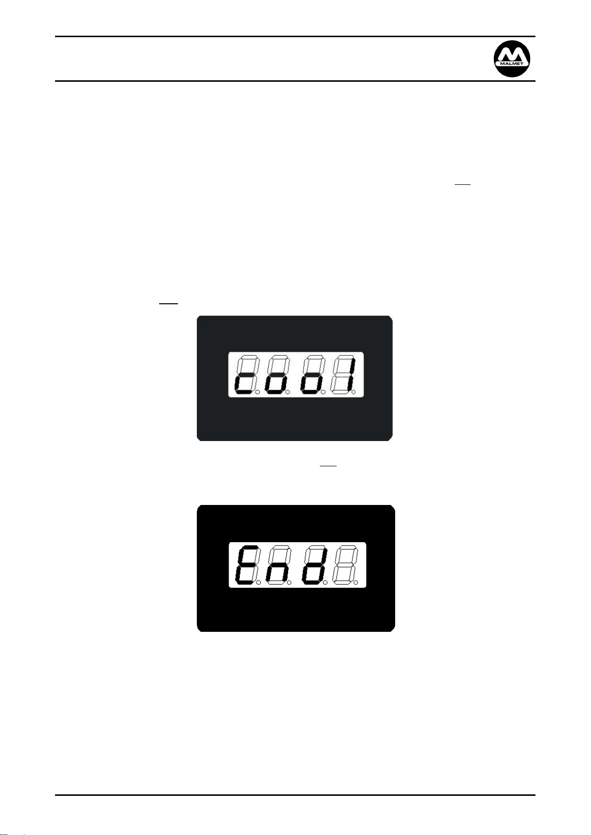
20. At the end of the cool down rinse, the display shows End. This will be displayed until the door is re-
opened. If the chamber temperature is above the safe opening temperature the display shows “HOT”
and access is restricted until temperature has reduced to a safe level.
21. If the device is not used, the device steam generator temperature will be kept at 85°C-90°C for a period
of 15 minutes. After 15 minutes, if the device is still not used it will enter into idle mode and the
elements will only come on at 50°C and rise to the temperature of 90°C repeatedly until the cycle is
started again.
Issue 3 Page 16 04/10/2019
Page 17

Malmet Bedpan / Urinal Bottle Washer Disinfector (ES-D)
Green LED Display
Door open
OPEN
Door closed
Shut
Steam generator fill
Fill
Cycle ready
rdY
Cycle started
rinS
Detergent
dEt
Pause
PAUS
Disinfection cycle started
(flashing)
90˚C
Disinfection temperature reached
‘actual’ temp ˚C
Cool down final rinse
cool
End of cycle
End
Chamber above safe opening temperature
Hot
Yellow LED illuminates on control panel
Overflow
2 flashing green LED in activation area
(8 seconds)
Cycle can be started
Detergent Model with Hands Free Operation
Operation, Maintenance and Installation Manual
Display Board
Issue 3 Page 17 04/10/2019
Page 18
Malmet Bedpan / Urinal Bottle Washer Disinfector (ES-D)
Detergent Model with Hands Free Operation
Operation, Maintenance and Installation Manual
Section B – Device Maintenance
A qualified person should carry out all maintenance, preventative or breakdown. Failure to
comply with this condition may result in unsafe conditions.
The Malmet Bedpan / Urinal Bottle Washer Disinfector is self-cleaning, however proper care should be
taken to ensure that the device is cleaned and maintained in accordance with the maintenance instructions
for Malmet Bedpan / Urinal Bottle Washer Disinfectors and in accordance with all other regulatory and
common sense practices.
Preventative Maintenance Schedule
Daily Maintenance (Operator or Maintenance Technician)
a) Wipe out the inside of the door and chamber with warm water and detergent. A wipe with
disinfectant is also desirable.
b) Wipe over outside stainless steel panels with a stainless steel cleaner.
c) Wipe the front control panel with a soft cloth and mild detergent as necessary. Care should be
taken not to damage the digital display or to activate a cycle.
d) Check level in detergent bottle, replenish as necessary.
e) Check Bedpan Wash Spinner turns freely by manually spinning nozzle.
f) Check spray nozzles are not blocked, insert a small pin into the orifice of the spray nozzle to ensure
no blockages are present. If a build up or blockage is noticed please have a technician clean nozzles
as per Bi-Monthly Maintenance to ensure adequate performance.
g) Visually inspect for signs of leaking fluid from the device, as these may pose a pathogenic risk.
Inspect around the chamber door, beneath the device and service connection points. If a spill or
leak is observed, clean up as per the facility’s infection control procedure and notify a maintenance
technician to fix the cause of the leak.
Bi-Monthly (Maintenance Technician)
WARNING! 240 VOLTS
ISOLATE DEVICE FROM ELECTRICAL SUPPLY BEFORE SERVICING
HOT SURFACES!
ALLOW DEVICE TO COOL PRIOR TO COMMENCING SERVICE WORKS
a) Inspect for steam or fluid leaks, tighten unions, hose clamps and glands where necessary.
b) Remove and clean out all sprays and bottle hooks (unscrew from inside chamber). Clean in
ultrasonic cleaner if available; use an appropriate sized Oxy-Acetylene tip cleaner pin to clean out
spray nozzle orifices.
c) Remove level probe in steam generator tank and clean off any build-up of residue.
d) Remove temperature probes in steam tank and chamber and clean off any build-up of residue.
e) Visually inspect build-up of residue in steam tank, especially in areas of poor water quality.
f) Check filter in the water inlet solenoid valve and clean as necessary.
g) Check and tighten, if necessary, all electrical connections.
Issue 3 Page 18 04/10/2019
Page 19
Malmet Bedpan / Urinal Bottle Washer Disinfector (ES-D)
Detergent Model with Hands Free Operation
Operation, Maintenance and Installation Manual
Stainless Steel Maintenance/Care
Under normal usage, stainless steel products require regular cleaning with a soft clean rag moistened with
a mild detergent followed by a water moistened clean rag and then a dry rag.
The #4 satin finish stainless steel should be protected against Muriatic acid and caustic or abrasive
materials and harsh cleaning detergents. In the event such agents cause discoloration, polish with a
stainless steel cleaner such as 3M Stainless Steel Cleaner & Polish and 3M Scotch Brite pad.
Recommended Preventative Maintenance Schedule
To be performed THREE TIMES YEARLY.
WARNING! 240 VOLTS
ISOLATE DEVICE FROM ELECTRICAL SUPPLY BEFORE SERVICING
HOT SURFACES!
ALLOW DEVICE TO COOL PRIOR TO COMMENCING SERVICE WORKS
a) Remove top and side panels and front bottom panel.
Note: Panel removal
i) Remove 2 self-tapping screws on the top panel.
ii) Push the side panel back then lift up to remove.
iii) Remove 2 x 3/16” screws from bottom front panel.
b) Remove three sprays, two bottle hooks and rotary nozzle from inside the chamber – check that the
holes are clear. Clean as required use an appropriate sized Oxy-Acetylene tip cleaner pin to clean
out spray nozzle orifices (hold under tap and pressurise or clean in ultrasonic cleaner). In areas
with hard water or high minerals in water supply, chemical de-scaler may be the quickest and
easiest means to remove built up deposits. Replace sprays and bottle hooks.
c) Start cycle and check that cold water pump is working, 17 seconds of the cycle.
d) After ascertaining that the pump is working properly, check the solenoid operation in the cold
water tank. Check steam sensor (steam generator) maintenance.
e) Make sure the solenoids are completely shutting off and levels are not creeping up, if so, clean
and/or replace the solenoid.
f) Tighten the screws retaining the pan rack on the door.
ONLY IF NECESSARY AFTER VISUAL CHECK
g) Clean dust and grit off components.
Malmet will make available on request circuit diagrams, component parts lists, descriptions, calibration
instructions, or information which will assist the user’s appropriately qualified technical personnel to repair
those parts of the device.
Malmet recommends performance qualification shall be performed annually
Issue 3 Page 19 04/10/2019
Page 20

Malmet Bedpan / Urinal Bottle Washer Disinfector (ES-D)
Detergent Model with Hands Free Operation
Operation, Maintenance and Installation Manual
Safety Checks
After servicing or repair the device shall be checked to confirm correct cycle operation and that the device
is in a safe operating state before being returned to service.
Door Safety Test
To check the correct functionality of the door safety and position sensors, open and close the door using
the manual door open button. During operation the device will conduct a self-check for correct operation
of these switches. Once complete, check door is firmly closed and is flush with outer panel and then press
the cycle “Start” button. If the wash pump starts, the self-check has been completed successfully and the
door safety devices are functioning correctly.
Cycle Operation Check
After completion of the required checks above, a cycle operation check is to be completed. Run the device
through a complete cycle ensuring correct sequence of operation as per page 12 of this manual. Inspect for
fluid leaks from around the chamber door, rear service connections and beneath the device. If no faults are
found during the inspection, and the device displays no faults at end of the cycle the device is fit for return
to operation.
Post Maintenance and Repair of Electrical Systems
Additional to the above safety tests if any repair or service work has been carried out that could affect the
electrical safety of the device; it must be inspected and tested as per the requirements of AS/NZS3760 prior
to being returned to service.
If device fails any of the above tests it is not safe for operation, and cannot be put into service
until the cause of the fault has been rectified and successful completion of tests.
Replacement of Safety Devices
The following safety devices must be replaced and tested by a Malmet trained technician, failure to do so
may impair the protection by the device.
Door Actuator
Door Micro Switch
Element Thermal Cut-out
Information on replacement of these devices can be found in the Service Technicians Manual.
Issue 3 Page 20 04/10/2019
Page 21

Malmet Bedpan / Urinal Bottle Washer Disinfector (ES-D)
Detergent Model with Hands Free Operation
Operation, Maintenance and Installation Manual
Fault Finding Guide
The device is controlled by a micro-processor. The processor has fault detection capability and indicates
faults by code on the digital display; Diagram B1 (below) shows an example of fault code displayed.
Diagram B1
(Fault 01 indicated)
Please see table in Appendix A for a full list of fault codes along with their description and possible cause.
Note: If a fault is displayed on the LED display, turn device off and turn it back on, press START to try to
complete a cycle. If a fault persists contact a Service Technician. Record the fault code that has
appeared for the Service Technician.
Table B1 indicates these faults. For a more detailed description of these fault conditions see
Appendix A – Faults.
Issue 3 Page 21 04/10/2019
Page 22

Malmet Bedpan / Urinal Bottle Washer Disinfector (ES-D)
Fault 01
Door Open Fault – Not confirmed door closed
(i.e. door switch still indicates open)
Cause
Door limit switch stuck out / broken
Fault 02
Wash / Disinfection Cycle Time Out
(taking too long to complete cycle)
Cause
Steam leak
Final rinse solenoid stuck open
Faulty temperature sensor hot water tank
Blown element leg
Steam condensate leaking cold water into chamber
Faulty temperature sensor - chamber
Fault 03
Faulty Hot Water Probes
(high indicates water, but low does not indicate water)
Cause
Faulty water level probe
Fault 04
Door motor activation time out
(taking too long to close or open door)
Cause
Faulty door actuator
Door axle bar sticking
Fault 06
Hot water tank fill time exceeded
(high level not reached during pre-fill, resulting in time out)
Cause
Faulty fill solenoid
Faulty water level probe
Cold water tank empty or not filling quick enough
Low water pressure
Fault 07
Hot water tank low water level sensed during cycle
Cause
Faulty water level probe
Cold water tank empty or not filling quick enough
Leaking tank or hose
Element stuck on
Condensing coil blocked
Fault 08
Door closure fault – not confirmed door open
(door switch still indicates closed)
Cause
Door limit switch stuck on
Detergent Model with Hands Free Operation
Operation, Maintenance and Installation Manual
Appendix A – Faults
Following is list of fault conditions and most possible causes.
Issue 3 Page 22 04/10/2019
Page 23

Malmet Bedpan / Urinal Bottle Washer Disinfector (ES-D)
Fault 09
Failed to reach disinfection start temperature, resulting in time out
Cause
Steam leak
Final rinse solenoid stuck open
Faulty temperature sensor hot water tank
Blown element leg
Steam condensate leaking cold water into chamber
Faulty temperature sensor chamber
Door not reaching interlocking micro switch
Door not fully closed
Over temperature board (power to element open circuit)
Element over temp protection manual reset thermal cut-out switch open circuit
Fault 10
Disinfection temperature not maintained, resulting in cycle time out
Cause
Steam leak
Final rinse solenoid stuck open
Faulty temperature sensor hot water tank
Blown element leg
Steam condensate leaking cold water into chamber
Faulty temperature sensor - chamber
Fault 12
Hot tank short temperature sensor
Cause
Faulty temperature sensor steam generator
Fault 13
Hot tank open circuit temperature sensor
Cause
Faulty temperature sensor steam generator
Fault 14
Disinfection chamber short circuit temperature sensor
Cause
Faulty temperature sensor - chamber
Fault 15
Disinfection chamber open circuit temperature sensor
Cause
Faulty temperature sensor - chamber
Fault 30
dEt
Insufficient detergent last wash
Cause
Empty detergent bottle
Faulty detergent pump
Blocked detergent line
Fault 31
HEAt
Disinfection temperature not maintained on 2nd probe
Cause
Steam leak
Final rinse solenoid stuck open
Faulty temperature sensor hot water tank
Blown element leg
Steam condensate leaking cold water into chamber
Faulty temperature sensor – chamber
Faulty temperature sensor – chamber 2
Fault 32
CFSd
Unsupported fault
(cycle did not follow supported order)
Cause
Interrupted power
Processor glitch
Fault 33
bLOC
Chamber blockage present – flood sensors
(Sensors are detecting a build-up above the bottom of the door inside the chamber)
Cause
Blocked trap
Blocked / backed up drain
Dirty sensors
Fault 34
dEtH
Extra detergent injected last wash
(the volume of detergent injected during the cycle was greater than necessary)
Cause
Faulty flow meter
Faulty detergent pump relay
Failed check valve
Detergent Model with Hands Free Operation
Operation, Maintenance and Installation Manual
Issue 3 Page 23 04/10/2019
Page 24
Malmet Bedpan / Urinal Bottle Washer Disinfector (ES-D)
Fault 35
PobE
Temperature discrepancy – temperature difference >5˚C between probes
Cause
Faulty temperature sensor/s
Fluctuating temperatures
Fault 38
FPri
Failed priming – exceeded allowed priming attempts
Cause
Detergent bottle not changed
Detergent line split / leaking
Flow meter faulty
Check valve failed
Detergent Model with Hands Free Operation
Operation, Maintenance and Installation Manual
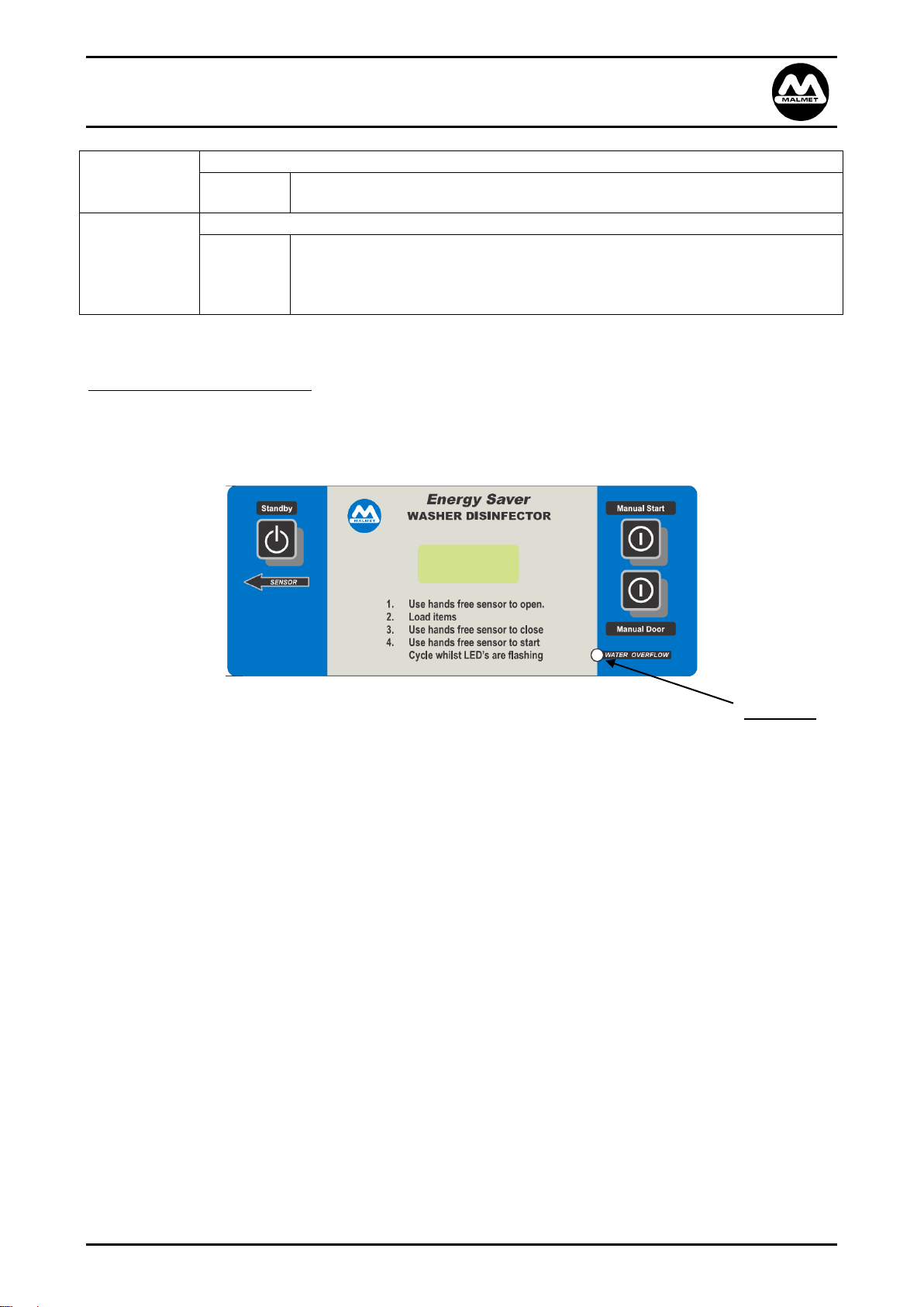
Cold Water Overflow Indication
The yellow LED is used for cold water tank overflow.
Overflow is indicated by a STEADY ON LED, whenever the overflow level is detected.
Should the cold water tank overflow into the soil line the water overflow YELLOW LED will illuminate.
Issue 3 Page 24 04/10/2019
Page 25
Malmet Bedpan / Urinal Bottle Washer Disinfector (ES-D)
200m
Detergent Model with Hands Free Operation
Operation, Maintenance and Installation Manual
Appendix B – Additional Faults not detected by micro-processor
Faults
These are other faults that may occur which the micro-processor cannot detect (however, it may indicate a
fault with the following conditions).
Not washing bedpans
1. Check that the cold water pump is working.
2. Check that there is cold water in the tank.
3. Check sprays.
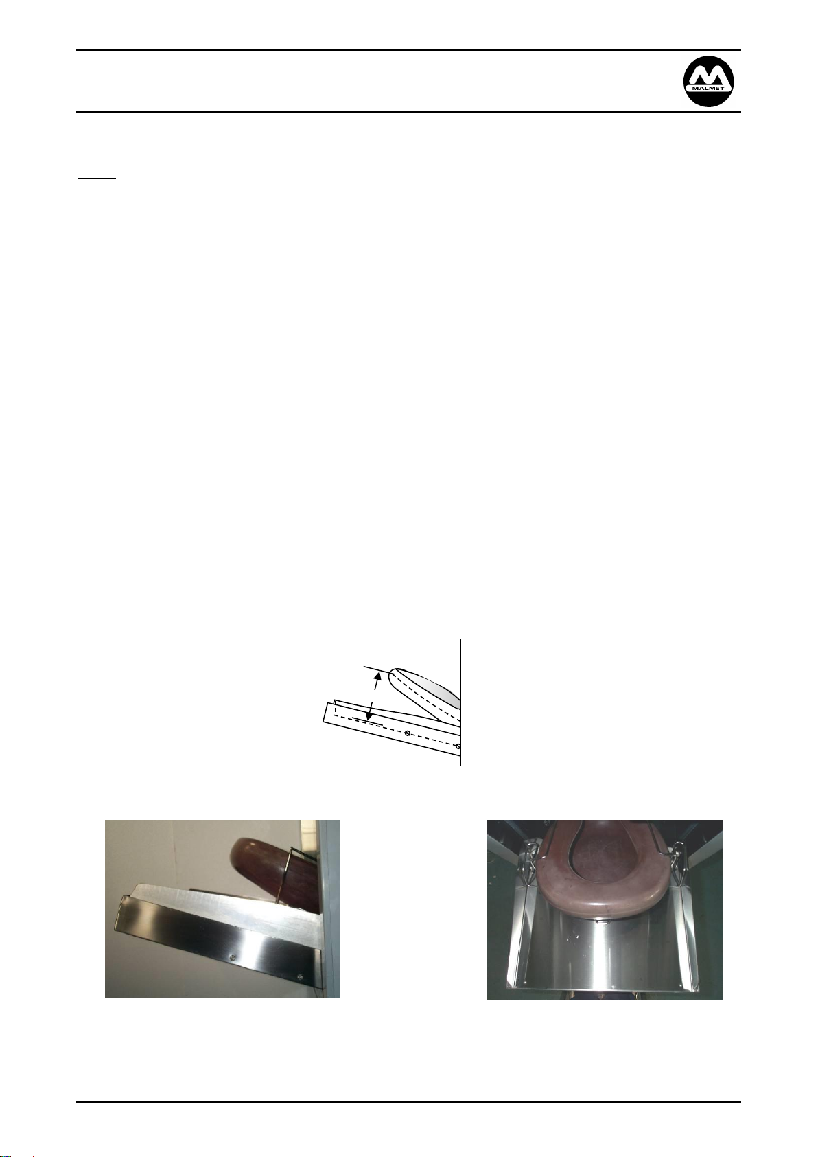
4. Check bedpan position in door cradle. (Diagram B2)
No power to control box
1. Check main power.
2. Check power to control boards.
Leaking water onto the floor
1. Check all hose fittings.
2. Check water levels and water probes.
3. Check pump seals.
4. Check door seal.
Loading Bed Pans
Diagram B2
Side View Top View
Diagram B3 Diagram B4
Issue 3 Page 25 04/10/2019
Page 26
Malmet Bedpan / Urinal Bottle Washer Disinfector (ES-D)
REF DRG: 91-2127_6
Detergent Model with Hands Free Operation
Operation, Maintenance and Installation Manual
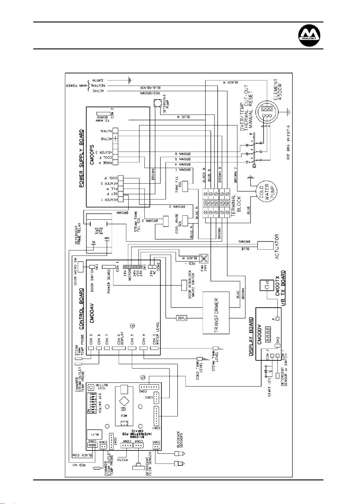
Electrical Diagram – 20 Amp Models (ES915)
Issue 3 Page 26 04/10/2019
Page 27
Malmet Bedpan / Urinal Bottle Washer Disinfector (ES-D)
REF DRG: 91-2128_6
Detergent Model with Hands Free Operation
Operation, Maintenance and Installation Manual
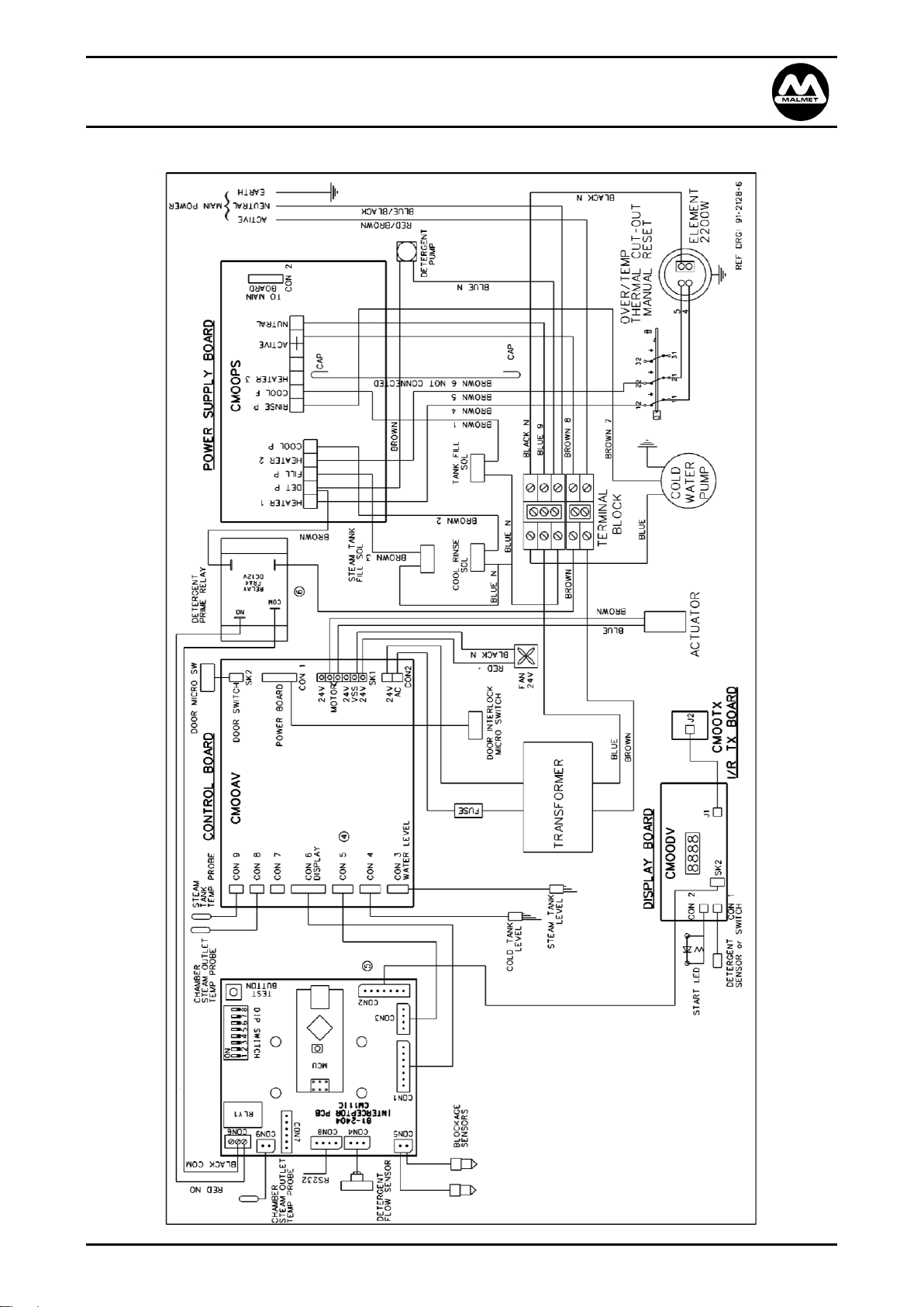
Electrical Diagram –10 Amp Models (ES935)
Issue 3 Page 27 04/10/2019
Page 28

Malmet Bedpan / Urinal Bottle Washer Disinfector (ES-D)
Detergent Model with Hands Free Operation
Operation, Maintenance and Installation Manual
Hydraulic Circuit Diagram - ES915/935
Issue 3 Page 28 04/10/2019
Page 29

Malmet Bedpan / Urinal Bottle Washer Disinfector (ES-D)
Detergent Model with Hands Free Operation
Operation, Maintenance and Installation Manual
Section C – Device Installation
To avoid problems with this device, these Installation Guidelines should be followed.
Installations must be carried out by a qualified and licenced tradesperson.
All devices must be earthed.
The device must be affixed to the building structure to ensure mechanical stability prior to use. The
device can be affixed to the building structure via the holes provided in the device feet, or use of an
appropriately rated appliance safety strap.
Prior to installation of the device, services as noted are to be provided by the facility. It is not the
responsibility of Malmet to provide these service connections.
Overcurrent protection device-
A 10A circuit breaker or fuse for 10A rated models must be installed in the building installation.
A 20A circuit breaker or fuse for 20A rated models must be installed in the building installation.
Risk Assessment
It is recommended a risk assessment is conducted by the user both prior to and after installation and any
risks identified mitigated to an acceptable level using the hierarchy of control;
https://commons.wikimedia.org/w/index.php?curid=55610678
Issue 3 Page 29 04/10/2019
Page 30

Malmet Bedpan / Urinal Bottle Washer Disinfector (ES-D)
MODEL
COLD WATER
SOIL LINE
ELECTRICAL
ES915
GB¾ Male
100mm ‘S’ or ‘P’ Trap
240V 1 phase @ 20 Amps
50 hertz
ES935
GB¾ Male
100mm ‘S’ or ‘P’ Trap
240V 1 phase @ 10 Amps
50 hertz
Detergent Model with Hands Free Operation
Operation, Maintenance and Installation Manual
Handling
Weights of Device: Net: 92 kg Shipping: 110 kg Shipping with crating: 151 kg
Handling of the device to installation site must be with a fork lift or hand pallet truck. After unpacking the
device, remove the 4 screws holding the device to the pallet. 2 people will be required to manoeuvre the
device off the pallet. The device can then be placed into position by fork lift or hand pallet truck.
Disposal of Packaging
Please dispose of packaging as per facility procedures or local government requirements.
Service Connections
Water and Drain waste services
Note: Plumbing service connection must comply with AS/NZS3500
Issue 3 Page 30 04/10/2019
Page 31

Malmet Bedpan / Urinal Bottle Washer Disinfector (ES-D)
660
Control Panel
365
‘S’ or ‘P’ Trap
(‘P’ Trap shown)
Chamber
Detergent
Door
Cold Water
Mains Inlet GB¾”
595
1305
100
Cold Water
Tank
1245
Power Supply
Lead 20 Amp
Detergent Model with Hands Free Operation
Operation, Maintenance and Installation Manual
Dimensions and Service Entry Points
Front View Rear View
Left View Right View
Issue 3 Page 31 04/10/2019
Diagram C1
Page 32

Malmet Bedpan / Urinal Bottle Washer Disinfector (ES-D)
Detergent Model with Hands Free Operation
Operation, Maintenance and Installation Manual
Electrical
The Malmet Bedpan / Urinal Bottle Washer Disinfector requires only single phase power (240 Volts 50
Hertz). The device must be installed and serviced to national wiring rules AS/NZS 3000.
Note: Mains power connection
An ISO switch or circuit breaker must be included in the installation. (Not supplied by Malmet)
It must be suitably located and easily reached, approximately 1500mm above floor level adjacent
to device. The 1.7m mains power lead exits the device approximately 1200mm above floor level on
the right hand side of the device.
It must be marked as the disconnecting device for the equipment.
It must have contact disconnection of all poles to provide full disconnection.
Ensure isolator is suitably placed so device will not obstruct safe access to the isolator once
installed.
10 Amp Device – To be hard wired to a lockout ISO switch or Circuit breaker.
Switch must be wired to 10A max circuit breaker at main switch board
20 Amp Device – To be hard wired to a lockout ISO switch or Circuit breaker.
Switch must be wired to 20A circuit breaker at main switch board
10 and 20 Amp devices are supplied with an electrical power lead for hard wiring to an isolation
switch.
If the supply lead is damaged, it shall be replaced by Malmet; its authorised service agent or
similarly qualified person in order to avoid hazard.
Mains power ISO switch or circuit breaker must be in an accessible position so device can
be isolated from mains power during service.
ALL DEVICES MUST BE EARTHED.
The maximum permissible system impedance Zsys:
Z = 0.220 Ohm + j 0.137 Ohm (0.220 Ohm + 437 μH)
Issue 3 Page 32 04/10/2019
Page 33

Malmet Bedpan / Urinal Bottle Washer Disinfector (ES-D)
Detergent Model with Hands Free Operation
Operation, Maintenance and Installation Manual
Post Installation Precautions
a) Before switching the device on make sure the water tap is on.
b) Turn on the power at the isolation switch and press the standby button on the front display. The
digital display will illuminate.
c) The water in the steam tank is heated to the required temperature. In the first instance there will be a
delay as cold water is heated to 90°C.
This delay will not re-occur while the power remains switched on.
d) Flush approximately ½ a litre of water down the cold-water tank overflow pipe. This will fill the ‘S’
Trap at the hose junction and prevent steam coming back up into the cold water tank.
e) The device will display ‘rdY’ (ready) when the water levels are reached.
Note: DO NOT USE THE DEVICE WITHOUT THE WATER SUPPLY TURNED ON.
Issue 3 Page 33 04/10/2019
Page 34

Malmet Bedpan / Urinal Bottle Washer Disinfector (ES-D)
Model
Placement
Access
Required
Device Dimensions
Height (mm)
Width (mm)
Depth (mm)
ES915 models
ES935 models
Freestanding
Both Sides
1305
595
660
Please allow sufficient room for servicing purposes. Recommended space requirements 200mm on
either side and 150mm at the rear of the device.
Detergent Model with Hands Free Operation
Operation, Maintenance and Installation Manual
Positioning of Bedpan Washer Disinfector
New Buildings
Service connections are normally pre-placed after planning and consultation with all interested parties.
Installation is by connection to the services provided.
As the soil line (sewerage outlet) is the least flexible of all the connections, this usually influences the
decision as to where to place the Bedpan / Urinal Bottle Washer Disinfector. If an existing soil line can be
utilised this will represent a cost saving.
The Bedpan / Urinal Bottle Washer Disinfector is supplied with either a ‘S’ or ‘P’ Trap as nominated by the
Purchaser. The ‘S’ Trap connects through the floor and the ‘P’ Trap connects through the back wall. The
trap section is easily removed if the wrong trap has been ordered. Refer to Diagram C2 for trap
connections.
Potential electromagnetic or other interference between other EQUIPMENT and other devices can
possibly affect the Infra-red hands free operation sensor. It is advisable to check all the equipment
and devices in the intended installation area that have infra-red operation. Electromagnetic
interference can be prevented by installing the device in non-patient areas of the facility (or
similar).
Note: Bell Ends can be cut off to suit
Diagram C2
FOR REASONABLE CONNECTION WORKING SPACE ALLOW 150-200mm FROM REAR OF DEVICE TO WALL
Issue 3 Page 34 04/10/2019
Page 35

Malmet Bedpan / Urinal Bottle Washer Disinfector (ES-D)
FREE STANDING
‘S’ TRAP PIPE POSITIONING
FREE STANDING
‘P’ TRAP PIPE POSITIONING
The centre of the soil line to receive the ‘S’ Trap
should be approximately 272mm from the back
wall. To allow for normal recommended
minimum service access, space soil line
600/700mm from side wall.
If space restrictions do not allow for
recommended side service access, Malmet
suggest preference be given to providing the
most space available on the right hand side as
you look at the front of the device. This will
ease any difficulty in servicing the steam tank
element and probe.
The centre of the soil line to receive the ‘P’ Trap
should be approximately 410mm from the floor
when the device is positioned 150mm from the
wall. Because this pipe is graded to 5° this
measurement will vary as the device is installed
closer or further away from the back wall.
Detergent Model with Hands Free Operation
Operation, Maintenance and Installation Manual
The device is 600mm wide and the centre of the trap is 300mm from each side.
Steam Venting
No external vent pipework is required as the device is designed to condensate all visible steam within the
device.
Issue 3 Page 35 04/10/2019
Page 36
Malmet Bedpan / Urinal Bottle Washer Disinfector (ES-D)
Detergent Model with Hands Free Operation
Operation, Maintenance and Installation Manual
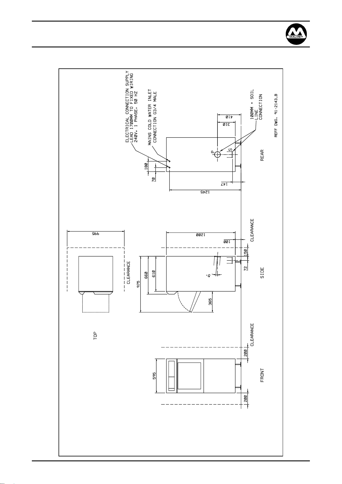
Installation and Service Connection Layout Details
Issue 3 Page 36 04/10/2019
Page 37
Malmet Bedpan / Urinal Bottle Washer Disinfector (ES-D)
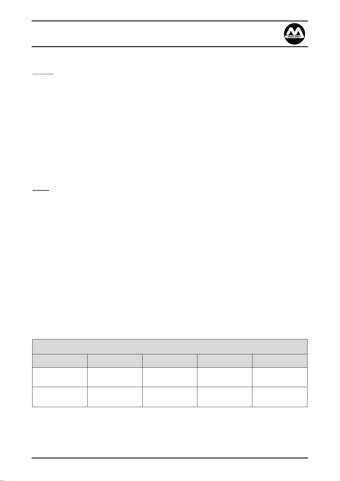
POWER AND WATER CONSUMPTION DATA
Model
Avg Cycles per/Hr
Avg Cycle min/sec
Avg kWh per cycle
CW Avg Lt per cycle
ES915S-D / ES915P-D
20 Amp Model
11
5.3
0.300
36
ES935S-D / ES935P-D
10 Amp Model
7.7
7.5
0.236
35.5
Detergent Model with Hands Free Operation
Operation, Maintenance and Installation Manual
Plumbing
Soil Line
There is no high temperature water discharged from this device so no special high temperature pipework is
necessary.
Soil line connection is by a pan collar or other preferred method. If the bell end on the polyethylene
moulded trap is not required it can easily be cut off to provide a straight pipe connection.
Level the device by using the flanged screw in legs and if possible maintain approximately 100mm floor
clearance for ease of floor cleaning. Malmet recommends fixing some of the leg flanges to the floor via
stainless self-tapping screws, dyna bolts or similar to prevent sideways movements and damage to services
and soil line connections.
Soil line to protrude from the floor or wall at a minimum of 100mm.
Water
ONLY COLD WATER CONNECTIONS IS REQUIRED. The device can be connected to any potable mains
pressure cold water supply as an AIRBREAK is incorporated in the design of the cold water tank.
The water supply should be connected to an isolating valve or cistern stopcock placed approximately
1200mm from the floor to the left-hand side of the device (preferably not behind the device).
Minimum water pressure: 100kPa
Recommended nominal flow rate: 10L/Min
Recommended Maximum Water Hardness: 2.5mmol/L
Recommended Water pH: 6.5-8.5
Recommended Maximum Water Conductivity: 850μS/cm
Technical Specifications
Note: Values may change due to operating and supply service conditions.
Issue 3 Page 37 04/10/2019
Page 38
Malmet Bedpan / Urinal Bottle Washer Disinfector (ES-D)
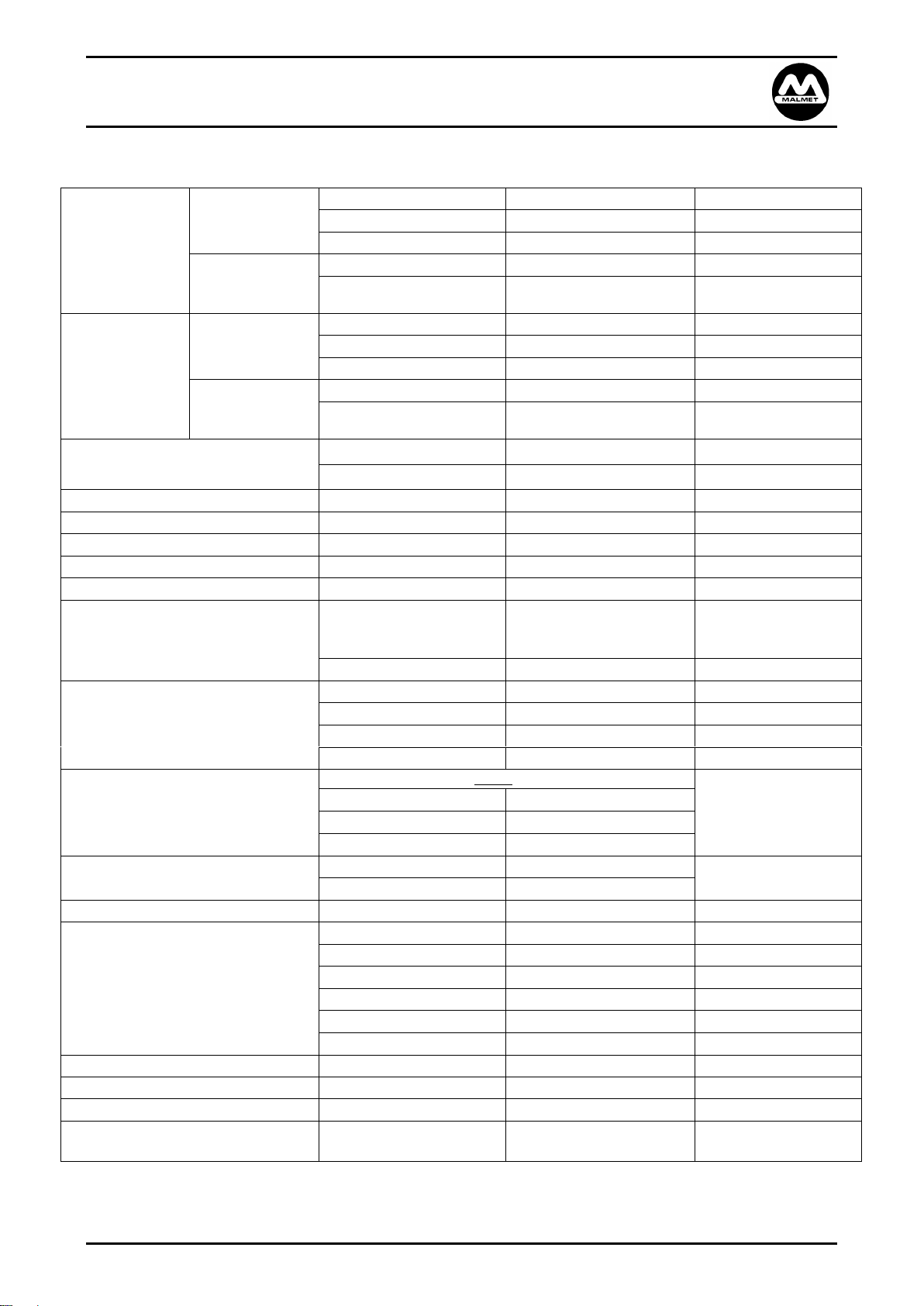
ES-D915 Models
Electrical Rating
Volts
240V
APPROVALS
Phase / Hz
1 ph / 50 Hz
Amps
20 Amps
Element
Rated
4.5kW
Overtemp protection
3 pole Thermal cut-out switch
Set point 115°C Manual reset
ES-D935 Models
Electrical Rating
Volts
240V
Phase / Hz
1 ph / 50 Hz
Amps
10 Amps
Element
Rated
2.2kW
Overtemp protection
3 pole Thermal cut-out switch
Set point 115°C Manual reset
Environment Operating Conditions
Temperature
+10°C to +25°C
Relative Humidity
+30% to 70%
Door Actuator
Type LA12 Self-Locking
24VDC
Door Micro Switch
531C-3H
15A/250V
Fuse: Transformer
Cylinder type
F3.15AL 250V
Fuse F1 : Power supply PCB
Cylinder type
T315mA 250V
PCB (Printed Circuit Board)
Spray System
Main Wash
1 x Rotating 180° Nozzle
2 x Fixed 60° Nozzles
2 x Fixed 0° Nozzle
Cool Down
1 x Fixed 60° Nozzle
Wash Chamber
Material
1.2mm Stainless Steel
Design Life
Minimum of 10,000 Cycles
Total Chamber Volume
60 L Total Usable Chamber Volume
50 L
Loading Capacity
2 x Urinal Bottles and One (1) of the following:
•
Bed Pan & Lid
•
Commode & Lid
•
Small Commode & Lid
•
Small Slipper Pan & Lid
•
Large Slipper Pan & Lid
Soil line Connection
Type
‘S’ or ‘P’ Trap (6mm PE)
Complies to AS 2887 &
AS/NZS 3500.2:2003
Size
100mm ID
Backflow Prevention
Air Gap (RAG)
AS 2845.2 - 1996
Water Supply Cold
Potable Water
(Final Rinse Water)
pH
6.5-8.5pH
Water Hardness
<2.5mmol/L
Water conductivity
<850 μS/cm
Temperature
5 – 25°C
Pressure (Static)
100 – 400kpa
Nominal Flow Rate
10/L Min
Water Inlet Valve connection
Solenoid 240V
GB¾ Male
WRAS Certified
Hose – valve to Cold Water Tank
s/steel Braided
10mm
WRAS Certified
Principal Heavy Component
Main Wash Pump
11kg
Detergent
Malmet specific (5Lt)
Detergent concentrate Caustic
Alkaline
ARTG Class 1
Detergent Model with Hands Free Operation
Operation, Maintenance and Installation Manual
Device Specifications
Issue 3 Page 38 04/10/2019
Continued over page
Page 39

Malmet Bedpan / Urinal Bottle Washer Disinfector (ES-D)
Environment & Conditions for
Transport and Storage
Fragile
Keep away from rain
Do not stack
Temperature
-5°C to +50°C
Weights
Rounded up to the nearest Kilogram
Nett
Operating
Shipping
Shipping (Crated)
92kg
122kg
110kg
151kg
Dimensions (W x D x H)
595 x 660 x 1300 (mm)
710 x 790 x 1520 (mm)
710 x 790 x 1520 (mm)
Floor Loading at Each Support as viewed from
front of unit.
* Loadings are a guide only & will vary between
installations.
Front Left
Front Right
Rear Left
Rear Right
31kg*
33kg*
37kg*
21kg*
Detergent Model with Hands Free Operation
Operation, Maintenance and Installation Manual
Device Specifications Cont’d
Issue 3 Page 39 04/10/2019
Page 40

Malmet Bedpan / Urinal Bottle Washer Disinfector (ES-D)
Malmet Devices
Device Components
Parts & Labour
Structural Guarantee
2 Years from Date of Purchase
All other components
2 Years from Date of Purchase
Malmet Spare Parts
1 Year from Date of Purchase
Detergent Model with Hands Free Operation
Operation, Maintenance and Installation Manual
Warranty Statement
This warranty is provided, and operates in addition to, the statutory warranties Malmet (Australia) Pty Ltd
("Malmet") provides to any consumer under the Australian Consumer Law (if applicable) or by virtue of any other
applicable legislation.
Subject to the following conditions, we provide, from the date of purchase, the following warranty on Malmet devices
and spare parts for products manufactured by Malmet and sold in Australia:
•
Functional components found within the device to be defective in workmanship or material will be repaired or
replaced free of charge subject to the periods of warranty specified in the table below.
•
A decision regarding whether the defective components will be repaired or replaced will be determined at the
sole discretion of Malmet or its authorised agents or representatives.
•
The structural warranty covers any structural components within the device, which fail to perform their
intended function due to faulty manufacture or deterioration within the warranty period.
•
Parts replaced in devices under warranty are warranted for the balance of the original warranty period for
that device.
The installer is responsible for the correct installation, start up and demonstrating the operation of the product. They are also
responsible for issuing the relevant certificates of compliance (these may differ from state to state).
CONDITIONS AND EXCLUSIONS
•
Device must be installed and commissioned according to Malmet’s instructions (outlined in Malmet Operation,
Maintenance and Installation Manual) and operated to the purpose it was designed.
•
Device must be serviced as instructed in the Operation, Maintenance and Installation Manuals.
•
To the extent permitted by law, this warranty shall not cover damage, malfunction or failure resulting from accident, misuse
•
or misapplication, improper or unauthorised repair, neglect or modification or use of unauthorised replacement parts or
accessories, inclusive of detergent, or improper voltage. The warranty may be void if the serial number is removed or
altered.
•
Parts damaged in transit back to Malmet Leeton due to poor packaging could result in warranty claim being rejected in part
or in full.
•
Any part tampered with or which has been altered by unauthorised repairs and/or modifications will be
rejected under a warranty claim to the extent permitted by law (to the extent the Australian Consumer Law
applies, Malmet will assess the extent to which the tampering or unauthorised repairs contributed to the
failure).
•
Reasonable access must be allowed for maintenance. If any additional equipment is needed to provide access
to the device, this must be provided (and paid for) by the owner.
•
It is the owner's responsibility to provide safe access to the device. Malmet, or any of its authorised service agents, may
refuse to perform maintenance or warranty work if access is unsafe, as determined by Malmet or any of its authorised
service agents acting reasonably.
•
Should a warranty claim be rejected you will be advised in writing with a full explanation of our reasons.
Issue 3 Page 40 04/10/2019
Page 41

Malmet Bedpan / Urinal Bottle Washer Disinfector (ES-D)
Detergent Model with Hands Free Operation
Operation, Maintenance and Installation Manual
•
Malmet have a Warranty Claim Procedure that is fair to our customers and provides an efficient system of replacement
and/or repair of faulty parts. If at any time you believe we are not meeting our commitment to you please contact Malmet
Head Office via email: [email protected]
To the extent permitted by law, no responsibility will be accepted for outside elements including, but not limited to storms,
pest and vermin that may cause damage to the device.
To the extent permitted by law, no responsibility will be accepted for damage incurred as a result of, or incidental to, electrical
surges or brown outs or for any other consequential damages.
If there is no certificate of compliance for plumbing or electrical, Malmet reserves the right to refuse service on non-compliant
installations.
To the extent permitted by law, claims for damage to contents, carpet, ceilings, foundations or any other consequential loss
either direct or indirect resulting from, power spikes, incorrect operation, incorrect installation, faulty product or any other
cause, are excluded.
This warranty, and to the extent permitted by law, any warranties owed by Malmet under the Australian Consumer Law or
other applicable legislation, are not transferrable and cannot be sold, assigned or transferred in any other way from the
purchaser to any other person.
To the extent permitted by law, unauthorised use of any parts that were not supplied or approved for use in the applicable
device by Malmet will result in this warranty and any warranty claims applicable to that device being void.
Warranty labour (service work) shall not include devices located outside of city metropolitan areas of Melbourne, Sydney,
Adelaide, Perth and Brisbane. Costs outside these areas shall be borne by the owner. The owner shall be notified of this prior
to the warranty call out.
To the extent permitted by law, a charge will be made for work done or a service call made where:
There is no default apparent with the device, as determined by Malmet or its authorised representative or agent acting
reasonably.
The defective operation of the device is due to failure of electricity or water supply.
Defects are caused by neglect, incorrect application, abuse or by accidental damage of the device.
An unauthorised person has attempted to repair the device.
Harsh environmental situations including, but not limited to, water quality that may cause the water tank
damage cannot be covered under this warranty.
How to make a claim under this warranty
If you believe there is a defect in a device you have purchased from Malmet, you must notify Malmet in writing of such defect, by
sending an email (Notice of Defect) to [email protected] prior to the expiration of the applicable warranty period set out in
this warranty.
For the avoidance of doubt, Malmet must receive your Notice of Defect prior to the expiration of the warranty period.
To the extent permitted by law, Malmet will not reimburse you for any expense you incur in claiming or attempting to make a
claim for repair or replacement of a component under this warranty.
Issue 3 Page 41 04/10/2019
Page 42

Malmet Bedpan / Urinal Bottle Washer Disinfector (ES-D)
Date Purchased:
Warranty Expiry Date:
Sold To:
For Service Contact:
Detergent Model with Hands Free Operation
Operation, Maintenance and Installation Manual
Please complete details below:
PROOF OF PURCHASE
Please retain your proof of purchase (receipt, invoice or commissioning certificate is accepted).
E.&O.E.
In the interest of continued product improvement, Malmet reserves the right to alter specifications without notice.
AUSTRALIAN CONSUMER LAW DISCLAIMER (APPLIES ONLY TO THE EXTENT YOU ARE A ‘CONSUMER’ WITHIN THE MEANING OF THE
AUSTRALIAN CONSUMER LAW):
Malmet goods come with guarantees that cannot be excluded under the Australian Consumer Law. You are entitled to a
replacement or refund for a major failure and for compensation for any other reasonably foreseeable loss or damage. You are also
entitled to have the goods repaired or replaced if the goods fail to be of acceptable quality and the failure does not amount to a
major failure
Issue 3 Page 42 04/10/2019
Page 43

BEDPAN INSERTION
Refer Page 9 in the Operation, Maintenance and
Installation Manual.
INSERT THIS END OF
BEDPAN FIRST
STANDARD SLIPPER PAN INSERTION
Pan must be firmly pushed down and locked into
rack.
Refer Page 9 in the Operation, Maintenance and
Installation Manual.
INSERT THIS END OF
SLIPPER PAN FIRST
Front Display
Panel
Infra Red Beam
LED’s
OPERATING DEVICE
1. OPEN DOOR – BREAK BEAM WITH CLOSED FIST or PAN/BOTTLE
2. LOAD PAN & BOTTLES AS PER INSTRUCTIONS (Page 9)
3. CLOSE DOOR & START CYCLE - BREAK BEAM WITH CLOSED FIST
a. DOOR WILL CLOSE Device displays rdY
b. BREAK BEAM within 8 seconds with CLOSED FIST and cycle will start.
If not broken within 8 seconds, beam must be broken TWICE to re-open.
E & O E
In the interest of continued product improvement, Malmet (Australia) Pty Ltd reserves the right to alter specifications without notice
MALMET ES-D BEDPAN /URINAL BOTTLE
WASHER DISINFECTOR QUICK REFERENCE
GUIDE
For complete instructions please refer to the
Operation, Maintenance and Installation manual for this device
Page 44

Manufactured by
Malmet (Australia) Pty Ltd
ABN 95 001 717 791
www.malmet.com.au
P/N 91-2144
 Loading...