


FORM 97140090
INSTALLATION INSTRUCTIONS
Ignition Model #35496
CAUTION: CAREFULLY READ INSTRUCTIONS BEFORE PROCEEDING. NOT LEGAL FOR USE OR SALE ON POLLUTION CONTROLLED VECHICLES
OVERVIEW
ACCEL Ignition Model 35496 is intended for use with Harley-Davidson® Evolution® type motorcycle engines. The Model 35496 replaces the original equipment (OE) electronic ignition system on 1978-99 models. The unit mounts in the gear case cover and uses the standard H-D® timing rotor. It can also be used on earlier models with breaker points and mechanical advance.
The Model 35496 offers adjustable advance, adjustable RPM limit settings in 100 RPM increments, and switch selectable single or dual fire modes. Single fire mode improves starting, reduces the occurrence of backfiring at low RPM, and improves power at high RPM. A red status LED flashes when the engine reaches top dead center (TDC) and allows easy static timing. The status LED also provides diagnostic information. A green VOES LED illuminates when the VOES (vacuum switch) input is active.
AVOIDING HEAT RELATED FAILURES
Heat kills electronics. The Model 35496 uses electronic devices rated for operation at 105 deg C (221 deg F), the highest rating available. The unit can tolerate somewhat higher temperatures, but exposure to temperatures above 125 deg C (257 deg F) will greatly reduce life expectancy. We sometimes see problematic applications where several module failures have occurred. The failure mode is a classic thermal intermittent where the module stops firing one cylinder when it gets hot. We have found that these problematic applications share one or more of the following characteristics:
•VOES switch removed or non-functional. All street driven engines require vacuum advance. Without vacuum advance at idle and part throttle, thermodynamic efficiency is reduced and engine temperatures increase significantly.
•Improper carburetor jetting resulting in lean air/fuel ratio (AFR). A lean AFR will cause the engine to run very hot. All performance engine modifications necessitate carburetor rejetting. Carburetors are never correctly jetted out-of-the-box. The only practical means of correctly jetting a carburetor is to test the motorcycle on a chassis dyno equipped with an exhaust gas sniffer.
•Lack of an oil cooler on a 95 CID or larger engine.
•Exhaust pipe without heat shield in close proximity to the nose cone. If any of the above applies to your application, the Model 35496 may be exposed to excessive temperatures resulting in reduced life expectancy. Use an infrared thermometer to check the module temperature.
INCLUDED AND ADDITIONAL REQUIRED PARTS
All units include a parts bag with crimp terminals for coil and VOES hookup.
FL series Big-Twin® models manufactured prior to 1985, FX series BigTwin® and XL Series Sportster® models manufactured prior to 1984, all Sportster® 1200S models, and all models with original equipment breaker points will require H-D® timing rotor P/N 32402-83 or an equivalent aftermarket part.
INSTALLATION
1. Turn off the ignition switch and disconnect the battery ground cable before proceeding.
2. Refer to Figure 1. Remove gear case cover plate and mounting hardware. You may have to drill out two rivets that hold the cover (reassemble with supplied self-threading screws). Remove the sensor plate or breaker points. Make sure that the correct H-D® P/N 32402-83 timing rotor is installed.
3. You can completely remove the OE ignition harness and external module (1980 and later models) if desired. However, you must disconnect all OE wires from the coil except the white/black wire from the engine stop/run switch.
4. Install the Model 35496 unit. Wrap one turn of electrical tape around the end of the protective wire harness sleeve. This will compress the sleeve and allow you to easily feed it through the cable exit hole in the gear case cover. The tape will also keep the sleeve end from fraying. You will have to enlarge the hole with a drill on early models and some Sportsters®.
5. Rotate the unit and then place it into position as shown in Figure 2. Be careful to avoid damage to the black plastic Hall Effect sensors on the bottom of the unit.
6. Route the wiring harness along the side of the unit and install the mounting standoffs as shown in Figure 3A for Big Twin or 3B for Sportster® models. Do not fully tighten the standoffs or install the outer cover plate until after the static timing procedure.
Figure 1 - Feeding Harness Through Exit Hole
ACCEL IGNITION www.accel-ignition.com 1

Figure 2 - Installing Unit (Note Orientation)
7.Route the wire harness along the frame tubing to the ignition coil. Make sure that the harness is clear of hot exhaust areas and cannot chafe against sharp edges. Secure the harness with nylon cable ties.
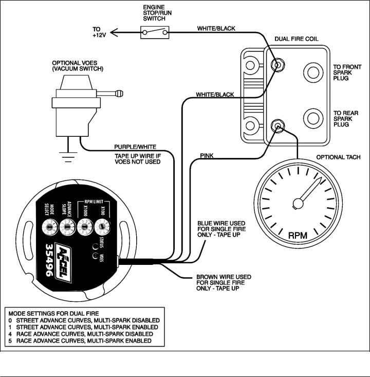
8.Refer to the appropriate wiring diagram. Use the dual fire hookup shown in Figure 4 if you have an OE coil or other coil with two primary terminals. Use the single fire hookup in Figure 5 if you are installing an aftermarket coil with three primary terminals. Use appropriate crimp terminals for coil and VOES hookup. With the exception of the tachometer and rear coil section (single fire only), standard H-D® wire color codes are used. Tape up any unused wires.
9.Install the supplied Weather Pack connector set on the brown tachometer wire as shown. If a tachometer is not used, seal the end of the mating plug with silicone RTV and use it as a protective cover. Use a proper Weather Pack crimping tool or solder the terminals.
10.Single Fire Tach Hookup. If your motorcycle had a tach before installation of the ACCEL module, the tach was connected to the pink coil wire. When you connect the tach direct to the ACCEL module as shown in Figure 5 for a single fire application, you must make sure that it is not still connected to the pink coil wire. Trace the wire going all the way back to the tach to avoid an inadvertent coil connection.
NOTE: The unit is grounded by means of the gear case housing. The mounting surface must not be anodized or painted.
11.Reconnect the battery ground cable. Complete the setup and timing procedures given on pages 3-7.
12.Reinstall the cover plate using two supplied 10-24 x 1/4” socket head screws and lock washers in place of the original rivets. You will have to tap the rivet holes on the inner plate (do this with the plate removed from the bike to avoid damaging the ignition). You can use the supplied 10-24 x 3/8” self threading screw as a tap.
Figure 3A - Finished Big-Twin® Installation
Figure 3B - Finished Sportster® Installation
CAUTION: Engine damage from excessive timing advance may result if the purple/white VOES wire is inadvertently shorted to ground.
2 |
www.accel-ignition.com |
ACCEL IGNITION |
OPERATING MODES
A single 10 position rotary switch is used to select the operating mode. Switch settings are as follows:
0Street advance curves, dual fire, multi-spark disabled
1Street advance curves, dual fire, multi-spark enabled
2Street advance curves, single fire, multi-spark disabled
3Street advance curves, single fire, multi-spark enabled
4Race advance curves, dual fire, multi-spark disabled
5Race advance curves, dual fire, multi-spark enabled
6Race advance curves, single fire, multi-spark disabled
7Race advance curves, single fire, multi-spark enabled
8Not used
9Race advance curves, single fire, kick start
The engine will not run if the mode switch setting does not match the wiring hookup (i.e. you cannot select single fire mode with a dual fire coil hookup).
Advance curve families are shown in Figures 6 and 7. Use the street advance curves (mode switch settings 0-3) for stock or mildly modified engines. Use the race advance curves (mode switch settings 4-7) for high compression engines.
We recommend that you enable multi-spark. When multi-spark is enabled, a continuous series of sparks is fired from the advanced timing point until TDC. Most air-cooled engines require relatively cold spark plugs to prevent detonation under high load. Multi-spark reduces the consequent tendency for plug fouling at idle.
Switch setting 9 selects race advance curves, single fire, and kick start mode. Multi spark is disabled.
Figure 4 - Dual Fire Wiring Diagram
ACCEL IGNITION |
www.accel-ignition.com |
3 |
 Loading...