

Page 1
INSTRUCTION
MANUAL
FOR
CHEVROLET
APPLICATIONS
(including LT-1)
www.accel-ignition.com
Page 2

ACCEL/DFIACCEL/DFI
Installation Manual For The ACCEL
Digital Fuel Injection Engine
Management System
Prior to starting the installation of your ACCEL/DFI system,
read this manual carefully!!
Contents Page
Number
Introduction . . . . . . . . . . . . . . . . . . . . . . . . . . . . . . . . . . . . . . . . . . . . 2
I) Obtaining Your Manifold . . . . . . . . . . . . . . . . . . . . . . . . . . . 2
II) Setting Up Your Manifold . . . . . . . . . . . . . . . . . . . . . . . . . . 3
III) Mounting Your ACCEL ECM . . . . . . . . . . . . . . . . . . . . . . . . 3
IV) Injector Harness Installation . . . . . . . . . . . . . . . . . . . . . . . . 4
V) Main Wire Harness Routing and Connections . . . . . . . . . 4
VI) Choosing Your Distributor . . . . . . . . . . . . . . . . . . . . . . . . . . 5
VII) Fuel Pump Mounting and Fuel Line Installation . . . . . . . 6
VIII) Mounting The Oxygen Sensor . . . . . . . . . . . . . . . . . . . . . . . 8
IX) Air Cleaner Assembly . . . . . . . . . . . . . . . . . . . . . . . . . . . . . . 7
X) TPS Adjustment . . . . . . . . . . . . . . . . . . . . . . . . . . . . . . . . . . . 9
XI) Starting the Vehicle . . . . . . . . . . . . . . . . . . . . . . . . . . . . . . . . 9
XII) Optional Items . . . . . . . . . . . . . . . . . . . . . . . . . . . . . . . . . . . . 10
XIII) Trouble Shooting Guide . . . . . . . . . . . . . . . . . . . . . . . . . . . . 11
Some parts are not legal for sale or use in California
or on any pollution controlled motor vehicle.
INTRODUCTION:
CONGRATULATIONS! You have just purchased the finest
engine management system available. Fuel injection control
is an exact science that ACCEL has made simple. This manual
is written to assist you with the installation of your new
system. Please read the manual carefully.
Prior to starting your installation, please verify the contents
of your ACCEL/DFI package. You should find the following
components:
Electronic Controls Module (ECM)
Main Wire Harness (MWH)
Injector Wire Harness (IWH)
Manifold Absolute Pressure (MAP) sensor
Heated Oxygen Sensor with mounting nut
Coolant Temperature Sensor (CTS)
If you are missing any item,
please contact your dealer immediately.
Although the package you just received is designed to allow
you to convert a carbureted engine to fuel injection or allow
you better control over your present fuel injected engine, it
does not include the hydraulic portion of the installation.
If you need a fuel pump, filter, fittings, etc. Contact
your ACCEL EMIC center for the proper ACCEL/DFI part
numbers for your application.
1ii3
Page 3

ACCEL/DFI
2
ACCEL/DFI
ACCEL/DFI has a number of fuel injection manifolds
for small block and big block Chevrolets available. With a
growing selection of manifolds, ACCEL/DFI should be able
to satisfy almost any engine combination. For the
combinations that would not be satisfied by our proven
manifold designs, including applications not covered,
ACCEL/DFI has the hardware necessary to modify a carbureted style intake for multi-port injection. Contact a dealer or
reference our catalog for part numbers. ACCEL/DFI also has
Engine Management Installation Centers (EMIC) that can not
only install and tune your system but many can also fabricate
or modify an intake for you as well. For the nearest EMIC to
you call: 1.800.992.2235.
Prior to installing your manifold make sure that gasket
surfaces are clean. ACCEL recommends using a 180 degree
thermostat. Place your thermostat and gasket onto your
manifold, put your thermostat housing onto the manifold
and bolt in place. If your are using TPI manifold, whether it
is stock or an ACCEL unit, you will have to place the injectors
into the fuel rail and bolt them onto your manifold before
you bolt the runners and install the injector harness. Be
careful when installing the fuel injectors so as not to cut the
O-rings. A small amount of oil on each O-ring will aid in the
assembly. If you are using a factory 1985-89 plenum you will
need to plug off the Cold Start Injector port, use ACCEL/DFI
part number 74820 to do this.
NOTE: It is recommended at this point to use a
hole saw (i.e.: Green Lee punches) to put two (2)
1-5/8” diameter holes in the firewall to
accommodate the main wire harness. Refer to
Figure D for hole locations.
Prior to bolting the throttle body to the plenum, we recommend cleaning the throttle blade, bore, IAC pintle and
seat area. Depending on the age and prior use of a used
throttle body, a significant amount of gum can accumulate in
these areas and affect the idle characteristics of the engine.
Plumbing Connections:
a) A vacuum line must be attached between the fuel
pressure regulator and the right rear side of the plenum.
Do not splice into this vacuum line; this can promote an
erratic vacuum signal.
b) Use a 7/16” diameter hose to connect the oil breather on
the valve cover to the right side of the throttle body, if so
equipped. If not plug the corresponding port off on the
throttle body.
c) Use a 5/32” diameter vacuum line from the bottom of
the throttle body to the vacuum advance canister on the
distributor. This is a ported vacuum signal. (This is only
used with non-computer controlled HEI ignitions).
d) On the left side of the base manifold (on factory TPI and
ACCEL base manifold) a barbed fitting is located. Use a
3/8” PCV hose to attach this to the PCV valve on the left
valve cover. If you will not be using this, plug the barbed
fitting.
e) Install a 3/8” diameter vacuum line from the rear
barbed fitting on the plenum to the brake booster unit.
f) Finally, use a vacuum line to connect the MAP sensor to
the right rear plenum fitting. Make sure not to splice into
the MAP sensor vacuum line, this could promote
inaccurate sensor readings.
II – SETTING UP YOUR MANIFOLD
I – OBTAINING YOUR MANIFOLD
Page 4

ACCEL/DFIACCEL/DFI
An overview schematic of the main wiring harness
(MWH) is shown in Figure B (Page 23). The harness can be
routed and connected as follows: Begin by connecting the 32
pin and 24 pin ECM connectors to the ACCEL/DFI ECM,
making sure that the tabs snap into place. Then route the
longer of the two legs through the drivers side firewall hole
that you cut in step two, followed by the shorter of the two
legs though the passenger side firewall hole. Continue
pulling the harness legs through the firewall until the rubber
grommets seat themselves in the firewall. Once the
grommets have been properly seated into the firewall, each
leg of the harness can be routed between the manifold and
the valve covers.
The drivers side leg will contain connectors for the following:
• MAP (3-pin green male connector, refer to
Figure B for mounting location)
• Computer controlled HEI (4-pin male black
connector)
• ESC (1-pin female black connector)
• Air (2-pin Grey connector)
• Coolant (2-pin black connector)
• TPS (3-pin black male connector)
Connect each to the appropriate sensor using Figure B as a
reference. If this is a ACCEL system for an LT-1 engine
(74022-L), there will be an Opti-spark harness that will
connect the Computer controlled HEI connector, a TPS
extension harness, IAC motor adapter as well as adapter
harnesses for the air and coolant sensors. If you are missing
5
III – MOUNTING THE ACCEL ECM
4
The ECM comes with three (3) mounting tabs designed for a
#8 sheet metal screw. It is recommended to mount the ECM
in the passenger side kick panel. If the kick panel has an air
vent incorporated into it, DO NOT mount the ECM here.
This is not waterproof and therefore, needs to be mounted in
a location free of moisture. The alternate location is in the
dash board area behind the glove box. NEVER MOUNT THE
ECM IN THE ENGINE COMPARTMENT!
It is strongly recommended that this harness be installed
prior to mounting the plenum. Refer to Figure A for routing
the injector harness.
This ACCEL/DFI system is simultaneous double fire, therefore,
an injector connector may be connected to any injector, but
for your convenience, the connectors are paired in two’s,
similar to the way the injectors are mounted in the manifold.
Route the injector harness onto the manifold as shown in
Figure A (Page 22). After properly aligning the injector
harness onto the injectors, clip the connectors into place,
making sure that the metal clips snap into place. After the
main wiring harness has been installed, connect the injector
harness round 5-pin female connector to the MWH’s round
5-pin male connector.
IV – INJECTOR HARNESS INSTALLATION
V – MAIN WIRE HARNESS ROUTING
AND CONNECTIONS
Page 5

ACCEL/DFIACCEL/DFI
any of these harnesses please contact your dealer immediately.
Make sure to connect the switched +12 volt wire (long pink
wire with a female spade connector) to a switched ignition
accessory in the fuse box. The switched ignition accessory
must maintain 12 volts during cranking, if it does not the
vehicle will not start.
NOTE: If you are not controlling timing with the
ACCEL/DFI ECM (using a non-computer
controlled HEI, points distributor, etc.) you
will not be using the computer controlled HEI
connector (4-pin male black connector) or the
ESC connector (1-pin female black connector).
The passenger side harness leg will contain the following
sensor connections:
• Oxygen (3-pin female black connector)
• Injector (5-pin round white connector)
• Tach pick-up (1-pin brown connector)
• Fuel pump (bare lead, red wire with
white stripe)
• IAC (4-pin square male black connector)
Connect each to the appropriate sensor using Figure B as a
reference. If you need to lengthen the fuel pump wire to
reach your fuel pump, make sure to use at least 14 gauge
wire. Finally, be sure to connect both the positive and ground
terminals of the MWH DIRECTLY to the battery. If you fail to
do this intermittent and unusual problems may occur.
NOTE: If you are controlling timing with the
ACCEL/DFI ECM (using a computer controlled
HEI, TFI, etc.) the Tach pick-up will not be
used. If you connect the Tach pick-up and the
Computer controlled HEI connector at the same
time, your ECM will cancel both of them out,
resulting in a no spark situation. In many cases
this will also damage your ECM.
At this time you can connect your User Interface Module
(UIM, or Power Tuner) to the MWH by connecting the 6-way
connector (located near the ECM connectors) to the 6-way
connector on the UIM. If you did not order a UIM there is
nothing for you to do with the 6-way connector on the main
harness. If using a UIM, mount the unit with two (2)
#8 sheet metal screws or pan head screws with nuts,
in a location convenient to the driver. See section XII for
description.
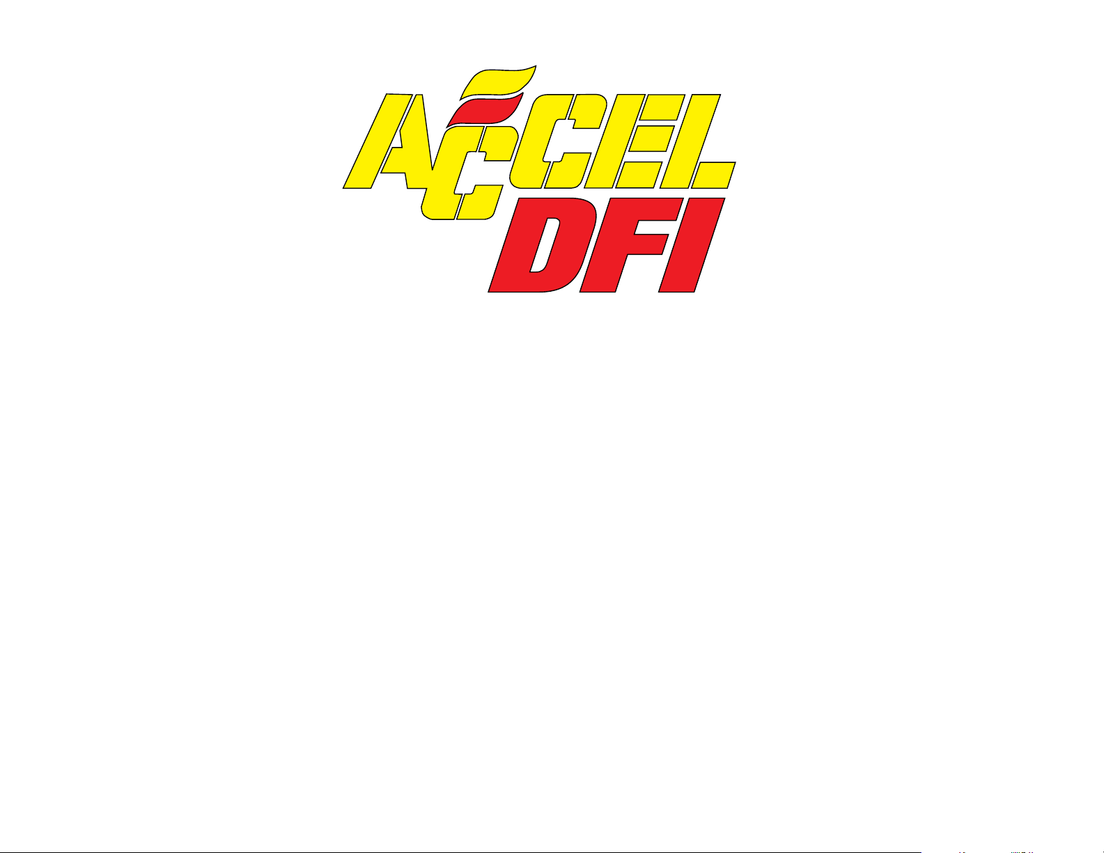
NON-COMPUTER CONTROLLED IGNITION
If you are using a non-computer controlled HEI (prior to
1985), points style distributor, etc. the Tach pick-up (1-pin
brown connector) must be used. Connect this lead to the
negative side of your coil. If the brown connector must be
removed for your application, be sure not
to remove the 39K
ohm resistor which is 3” from the existing connector.
NOTE: If you are using an aftermarket ignition
enhancer box (i.e.: ACCEL 300+, MALLORY
Hyfire) the MWH’s Tach pick-up connector
MUST be connected to the enhancer box’s Tach
output signal. It is also necessary to remove the
39K ohm resistor from the Tach pick-up wire. It is
3” from the end of the Tach pick-up lead. DO
NOT connect this lead to the negative side of
your coil if using an enhancer box, this can result
in ECM damage.
76
VI – CHOOSING YOUR DISTRIBUTOR
Page 6

ACCEL/DFIACCEL/DFI
ACCEL strongly urges the use of a good quality suppression
wire such as ACCEL 300+ or ACCEL RFI Suppression Wires.
We have encountered problems with various ignition wires
available on the market such as helically wound or solid core
not suppressing electrical noise. The use of these wires may
interfere with the operation of the ECM. Further, some high
energy aftermarket ignition units also produce electrical
fields which will interfere with the ECM’s operation. Use of
these units is strictly at the risk of the owner. Call ACCEL for
recommendations of ignition system compatibility.
The total advance you set the engine to will depend upon the
engine you have. Vacuum advance should be controlled with
the EGR port, which is located on the bottom of the throttle
body. ACCEL/DFI recommends a distributor with
adjustable vacuum advance. Once the total advance is set,
connect the vacuum advance canister. Adjust the vacuum
advance canister to maintain 20-26 degrees with a hot engine
at 800 RPM. Again, this is ACCEL’s recommendation,
depending upon the compression ratio and cam profile, you
may have to decrease timing to avoid detonation.
COMPUTER CONTROLLED IGNITION
If you are using a GM (F or Y body) computer controlled HEI
distributor the MWH’s four pin male black connector must
be used. When using a Y body HEI , the four pin between the
HEI and the MWH is compatible. However, if you are using
a F body HEI, the four pin connection on the MWH will not
plug directly into the distributor. In order to use a F body
HEI you will need additional wiring. ACCEL/DFI’s part
number 74170 will allow you to connect your distributor to
the MWH. You can also control timing with the ECM by
using a magnetic pick-up distributor or crank trigger. In
order to control timing with these ignition systems you
must get a modification done to your ECM (ACCEL/DFI
part number 74043-I), this modification will come with the
necessary additional wiring, but will not come with an
ignition enhancer box that is required. If you will need this
modification contact ACCEL/DFI for further instructions
and a shipping address.
In order to set the initial timing, the ignition bypass
connectors (white-one pin connector), incorporated into the
HEI leg of the main wiring harness, must be disconnected.
With the engine running hot at 800 RPM, manually adjust the
distributor to 6 degrees BTDC. Once adjusted, reconnect the
ignition bypass line. As soon as you connect the bypass line
the timing will then be controlled by the ECM. The spark
curve is preprogrammed into the ECM from ACCEL/DFI. It
has as initial timing of 20 degrees BTDC and a total timing of
34 degrees BTDC in by 3000 RPM. The timing curves, as well
as all other tables in the ECM, can be adjusted to better suit
your engines requirements using ACCEL/DFI’s calibration
software CALMAP.
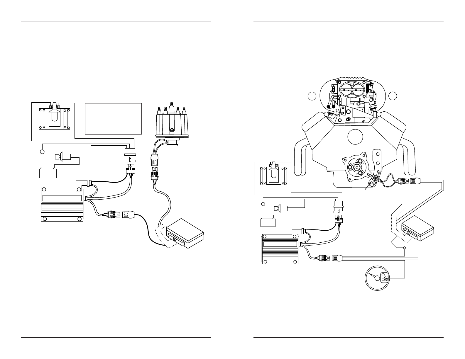
NOTE: If an aftermarket ignition enhancer box
is used (i.e.: ACCEL 300+, MALLORY Hyfire)
the Y body HEI can be wired as described by
the manufacturer. However, if you are using
an F body HEI or controlling timing with a
magnetic pick-up distributor or crank trigger
please reference figures E and F.
98
Page 7

ACCEL/DFIACCEL/DFI
ACCEL/DFI has two high pressure fuel pumps currently
available, an external mount fuel pump, part number 74701,
which can support up to 500 horsepower @ 45 PSI. The
second pump ACCEL/DFI offers (part number 74702) can
support up to 840 horsepower @ 45 PSI, this fuel pump can be
mounted in the fuel tank or on the frame rail. You can use
part number 74710 to mount this pump onto your frame rail.
Regardless of the fuel pump used, be sure to mount your fuel
pump near the tank at a point below the tank level, in a
protected area. System components must also be protected
and shielded from exhaust heat and engine compartment
heat as well as road damage.
Fuel Pump Wiring
The fuel pump requires a 12 volt source. If your vehicle was
an EFI vehicle originally, and already has a fuel pump
installed, you still MUST connect the +12 VDC side of the
fuel pump to the ACCEL/DFI main harness (red wire with
white tracer). The +12 VDC will come from fuel pump relay
via the red wire with white tracer in the main harness. The
fuel pump relay is already an integral part of the main
harness and is controlled by the ECM, therefore no wiring is
necessary for the relay. A pump will draw between 4 and 8
amps of current depending on size and fuel system pressure,
so 14 gauge wire should be used from the pump to the red
wire with white tracer. Also be sure to solder the connection
between these two wires. The ground for the fuel pump can
be at any clean, paint-free point on the chassis to the negative
(-) terminal of the fuel pump. Make sure that wiring between
the fuel pump and the engine compartment does not hang
below the vehicle, interfering with rotating parts or become
exposed to excess heat.
Mechanical Pump Removal
If your engine was carbureted, be sure to either cap off the fittings on your mechanical pump or remove the pump and
cover the opening with a block off plate.
High Pressure Fuel Filter Mounting
Locate the high pressure fuel filter at the outlet of the high
pressure fuel pump on the frame rail. It is recommended to
place a filter between the fuel tank outlet and the pump inlet
if the pickup tube in the tank does not have a filter. Failure to
do so can result in fuel pump damage. ACCEL/DFI high
pressure fuel filters, part number 74720, requires 3/8”
Saginaw fittings. If your fuel line does not have these fittings
you can use part number 74721, these adapter fittings will fit
the 74720 filter and allow you to use a 6AN fitting.
Routing High Pressure Fuel Hose
At this point the high pressure circuit of the fuel system can
be plumbed (refer to figure G, Page 28). If the existing fuel
supply line cannot sustain 150 PSI pressure (DFI recommends a fuel line rated to at least 330 PSI), then it must be
replaced with high pressure fuel line/tubing. Remember,
with a carburetor, your fuel system operated at about 6 PSI.
However, with fuel injection, the system operates around 50
PSI of fuel pressure. Never take any chances. If in doubt,
replace the hose. You will need a minimum of 3/8” ID supply line and 5/16” ID return.
Dual Fuel Tanks
It is important to note that for vehicles with either two fuel
tanks and/or class “A” RV’s it is highly recommended that a
boost pump be installed in each tank and feed through a
multi port switching valve, especially when operating in hot
1110
VII – FUEL PUMP MOUNTING AND
HIGH PRESSURE LINE INSTALLATION
Page 8

ACCEL/DFIACCEL/DFI
climates. Boost pumps used on such vehicles as a 1985 Ford
F-250 5.0L EFI will work well for this type of application. The
switching valve from a 1984 Ford 6.9L Diesel or a 1986
Chevrolet C-10 (305 CID) will work well in dual tank applications. Dual tank equipped vehicles must be plumbed to
return excess fuel to the tank which is supplying fuel to the
EFI system to avoid tank overflow problems. The remotely
activated dual tank three way valves described above will
work well in these applications.
A NOTE TO THE INSTALLER
There seems to be a misunderstanding with some people
that a fuel pump “produces pressure”. This is wrong. What
actually happens is the pump produces fuel flow at a given
system pressure which is dictated by the pressure regulator.
The pressure regulator has a spring which is preset to
provide a certain system pressure, i.e. 45 PSI. The regulator
opens as the pressure in the fuel line increases due to the flow
of fuel provided by the pump.
As the pressure drops, due to bypassing of fuel to the tank,
the regulator closes at a pressure of 45 PSI (this pressure is
variable on adjustable regulators). This process will begin
again as pressure raises. Therefore, the pressure regulator is
a dynamic modulating device which is always trying to seek
its preset pressure.
Sending Unit Modifications
To install a return fuel line in your tank, remove the sender
assembly from the fuel tank and drill a 5/16” hole through
the top of the flange. Be sure to give yourself enough room to
weld the tube into place; welding procedures are discussed
later in this section. ACCEL/DFI Jumper Line Kit, Part
Number 74731, will supply you with the this line as well
13
with other lines that you may need. Pre-bend a piece of
5/16” fuel line so that the in tank portion end is 2” from the
bottom of the tank and away from the existing outlet tubes
(see figure H). Ensure that the installation of this line does
not interfere with any other components on the tank unit.
Clean the unit with soap and water prior to the next step.
Seal and secure the return line to the flange by welding or
brazing with low heat so that flange warpage does not occur.
Also make sure that applied heat does not damage the sending unit wires or wire seals. Clean the welded area and check
for cracks or holes in the flange, tubes or welded area.
Check the condition of the filter sock on the pick-up tube. If
the sock is torn or contaminated, replace it. Again, if you are
not using a filter sock in your application then install a filter
between the fuel tank supply line and the inlet side of your
fuel pump.
Return Fuel Line Installation
If your vehicle was originally equipped with a carburetor,
you MUST run a 5/16” diameter or larger return line from
the engine (fuel pressure regulator) to the fuel tank. Some
vehicles with carburetors came with 1/4” diameter return
lines. This line is too small in I.D. and will create an
unacceptable amount of back pressure in the fuel line, thus
causing a rich condition. Using good judgment install a fuel
line from the pressure regulator outlet to the fuel tank with
restriction free bends in protected areas (refer to figure H).
The fitting at the pressure regulator is a #5 AN fitting and
ACCEL/DFI recommends a #5 AN to 5/16” Aeroquip stainless fuel line connector to connect the 5/16” return fuel line.
ACCEL/DFI recommends using a good fuel line for supply
and return line plumbing, such as a double braided stainless
steel AQP by Aeroquip.
12
Page 9

ACCEL/DFIACCEL/DFI
The ACCEL/DFI system comes with an oxygen sensor and a
M18 X 1.5 hex nut. This nut is to be welded to the collector
(preferably away from the passenger side) of the exhaust
header, if you are not using headers, please refer to figure I.
You will want to mount this closest to the header flange (or
exhaust manifold) without interfering with exhaust
connecting flange.
Prior to mounting the nut, drill a perpendicular 5/8”
diameter hole in the exhaust pipe or header collector.
If using a stock TPI or 58mm throttle body, use ACCEL
Powerfilter part number 74550. If you are using a 750 CFM or
1200 CFM throttle body, these throttle bodies have a 5-1/8”
filter surface, therefore any carburetor style air cleaner
will work.
At this point all the electrical connections should be made
between the sensors, computer, and optional equipment.
Keep in mind that you will have at least one extra connector
that will not be used on the main wiring harness. Now
connect the positive terminal to the positive side of the
battery, and the ground wires (see figure B or figure C
depending on application) to the negative battery terminal.
Prior to adjusting the TPS the throttle blades need to be
initially set. This can be done by backing the throttle stop
screw out so the throttle blades bottom out in the bore.
ACCEL/DFI has found a good starting position on a stock
throttle body to be four (4) turns in, once the screw makes
contact with the throttle blade tang. Again, this is just a
starting point and every application will vary. Next loosen
the screws that secure the TPS.
With the motor running, measure the voltage across pins
A & B of the TPS with a volt meter. Rotate the sensor until
+0.5 volts is shown. This can also be done using CALMAP,
consult your CALMAP users guide.
1514
VIII – MOUNTING THE OXYGEN SENSOR
IX – AIR CLEANER ASSEMBLY
X – TPS ADJUSTMENT
Page 10

ACCEL/DFIACCEL/DFI
Turn the ignition key to the run position. Do not crank yet.
The fuel pump should run for two seconds, then shut off.
Now turn the ignition key off. Repeat this procedure of
turning the key on and off four (4) times. Again, listening
carefully for the fuel pump. This is needed to prime the fuel
delivery system. The best way to check is to connect a fuel
pressure gauge to the shroeder valve on the passenger side
fuel rail. ACCEL/DFI offers gauges for certain applications,
check your application with one of our dealers. Now check
for fuel leaks along the entire vehicle length. Crank the
engine. After the engine starts the engine should fast idle and
the speed will decrease as the coolant temperature heats up.
If the engine does not start after ten seconds of cranking,
listen or feel for the injectors opening and closing, insure the
following:
a) All electrical and mechanical connections are made
securely.
b) There are no fuel leaks. The cold start valve block off kit
was properly installed and tightened (if this applies to
your application).
c) The fuel feed line is pressurized with fuel. The most
common problem is the fuel pump is wired backward.
On the ACCEL pumps, the (+) and (-) designations are
casted in the pump adjacent to the terminals. If the
ACCEL 74702 pump is wired backward, it will run
backward.
d) Insure that the engine timing is properly set. After the
vehicle starts, check for fuel leaks along the entire
length of the vehicle.
User Interface Module (UIM, part number 74500)
This option allows the driver to change the three
dimensional fuel table while the engine is running. The UIM
contains two potentiometers for increasing or decreasing the
amount of fuel supplied to the engine during idle and WOT.
The idle potentiometer provides the user with the ability to
increase or decrease the amount of fuel at idle and part
throttle fuel by 10%. The WOT potentiometer comes into
play only when the throttle is fully opened. The percent
increase and decrease is 25%. The UIM does not change the
amount of fuel delivered during cranking.
The UIM must remain connected to the main wiring harness
after adjustments are made to the ECM. If it is disconnected,
the ECM will automatically default back to its preset values.
If your engine requires a somewhat different calibration than
is noted on the ECM, or you are calibrating a unique engine
combination, use the ACCEL/DFI Serial Communications
Interface option, CALMAP (Part Number 74990-S with 5ft
cable, 74990-L with 25ft cable). This software will allow you
to customize the Fuel and Timing curves as well as all other
parameters in the ECM.
F-BODY HEI DISTRIBUTOR KIT
(PART NUMBER 74170)
This kit will allow you to use a F-body HEI to control timing
with an ACCEL/DFI system. The kit consists of a jumper
harness that goes between the MWH and the distributor as
well as one that goes between the distributor and your coil.
In addition to these there is also a connector that will go
between your coil and a power source.
1716
XII – OPTIONAL ITEMSXI – STARTING THE VEHICLE
Page 11

ACCEL/DFIACCEL/DFI
KNOCK SENSOR HARNESS KIT
(PART NUMBERS 74174- S.B. CHEVY 74175 B.B. CHEVY)
The knock sensor harness kit allows the end user to
incorporate a GM knock sensor to detect detonation and
automatically retard the spark timing. The kit comes with a
harness which interfaces between the GM ESC Module, GM
knock sensor and ECM. Since these sensor are calibrated for
Chevrolet engines only they can only be used on Chevrolet
engines.
FAN CONTROL KIT (PART NUMBER 74171)
This kit includes a harness with integral relay that interfaces
between the ECM and the fan. This kit allows you to turn on
an electric fan at a given engine temperature via CALMAP.
This kit does not include a fan.
TORQUE CONVERTOR LOCKUP KIT
(PART NUMBER 74172)
This kit includes a harness with integral relay that interfaces
between the ECM and 700R4 Converter Lockup connector.
This kit allows you to lockup and unlock the converter at a
prescribed speed (RPM), and throttle position (TPS) using
the CALMAP software. Be advised that if your 700R4 is in a
truck (or came out of a truck) that some additional wiring
and an extra relay will be required.
NITROUS CONTROL KIT
(PART NUMBERS LISTED BELOW)
S.B. Single Stage Part Number 74172
B.B. Single Stage Part Number 74182
S.B. Multi Stage Part Number 74183
B.B. Multi Stage Part Number 74181
This kit includes a harness with integral relay that interfaces
between the ECM and the nitrous solenoid. The kit
also comes with a toggle switch, nitrous plate (which
bolts between the plenum and the throttle body), and the
necessary lines and fittings. This kit enables you to control a
nitrous solenoid and at the same time controls spark timing
and fuel enrichment.
1918
Page 12

ACCEL/DFIACCEL/DFI
The following are some common problems we have encountered with various installations.
Injectors not firing (clicking) - the vehicle will not start:
• Usually due to a low battery. Voltage must be
above nine volts during cranking to activate
the ECM.
• Injector harness not connected to the main
wiring harness.
• Short in either pin P1-C7 or P1-C8. Check
continuity to battery positive and negative
wires with an OHM meter.
• Tach wires to positive side of coil instead of
negative.
• P1-D7 (long pink wire with female spade
connector) not receiving 12 volts during
cranking. Usually due to connecting this
wire to a voltage source that is disabled
during cranking.
Runs rich at idle:
• Vacuum line to fuel pressure regulator not
connected.
• MAP sensor vacuum line pinched.
• UIM idle knob turned all one way.
Runs rich all the time:
• Wrong injectors for the application.
• Return fuel line is too small/restricted.
• Calibration in the ECM is wrong for the
application.
Engine cranks a while before starting:
• +12V and ground terminals not connected
directly to battery.
• Fuel pump is not priming the fuel system.
If you are experiencing problems please contact your
ACCEL dealer or feel free to contact ACCEL’s technical
service line and talk to an ACCEL/DFI technical representative.
ACCEL’s technical phone number is: 1.216.398.8300 EXT: 500.
Written by Charlie Trombley
2120
XIII – TROUBLE SHOOTING GUIDE
Page 13

22
ACCEL/DFIACCEL/DFI
23
Figure A
3 PIN Green Connector
to MAP Sensor
5 PIN White
Connector to Main
Harness (Female)
+12V Switched
to Fuse Box
1 PIN Black
Connector to ESC
4 PIN Black Connector to
Computer Controlled HEI
2 PIN Grey Connector
to Air Temp. Sensor
2 PIN Black Connector to
Water Temp. Sensor
3 PIN Black Connector
to TPS Sensor
4 PIN Black Connector
to IAC Motor
Black/White Black
Black/Purple to Battery
Ground (-)
Red to Battery
Positive (+)
5 PIN Black
Connector to Injector
Harness (Male)
Grommet
Firewall
1 PIN Brown Connector
to Tachometer Pickup
for Non-Computer
Controlled HEI
3 PIN Black
Connector to
O2Sensor
Red/White to Fuel
Pump Positive (+)
Figure B
Bypass Wire
6 Pin Power
Tuner Connector
4 Pin Calmap
Connector
30 AMP Fuse
3 AMP Fuse
Page 14

ACCEL/DFIACCEL/DFI
2524
Black/White Black
Black/Purple to Battery
Ground (-)
Red/White to Fuel
pump Positive (+)
Pink Wire to 12V
Switched on Fuse Box
Pink Wire to 12V
Switched on LT1
Harness
5 PIN Round White
Connector to Main
Harness (Female)
2 PIN Black
Connector to Water
Temp Sensor
2 PIN Grey Connector
to Air Temp Sensor
4 PIN Connector to
Optispark Distributor
3 PIN Black Connector
to TPS Sensor
1 PIN Male Connector
for Tach Lead
2 PIN Grey & 2 PIN
Black Connectors
to Coil
1 PIN Male/Female
Connector to Coil (-)
3/8" Ring Terminal
to Ground
4 PIN Black
Connector to
Ignition Module
3 PIN Green
Connector to MAP
Sensor
5 PIN Black
Connector to Injector
Harness (Male)
Firewall
Grommet
3 PIN Black
Connector to O
2
Sensor
Red to Battery
Positive (+)
Figure C
3 AMP Fuse
30 AMP Fuse
MAP Sensor
TPS Sensor
IAC Motor
Main Wire Harness
H2O Sensor
1-5/8 Hole thru firewall
for grommet in main
harness - 2 places
Approx.
Location
Approx.
Location
Figure D
6 Pin Power
Tuner Connector
4 Pin Calmap
Connector
Page 15
ACCEL/DFIACCEL/DFI
27
Distributor
Coil
-+
ACCEL 300+
Key
Battery
Ground
ACCEL
DFI
Orange
(+)
Purple
(-)
Black
Figure E
MSD Purple = (-)
Orange = (+)
ACCEL Red = (-)
Green = (+)
Black = (-)
White = (+)
26
1
2
3
4
5
6
7
8
9
10
Coil
-
+
White
Black
Purple
Orange
ACCEL
DFI
ACCEL 300+
Crank Trigger
Key
Battery
Ground
Figure F
Change
P1-B1 to
P1-B7
Change
P1-B1 to
P1-B7
Wires
Not Used
White
Green
Page 16

ACCEL/DFIACCEL/DFI
29
6AN to 3/8"
Compression
3/8 Braided Line
ACCEL Part# 74710
Fuel Pump Bracket
ACCEL Fuel Pump
Part# 74702
6AN Braided Line
Fitting
ACCEL Part# 74721
3/8 Braided Line
3/8 Inlet on Fuel Rail
TPI Fuel Rail Fitting Package
ACCEL Part# 74730
3/8 SAG/GAN 5/16 SAG/GAN
ACCEL Part# 74720
E.F.I. Filter
5/16 Braided Line
6AN Braided Line
5/16 Return Line on Fuel
Pressure Regulator
6AN tp 5/16" Compression
5/16" Return
Line to Tank
To Fuel Tank
Figure G
28
5/16 Fuel Return Line Must Be
Added to Non-Fuel Injected
Vehicles. See Installation
Manual for Proper Installation
Braze Tube to Flange
making Sure Not to
Melt any Rubber or
Plastic Components
Existing Wire Harness
High Pressure Feed
Vapor Vent
Emissions/Canister
Top of Tank
Bottom of Tank
Return Line
2"
Figure H
Stock Exhaust Manifold Style
Header Style
Weld All Around
Figure I
3/8 Feed From
Fuel Line
5/16 SAG to 6AN
5/16 SAG to 6AN
NOTE: If using ACCEL Pump Part #74701, please contact ACCEL/DFI Technical Service for proper plumbing instruction.
Page 17

www.accel-ignition.com
Printed in U.S.A. 01/12
 Loading...