

Page 1
Page 2

Congratulations! You have purchased the ACCEL 3-STAGE REV-LIMITER.
This unit allows you to program three different rev-limits
and make use of two different RPM-activated switches.
These rev-limits and switches can be particularly useful to Drag Racers.
You must use your A
CCEL 3-STAGE REV-LIMITER
with one of the ACCEL+ ignition modules.
Use ACCEL 300+ RACE WIRE spark plug wires!
Solid-core spark plug wires emit RFI and EMI static,
which can disrupt On-board electronics.
Do not use your 3-STAGE REV-LIMITER
with more than 18 volts.
Your ACCEL 3-S
TAGE REV-LIMITER, like
any electronic component, is sensitive to heat.
Keep it away from temperatures greater than 150°F
(65°C).
Follow the installation instructions in this Owners Manual carefully.
ncorrect installation can damage the unit, your engine, and VOID YOUR WARRANTY
This unit cannot be returned to your
dealer for testing or for warranty.
It must be returned to
:
MR. GASKET PRODUCT REPAIR
8700 BROOKPARK ROAD
CLEVELAND, OH 44129
216-398-8300 Ext-310
Your warranty card must be on record at
ACCEL
to insure warranty processing.
(See your warranty card for details.)
.
This package provides everything
you will need to install your
ACCEL 3-STAGE REV-LIMITER
Wire lengths provided are enough for almost all vehicles.
If you must splice additional wire use 16 gauge wire, or larger.
Page 3

THE
3-STAGE REV-LIMITER - AN OVERVIEW
our new ACCEL 3-S
TAGE
REV -LIMITER is a computer module. It is meant to be installed
etween the ignition trigger device (distributor pickup, crank trigger, etc.) and an A
nition module. It controls the signals that tells your A
n addition to the trigger input, your A
CCEL
CCEL+ ignition when to fire.
-Stage Rev-limiter uses two additional
puts to select rev-limit values. Both of
ese inputs may be connected to any type
f switch to activate selected rev-limits.
ou can then adjust their rev-limiting
nges with the key pad.
CCEL 3-Stage Rev-limiter can also
our A
ctuate, through two 2-pin connectors, two
xternal devices (Typically a N
2O solenoid and an ACCEL Shift Light). Both of these two
evices are actuated by setting their engine RPM values on the key pad.
MODES OF OPERATION
Your new ACCEL 3-Stage Rev-limiter has three different modes of operation.
1. Programming The Programming and Control modes overlap in the sense
2. Control
value you are programming and the ‘programming dot’ blinks in the upper left corner of
of the display. In Control mode the display shows current RPM.
3. Diagnostics – See Pg. 11.
that the engine’s rev-limit control is still performed while in the
Programming Mode. In Programming Mode the LED’s display the
CCEL+
PRECAUTIONS AND WARNINGS
The ACCEL 3-Stage Rev-limiter can only be used with ACCEL ignition modules.
We strongly suggest that you deactivate any N
initial programming, to prevent accidental activation.
The A
CCEL 3-Stage Rev-limiter will cause a small, fixed timing retard in the trigger.
This is due to computational delay. Engine ignition timing must be checked and
re-adjusted, to account for this delay, after your 3-Stage Rev-limiter is installed.
Use caution when selecting and changing values.
This flexible product makes it easy to select values that could damage your engine.
Start with safe values and carefully evaluate their effect. Make small changes.
2O system during installation and
Page 4
CONNECTING T
TO AN
HE
ACCEL 3-STAGE REV-LIMITER
A
CCEL IGNITION SYSTEM
he ACCEL 3-Stage Rev-limiter uses special signals to communicate with your ignition
module, and your 3-Stage Rev-limiter can only be used with an A
or your rev-limiter to communicate with your ignition module
gnition module, must be re-set
UP.
CCEL ignition module.
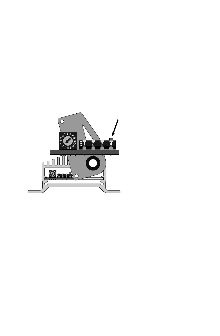
DIP-Switch-4, inside the
• Open the ignition module’s cover plate (the one with the wires coming through it).
Unscrew the three screws and swivel it out of the way to reveal the
• Using a small tool (A pencil is good) gently push
This A
CCEL 300+ ignition box has been
DIP-Switch-4 up.
DIP-Switches.
set to rev-limit an 8-cylinder
engine at 5,000 RPM.
DIP-Switch-4
The owner has
installed an A
3-Stage Rev-limiter,
and has also set
DIP-Switch-4 up.
CCEL
Your A
CCEL ignition system’s internal
DIP-Switches are harder to access
than your rev-limiter’s buttons.
Set the ignition box’s rev-limit to the
highest value you ever expect to reach.
Your rev-limiter cannot override the
ignition’s designated rev-limit.
• When you have adjusted DIP-Switch-4, close the cover plate and
retighten all three screws.
IMPORTANT POINTS TO REMEMBER
he rev-limit set inside your ACCEL ignition module is the engine’s ultimate rev-limit.
o outside control module will ever be able to override it. When setting
-Stage Rev-limiter it is a good idea to set it a little lower than the ignition module’s limit.
his allows you to program your A
hile using the A
you remove your A
CCEL ignition module’s
CCEL ignition module’s rev-limiter as a safety.
CCEL 3-Stage Rev-limiter. remember to re-set DIP-Switch-4 inside the
CCEL 3-Stage Rev-limiter for its highest performance,
• When connected to any control module, the ignition module’s DIP-Switch-4 must be UP.
• When not connected to a control module the ignition will not start with
PEAK RPM on your
DIP-Switch-4 UP
Page 5

After you have completed the wiring (according to diagrams detailed later in this
ocument) you must do some basic configuration of your ACCEL 3-Stage Rev-limiter.
SELECTING THE
N
UMBER OF CYLINDERS
1. With the unit powered off – press and hold
down the SAVE and SHIFT LIGHT buttons.
2. While holding those buttons down, apply power to the module.
The module will now display the (factory default) number
stored that represents the number of cylinders in an engine.
3. Use the ⇑and ⇓keys to select the number of cylinders for your engine.
4. When finished, press SAVE to store this new information and
put the module back into Control Mode operation.
Make this selection only once per installation.
When you do not make this selection your
3-STAGE REV-LIMITER uses the factory default.
SETTING REASONABLE REV-LIMITS
You should now set some reasonable values for your various rev-limits.
Enter Programming Mode by pressing the key for the function you wish to modify.
Exit Programming Mode by pressing that same key again.
i.e. Press
The display will show the current value and a dot will flash in the upper left.
Use the ⇑and ⇓keys to adjust the value displayed in 100 RPM increments.
When finished press the
The dot will stop flashing and the current engine speed will be displayed.
Do the same for all rev-limits and RPM-activated switches.
t is not necessary to exit Programming Mode to select a new function,
simply press the next value’s key.
After you have finished press SAVE to store all newly set values.
PEAK
to select your maximum engine speed.
RPM
PEAK
RPM
key again.
THE
SAVE BUTTON
Pressing the SAVE button tells the REV-LIMITER to store all of the values that have
been adjusted. They will be remembered, until they have been re-programmed and
over-written with the SAVE button. Turning off the unit does not erase values that
you have stored with the SAVE button.
You can adjust, and test, different settings, without storing values, by turning your
REV-LIMITER off, without pressing SAVE. The unit remembers all of the last values
stored with the SAVE button, and restores them the next time it is powered on.
CAUTION: It may take a few seconds for the module to save new values.
Be sure the display shows the engine RPM (default display) before turning the
module off. Powering off during a SAVE may cause you to lose stored values.
Page 6

Page 7

Page 8

CONNECTING THE
WIRING HARNESS
THE SQUARE, 4-PIN, FEMALE CONNECTOR
outputs directly to your ignition system.
When correctly installed, this connector
is a simple plug-in.
HE FLAT, 4-PIN CONNECTOR
attery’s positive pole (+12
RED wire is attached, through the ignition switch, to the
’s
VDC).
he battery’s negative pole is grounded,
nd this connector’s
BLACK wire must also
e attached to a good negative ground,
referably the Ground Strap.
DARK GREEN & W
he
HITE wire connects to
he Burn Out switch. When the Burn Out
witch is set
(ON) the 3-Stage Rev-limiter
ev-limits the engine at the value stored
BURN RPM.
or
DARK BLUE & WHITE wire is spliced to the wire connecting the Staging switch to
he
he Trans Brake, or the Line Lock solenoid. When this switch is released your engine is
ree to rev up to the value set for
PEAK RPM.
THE SHIFT LIGHT CONNECTOR is one of the
two 2-pin connectors. Its
VDC
provides +12
. Its BLACK & PINK wire is
RED & WHITE wire
switched to ground when the engine reaches
the speed programmed in S
HIFT LIGHT.
THE
N2O SOLENOID CONNECTOR
2-pin connector. Its
VDC. Its BROWN wire is also switched, to
+12
PINK wire also provides
is the other
ground when the engine reaches the speed
programmed in by the
N2O SWITCH.
Page 9

WIRING THE TACHOMETER
he LIGHT GREEN wire outputs, from your ACCEL ignition, to the Tachometer through your
ev-limiter. Some older tachs may need a resistor, wired to
POWER, to function correctly.
he Rev-limiter itself, when not being programmed, functions as a digital tachometer.
WIRING THE
TRIGGER
he ACCEL 3-STAGE REV-LIMITER accepts any and all kinds of trigger, except distributor-less.
s digital, micro-processor controlled, rev-limiter will be as sensitive as your trigger. We
ecommend the
ead through the square male connector’s
ACCEL Billetech Distributor or ACCEL Crank Trigger . Triggering inputs are
WHITE wire, or the PURPLE and ORANGE wires.
Your ACCEL ignition system should already have this connector in place.
he WHITE wire’s input is in the form of
Square Wave. It gets this input from
:
• All points ignitions
• Most fuel injections
• Some
PURPLE and ORANGE wires get their
he
HEI modules
nputs from only magnetic pickup or
rank-triggered systems
PURPLE wire is a positive (+) input
he
ORANGE is a negative (–) input.
nd the
(See chart for various connections.)
your system uses the WHITE wire you
P
ust isolate and insulate the
URPLE
nd ORANGE wires. If your system uses
PURPLE and ORANGE wires you must
he
W
olate and insulate the
* Older A
CCEL Crank triggers may connect WHITE to PURPLE and BLACK to ORANGE.
HITE wire.
TAGING WITH A
S
STANDARD TRANSMISSION
ars with standard transmissions cannot Stage with a Trans Brake or Line-lock. One
olution to this problem could be – Put a switch
When the clutch is released the Rev-limiter can rev up to the designated
(DK BLUE & WHITE) on the clutch pedal.
PEAK RPM Value.
you do install a clutch pedal switch remember that if you power shift with the clutch,
PM will be limited to the value you have set for STAGE RPM.
Page 10

CONNECTING S
OLENOIDS IN PARALLEL
Both the 2-pin, female output connectors are switched to Ground inside
he Rev-limiter, and both connectors supply enough power to drive
multiple solenoids. Two solenoids in parallel is
ommon, but various manufacturer’s solenoids,
may have different energy requirements.
ACCEL 3-STAGE REV-LIMITER can drive up to three HURST solenoids (Roll Control solenoid
he
alve – Part# H566 7550) wired, in parallel, to either of these two 2-pin outputs.
THE ACCEL
Your ACCEL 3-STAGE
3-STAGE REV-LIMITER AND
REV-LIMITER requires an ACCEL
ENGINE CONTROLS
+ ignition.
• It cannot be installed on a Distributor-less engine.
• It cannot be installed on a third party’s Multi-strike CD ignition.
You can connect any engine controller to your A
ACCEL 3-STAGE REV-LIMITER, that controller must input to the Rev-limiter’s square,
n
male connector first, connecting to the A
The A
CCEL Rev-limiter inputs its trigger (4-pin, square, male connector) from:
CCEL+ ignition through the Rev-limiter.
CCEL+ ignition, but if you are also using
•Directly from the triggering device through the ORANGE and PURPLE wires.
(IE. Crank or Mag Trigger, Billetech Distributor)
•Either an ACCEL Timing Computer or an ACCEL Timing Retard Module.
(Not both.)
•A third party engine controller through the WHITE wire.
(Assemble a wiring harness with the enclosed connector.)
THE LAST WORD IN REV-LIMITING
Your ACCEL ignition system has the final authority over your peak rev-limit. Neither your
-Stage Rev-limiter, A
ngine’s RPM to exceed the rev-limit you have set inside your A
CCEL Timing Computer, or any other connected device, can cause your
CCEL ignition system.
Page 11

LED’s do The Rev-limiter is not getting power.
not display Check the 4-pin, flat connector’s
Red and Black wires. See Pg-6.
LED’s display The Rev-limiter is not getting a Trigger.
000 Check the 4-pin, square connector, and check the color of the wires.
See the wiring diagram on Pg-6 and the triggering chart on Pg-9.
Status light Your ignition is not firing or it has unplugged from the Rev-limiter.
is Dim Check the battery and all three 4-pin connectors and all their wires.
If the connectors and the battery are both OK, pull out a spark plug
and lean it against the block. It should spark as you crank the engine.
Status light The ignition is not plugged into the Rev-limiter or not working.
is Off Check 4-pin connectors, battery, and sparking.
Incorrect Tach Wrong cylinder selection (4, 6, or 8 cylinders).
reading This may also cause rev-limiting at the wrong
RPM. See Pg-5.
No Burn or Check the Line Lock and Trans Brake wiring and their switches.
Stage Rev-limit See Pg-6.
atching potential If there is a problem actuating Nitrous, you may not discover it until
problems with it is too late. Incorrect Nitrous actuation can destroy your engine!
Nitrous One way to find a potential installation or actuation problem, before
it can cause damage
: unplug the Nitrous system and make one run
with your Shift Light plugged into the Nitrous connector. See Pg-8.
DIAGNOSTIC MODE
(Please read this whole section before you enter Diagnostic Mode)
he ACCEL 3-Stage Rev-limiter has features that test functions through your key pad.
iagnostic Mode does not perform any Control Mode engine functions.
you enter Diagnostic Mode with the engine running, your engine will stall.
ISPLAY, PROCESSOR and MEMORY test
Enter Diagnostic Mode by simultaneously pressing and releasing three keys:
BURN
RPM, STAGE RPM,
and PEAK
. The display will show
RPM
00000.
About every two seconds the display will increment: 11100, 22200, up to 99900.
The ‘degree dot’ will appear with the odd numbered (
EY PAD test
When
99900
appears the ‘programming dot’will start flashing. From now on you must
11100, 33300) displays.
press the proper key within eight seconds or the module will return to Control Mode.
Keys must be pressed in order:
DISPLAY PRESS
99900 BURN
11100 STAGE RPM
22200 P
33300
44400
55500 SHIFT LIGHT
66600 SAVE
77700 N
RPM
EAK RPM
(UP A
⇑
(DOWN Arrow)
⇓
2O SWITCH
rrow)
After each key is pressed the display will update.
It starts at
11100 and increments to 77700 as
each key is pressed, in order. If the proper key
is not pressed within eight seconds Diagnostic
Mode ends, returning you to Control Mode.
If you press the correct key and the display does
not update (and the unit exits Diagnostics), the
test has found a key pad failure.
When the last key (
N2O SWITCH) is pressed and
released the unit returns to Control Mode.
Page 12

An RPM-Activated switch that turns on an external ACCEL SHIFT LIGHT.
Press the S
The Red
The Black
HIFT
&
White wire provides +12 VDC.
&
Pink wire is switched to Ground.
button. Adjust the setting with the ⇓or ⇑ buttons.
LIGHT
Another
RPM-Activated switch. This one actuates an external solenoid
normally used to add Nitrous Oxide into the Air/Fuel mixture.
Press the N
The Pink wire provides +12
2O button. Adjust the setting with the ⇓ or ⇑ buttons.
VDC, Brown wire is switched to Ground.
Selects the BURN RPM Rev-limit.
Is activated by a switch (Dark Green
B
URN
RPM
Press the
Selects the S
TAGE RPM. It is activated by switch (Dark Blue & White
button. Adjust the setting with the ⇓ or ⇑ buttons.
&
White wire) on the dashboard.
wire) on the shifter, which typically activates the Line Lock or Trans
Brake solenoid. Rev the engine up to S
is released the engine is free to rev up to P
Press the S
Sets the maximum
TAGE
RPM button. Adjust the setting with the ⇓or ⇑ buttons
RPM that you will allow your engine to reach.
TAGE RPM. When the switch
EAK
RPM.
Press the Peak RPM button. Adjust the setting with the ⇓ or ⇑ buttons
(This setting will not override the rev-limit set inside your ACCEL ignition box!).
INSTALLATION
CHECKLIST
Disconnect the battery’s negative (ground) connections.
Disconnect any N
Install the your A
Set the A
2O connections.
CCEL ignition module and set its DIP-Switches. (Pg. 4)
CCEL ignition module’s DIP-Switch-4 up!
Either set the ignition module’s rev-limit higher than the Peak RPM you will
program into the 3-Stage Rev-limiter or disable the ignition module’s rev-limit.
Install and connect the flat, 4-pin connector. (Pgs. 8, 9,
& Wiring Diagram)
BURN RPM switch
STAGE
RPM
switch.
Connect the trigger input (square male connector). (Pg. 9)
Connect an A
CCEL Shift Light (one of the 2-pin male connectors). (Pg. 8)
Reconnect the battery.
Set the proper number of cylinders. (Pg. 5)
Program reasonable values for
Program reasonable values for RPM related activities: N
Save these initial values into memory with the
BURN RPM, STAGE RPM and PEAK RPM. (Pg. 5)
2O, Shift Light.
SAVE button. (Pg. 5)
Adjust and verify engine timing
N
2O activation verified with Shift Light, then connected to its solenoid.
Fine tune any values that need adjustment and save the new values.
Page 13

A
DRAG RACE COIL
Part # 140010
CCEL
ACCEL 3-ST AGE REV-LIMITER
COMPATIBILITY
CHART
CCEL SUPER COIL
A
Part # 140009
CEL TIMING R
an ACCEL T
ETARD MODULE (Part # – 49355
IMING COMPUTER (Part # – 49340)
Either one inputs to your
ACCEL+ ignition through your
ACCEL 3-STAGE
REV-LIMITER.
Any of the A
ignition systems, in
this case an
A
CCEL 300+.
)
.
CCEL+
The ACCEL 3 STAGE
REV -
LIMITER
accepts inputs
from any distributor, crank
trigger, fuel injection,
ACCEL
control module.
It inputs from switches and solenoids
that control burn-out and
staging RPM,
2
and N
O.
The ACCEL 3 STAGE
LIMITER inputs its signals
directly to your A
ignition.
Any additional control
modules must input to the
ignition through your Rev-limiter
OR
REV-
CCEL+
.
ILLETECH
B
DISTRIBUTOR
Fuel Injection
and/or
Nitrous system.
ACCEL CRANK
TRIGGER
 Loading...