

Mallory Ignition 21715 User Manual

WORK SAFELY!
Installation of these traction bars
requires working underneath vehicle and should be
performed one side at a time. USE EXTREME CARE
AND CAUTION WHEN WORKING UNDERNEATH
VEHICLE. Never get near or under vehicle until you
are confident that it is safely supported and will not
move or fall from its raised position.
DO NOT USE A BUMPER JACK.
PREPARATION FOR INSTALLATION
1. Place vehicle on a solid level surface to ensure safe
installation
2. Place wheel blocks in front of and behind both front
wheels to prevent movement in either direction.
3. Raise rear of vehicle and support axle housing using
approved automotive support stands having adequate
load capacity. Place support stands under axle tubes
in an area to allow adequate clearance for installation
of traction bars. DO NOT place support stand directly
under spring. DO NOT allow axle housing to hang
freely. Note: Depending on ground clearance under
vehicle, it may be possible that installation can be
done without raising vehicle.
CAUTION:
DO NOT BEGIN THIS INSTALLATION UNTIL
YOU ARE CONFIDENT THAT VEHICLE IS SECURE AND
SAFELY SUPPORTED.
TRACTION BAR INSTALLATION
1. Attach snubber to front hole of each traction bar
using Ny-lok nut supplied and tighten securely.
2. Place traction bar under spring and position bar so
that rear mount bracket is in back of axle housing
and front mount bracket is in front of axle housing
with snubber located under front spring eye.
3. Attach the traction bar to the spring with the
mounting clamp plates and hardware provided
(mounting clamp plates go on top of spring).
Do not tighten completely.
4. Adjust front to rear location of bar as necessary to
allow adequate clearance and no interference
around the traction bar (U-bolts, parking brake cable,
shock mounts, brake lines etc.).
5. Tighten mounting clamp bolts just enough to
eliminate any clearance between traction bar
brackets and leaf spring. Do not tighten completely.
6. Measure distance between top of snubber and front
spring eye. We recommend an 1/8" clearance gap as
a good starting point. The gap can be adjusted to suit
your driving requirements with the various shims
that are included in the hardware kit. Add shims
under the spring at the rear mounting bracket to
decrease the gap, or add shims under the spring at
the front mounting bracket to increase the gap (see
recommended adjustments).
7. Tighten front and rear clamps to 45-50 lbs. ft. torque.
8. Repeat the above procedure (steps 1 - 7) on other
side of vehicle.
9. Lower vehicle onto a solid level surface. Measure
distance (clearance gap) between top of snubber and
spring. On competition vehicles it is recommended to
eliminate the gap. On street/strip vehicles, a 1/2" gap
on the right side bar and a 3/8" gap on the left side
bar will allow for a much better ride. Use shims
provided to adjust the clearance gap as necessary.
NOTE:
When properly installed and vehicle on level
surface, snubber end of traction bar must angle up or
be parallel with chassis. Under no circumstances should
vehicle be operated with snubber end angled down.
Important:
Do not attempt to level the vehicle with the
snubbers as this will cause radical preloading and
torque steer problems.
RECOMMENDED ADJUSTMENTS
Your rear suspension can be fine tuned for street or
strip by adjusting the traction bars. For a better ride, the
LAKEWOOD TRACTION BARS
#21715
INSTALLATION INSTRUCTIONS
Fits 1986-2000 Ford F-150 Pick-up Trucks and
1973-1987 Chevy/GMC 1/2 Ton Pick-up Trucks with 2 Wheel Drive
Lakewood Industries is a Mr. Gasket Performance Group Company.
©2001
snubber clearance gap should be increased. For a firm
competition ride, the snubber clearance gap can be
decreased. If vehicle torque steers (pulls to right or left)
under acceleration due to traction bars, the
snubber clearance gap can be adjusted to eliminate this
problem.
To correct unequal traction, try the following:
a) Be sure that both tire pressures are equal.
b) If vehicle torque steers to the right under
acceleration, decrease the gap on the right
side bar.
c) If vehicle torque steers to the left under
acceleration, decrease the gap on the left
side bar.
REPLACEMENT PARTS
Urethane Snubbers (2/set) . . . . . . . .#20700
Rubber Snubbers (2/set) . . . . . . . .#20530
TECHNICAL SERVICE
A highly trained technical service department is
maintained by Lakewood Industries to answer your
technical questions, provide additional product
information and offer various recommendations. See
your local retailer of Lakewood products for specific
prices. Technical service calls, correspondence and
warranty questions should be directed to the
following address:
Lakewood Industries
10601 Memphis Ave. #12
Cleveland, Ohio 44144
Phone 216-688-8300 ext. 500
8:30 A.M.-12:00 P.M., 1:00 P.M.-5:00 P.M. EST
www.mrgasket.com
RETAIN THIS INSTRUCTION SHEET
FOR FUTURE REFERENCE.
P/N 97144059
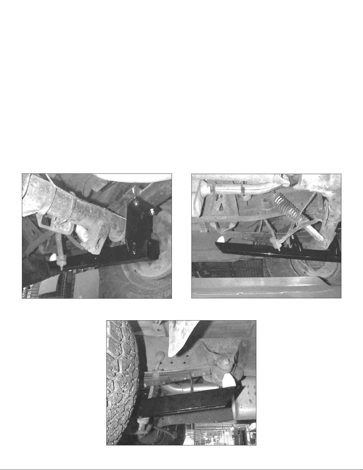
Rear bracket with mounting clamp on top of spring.
Position bar to allow adequate clearance around
brake lines, parking brake cable, etc.
Locate snubber under front spring eye.
 Loading...