

Page 1
LAKEWOOD “TRACTION . . . ACTION” LIFT BARS
INSTALLATION INSTRUCTIONS
Part #21700
Fits 1982-2001 Camaro/Firebird
Features:
• Legal for NHRA Stock Eliminator Classes
• Completely bolt-on. No welding required
• “Adjustable” load control strut link to allow
right or left suspension pre-load for fine tuning
the chassis under various track conditions
• Polyurethane bushings for positive suspension
control and stability
IMPORTANT!
Read this instruction sheet completely
so that you thoroughly understand it
and can become familiar with the procedure
before attempting installation.
WORK SAFELY!
Installation of these traction bars requires
working underneath vehicle.
USE EXTREME CARE AND CAUTION WHEN
WORKING UNDERNEATH VEHICLE.
Never get near or under vehicle until you are
confident that it is safely supported and will
not move or fall from its raised position.
DO NOT USE A BUMPER JACK.
PREPARATION FOR INSTALLATION
1. Place vehicle on a solid level surface to ensure
safe installation.
2. Place wheel blocks in front of and behind
both front wheels to prevent movement in
either direction.
2. Apply lubricant (supplied) to polyurethane
bushings and steel sleeves, then install into
eyelet ends as shown.
3. Assemble load control strut links using ball rod
ends and hex jam nuts supplied.
Note:
There are right and left hand thread ball rod
ends, use the correct ball rod end and hex
jam nut on each end of the strut link.
TRACTION BAR INSTALLATION
Note:
We recommend working on only one side
at a time. The traction bars should be
installed with the load control strut bracket
facing down and positioned toward the
front chassis mount.
CAUTION:
DO NOT BEGIN THIS INSTALLATION UNTIL
YOU ARE CONFIDENT THAT VEHICLE IS
SECURE AND SAFELY SUPPORTED!
1. Remove both rear wheels.
2. Apply penetrating oil or rust release lubricant
to front and rear mounting bolts of lower
control arms, lower shock absorber studs and
stabilizer bar hardware.
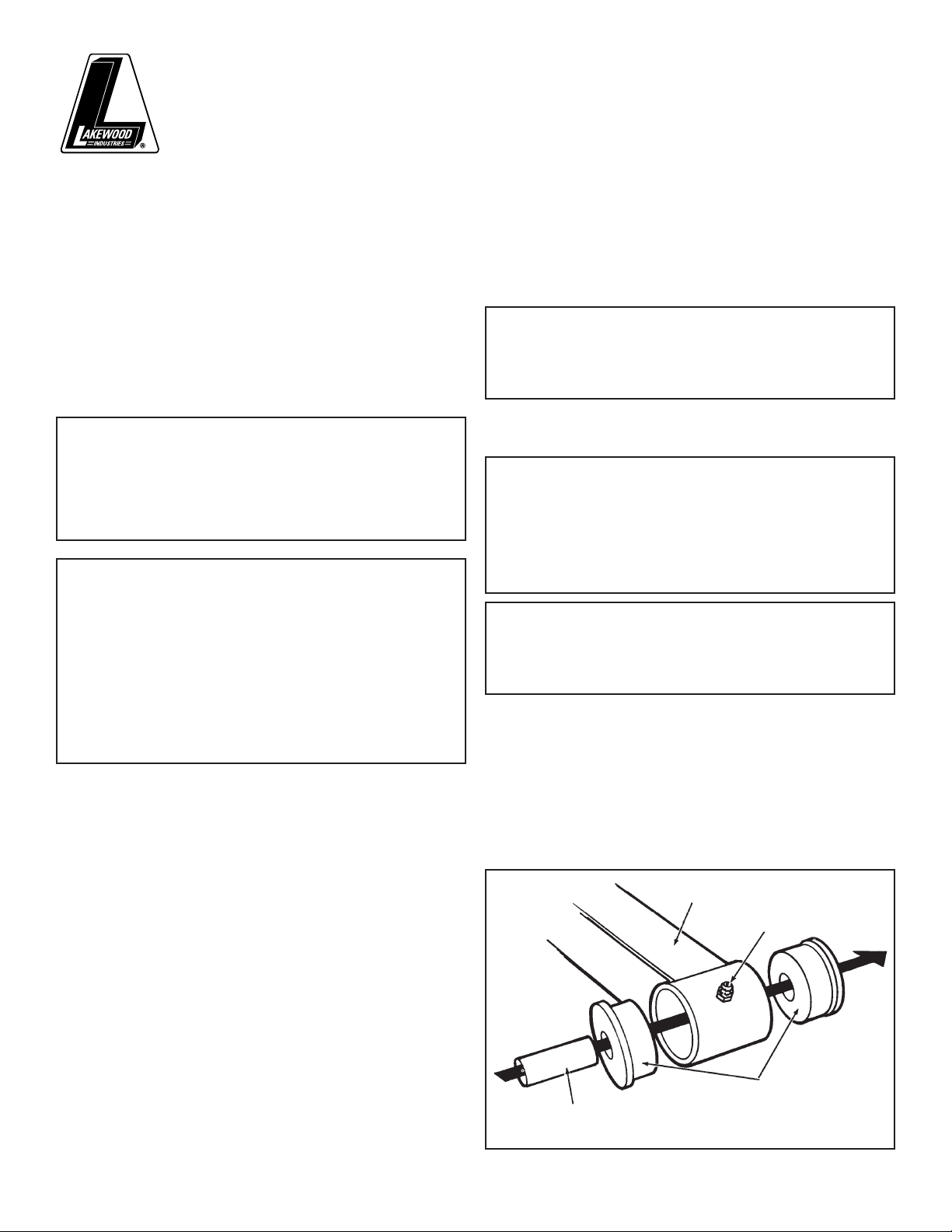
ILLUSTRATION #1
TRACTION
BAR
GREASE
FITTING
3. Raise rear of vehicle and support axle housing
using approved automotive support stands
having adequate load capacity.
TRACTION BAR ASSEMBLY
1. Install grease fittings (supplied) into each end
of traction bar by driving fittings into drilled
hole of bushing eyelet using a hammer and
either a 9/32” or 7mm socket. Use care not to
damage fittings
THE MR. GASKET PERFORMANCE GROUP • CLEVELAND • OHIO • WWW.MRGASKET.COM ©2001 REVISION 2
(see illustration #1)
.
STEEL
SLEEVE
URETHANE
BUSHINGS
Page 2
3. Remove lower shock absorber nut and lock
washer. Compress shock slightly to facilitate
removal of shock stud from axle housing
bracket.
Caution:
Shock absorbers are pressurized with gas,
use care when removing stud from bracket.
Carefully release shock allowing it to
extend all the way out.
4. Remove stabilizer bar from axle housing only
and let hang until new traction bars are
installed.
5. Remove factory lower control arm. DO NOT
discard the front bolts and nuts, they will be
reused.
Note:
If vehicle is equipped with emergency brake
cable bracket mounted to the factory
control arm bracket, let cable and bracket
hang temporarily.
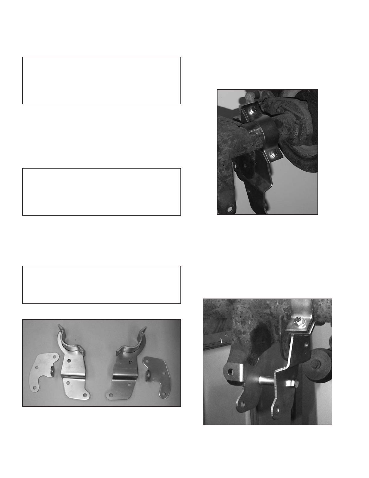
6. Place outer traction bar bracket into position on
the side of existing factory control arm bracket
located on the axle housing (upper part of
bracket will be spaced approximately 1” away
from the factory mounting bracket).
Note:
There are right and left-hand
inner/outer brackets.
Refer to photo # 1 for identification.
Install upper axle housing clamp and align
the clamp bolt holes with the lower bracket.
(See photo # 2)
. Install the 7/16-14 x 1-3/4”
hex head bolts (supplied). Thread on the 7/16-14
self-locking hex nuts and tighten only snug.
Use the supplied flat washers between the bolt
heads/hex nuts and bracket clamp surface.
7. Place inner traction bar bracket into position
on the side of the factory control arm bracket.
Align mounting holes for shock absorber
stud. Re-attach shock absorber stud to mount
hole and fasten with hex nut and lock washer
previously removed. DO NOT tighten securely
at this time
(see photo #3)
.
PHOTO #1
PHOTO #3
PHOTO #2
Right Hand Side Left Hand Side
Left Hand Driver’s Side Shown – Front View
Left Hand Driver’s Side Shown – Front View
Page 3

8. Install the front end of the Lakewood
Traction Bar to the front chassis mount using
the mounting hardware previously removed. DO
NOT tighten securely at this time.
Note:
Either end of the strut link may be connected
to the traction bar.
Note:
The traction bar should be installed with the load
control strut bracket facing down and positioned
toward the front.
9. Swing the rear of the bar up into the stock
factory mounting brackets. Align the holes in
the new mounting brackets with the existing
holes in the factory mounting brackets. Place
and align the 3/4” spacer and flatwasher
(supplied) between the factory outer bracket
and new outer bracket before installing the
mounting bolt
Factory
Outer
Bracket
Flat
Washer
(see photo #4)
PHOTO #4
.
Attach other end of strut link to lower holes
of new brackets on axle housing using a 15/16”
spacer (supplied) on each side of the ball rod
end (adjust load control strut to either shorten
or lengthen in order to align mounting holes
keeping the same amount of thread exposed
on each end of the strut). Fasten to the brackets
using the 1/2-20 x 4” hex head bolt and self
locking hex nut (supplied). Tighten only snug
at this time
(see photo #5).
PHOTO #5
Spacer
New
Outer
Bracket
Note:
If vehicle is equipped with emergency brake
cable bracket (previously removed),
DO NOT use the flatwasher. Use the spacer as
instructed above and position the cable
bracket over the new inner bracket and the
factory outer axle bracket. Cable bracket
will need to be spread apart slightly
in order to fit properly (see photo #4)
.
Install the new metric 12mm x 1.75 x 120mm
hex head bolt (supplied). Thread on the new
metric hex nut (supplied) and tighten only
snug at this time.
10. Attach the load control strut link to the bracket
on the traction bar using the
1/2-20 x 1-1/2” hex head bolt and self
locking hex nut (supplied). Tighten securely.
11. Position the long spacer tube between the new
brackets and align with the remaining holes
below the traction bar mount. Install the
1/2-20 x 4” hex head bolt (supplied) through
the bracket and spacer and thread on the self
locking hex nut
(as seen in photo #6)
.
Tighten securely.
Note:
If vehicle is equipped with emergency brake
cable bracket, use flat washers supplied
between 15/16” spacer and bracket and the
long spacer and bracket. If the vehicle does not
use emergency brake bracket DO NOT use the
flat washers supplied (see photo #6).
12. Securely tighten all traction bar mounting
bracket hardware at this time. Tighten front
and rear traction bar mounting bolts to
80 ft./lb. torque.
Page 4

RETAIN THIS INSTRUCTION SHEET
FOR FUTURE REFERENCE.
P/N 97144052 Rev. 12/01
13. Follow the same above procedure for
installation of Lakewood Traction Bar on
other side of vehicle.
14. When both traction bars are installed, re-
attach the stabilizer bar to the axle housing.
Tighten securely.
15. Lubricate both ends of the traction bars with a
good quality chassis grease.
16. Install wheels and properly tighten lug nuts to
wheel manufacturers specifications.
17. Carefully remove support stands and lower
vehicle to ground.
18. With vehicle on level surface, load control
strut links should be adjusted so that front
ball rod end mount has no load on it.
Adjust load control strut to either shorten
or lengthen in order to align mounting holes
so that bolt can be installed or removed
without any bind.
19. Tighten ball rod end mounting bolt and ball
rod end hex jam nuts securely.
This completes the installation. You can now
test drive the vehicle and will notice a big
improvement in traction control.
Important:
Periodically check to make sure that all
mounting hardware is securely tightened.
Use a good quality chassis grease to keep
bushings and sleeves properly lubricated.
Chassis Tuning Tips for Drag Racing
The stabilizer bar is not recommended for drag
racing. It is used to control body roll under
road handling conditions.
Recommended optional
Lakewood products:
• For drag racing, the factory rear shocks
should be replaced with a 50/50 ratio shock
absorber available for 1982-92 model years
(#40301).
• Replacement Bushing Set for Traction Bars
(#20538).
• Front Drag Struts are also available for
1982-92 model years in ratios of 70/30
(#40500) or 90/10 (#40510).
• Bolt-in Safety Drive Shaft Loop available for
1982-92 model years (#18020), 1993-2002
model years (#18022).
See your local retailer of Lakewood products
for specific prices.
TECHNICAL SERVICE
A highly trained technical service department is
maintained by Lakewood Industries to answer your
technical questions, provide additional product
information and offer various recommendations.
See your local retailer of Lakewood products for
specific prices. For best results, technical service
calls, correspondence and warranty questions
should be directed to the following address:
Lakewood Industries
10601 Memphis Ave., #12
Cleveland, Ohio 44140
Phone 216.688.8300
8:30 A.M.-5:00 P.M. EST
www.mrgasket.com
PHOTO #6
Left Hand Driver’s Side Shown – Rear View
Flat
Washers
Needed
 Loading...