

Page 1
1
1964-1972 (All GM A-Bodies) & 1978-1987 (All GM G-Bodies)
INSTALLATION INSTRUCTIONS
LAKEWOOD INDUSTRIES
LAKEWOOD
“TRACTION...ACTION” LIFT BARS
Part Number #21312 / 21313
WORK SAFELY!
For maximum safety, perform this installation on a
clean, level surface and with the engine turned off.
Place blocks or wedges in front of, and behind both
rear wheels to prevent movement in either direction.
CAUTION: To avoid any possibility of bodily injury or
damage to vehicle, do not attempt installation until
you are confident that the vehicle is safely secured
and will not move.
PREPARATION TIPS FOR INSTALLATION
1. Place vehicle on a solid level surface to ensure safe
installation.
2. Place wheel blocks in front of and behind both front
wheels to prevent movement in either direction.
3. Raise rear of vehicle and support axle housing using
approved automotive support stands having adequate
load capacity (6” inside from each control arm).
4. With a paint scraper, scrape all the undercoating
and rust off the inside of the frame and rear end lift
bar mounting areas.
GM LIFT BAR INSTALLATION
1. On a work bench, drive the grease fittings into the
1/4” holes in the front and rear of bars as follows:
Use a 1/4” deep well socket and a small hammer.
Place a small amount of bearing grease on the ball
end of each grease fitting so that the fitting will
temporarily stick to the end of the 1/4” socket.
Place the fitting into the hole, then one at a time,
drive them in.
2. Grease the ends of the front bar bushings and align
the nylon washers over the steel inner bushing. The
grease will hold the washers in place temporarily.
Also grease the inside of the front frame lift bar
mounting brackets.
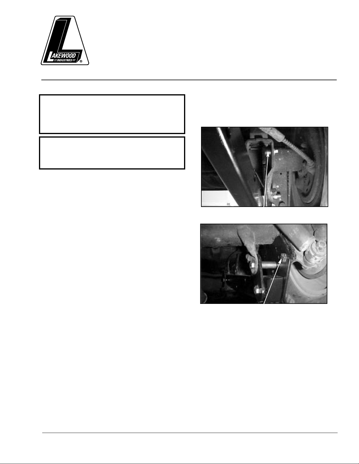
3. Place each lift bar into front frame brackets , align
bolt holes and insert the correct bolt supplied, from
the inside of the frame. Place self locking nut into
socket with extension then attach through the
outer frame holes.
4. Attach rear lift bar mounting plates as shown. use
the hardware supplied at the stock GM
lower control arm bolt holes. Place proper bolts
through these bolt holes and secure lock washers
and hex nuts. If preferred, thread locking liquid can
be used. Do not tighten fasteners yet.
5. Grease the ends of the rear bar bushings and place
nylon washers over the steel bushings just like in
step 2. Swing lift bars up between rear mounting
plates. Align the bolt holes and insert proper bolts
supplied. Attach lock washers and hex nuts and
tighten all bolts and nuts.
6. The pinion angle must now be checked and
adjusted if necessary. The angle between the drive
shaft and the rear end yoke must be between 4 and
6 degrees down. See pinion angle explanation sheet.
(SEE NUMBERS 1, 2, 3, 4 ON THE NEXT PAGE.)
7. With pinion angle set, tighten all fasteners securely.
8. A hole must be drilled through one of the rear lift
bar brackets (if not already drilled in)and through
(SEE NUMBER 4 ON THE NEXT PAGE.)
GM A-BODY
Small bushing used on the 21312 only
GM A-BODY. 64-72
GM A-BODY
Bolt here if not welding.
Page 2
LAKEWOOD INDUSTRIES
2
the housing brackets on each side. Using a hand
drill with a 1/2” chuck, drill 1/2” holes through the
rear mounting plates then through the factory lower
control arm housing brackets. Spot drill using a
1/4” drill, then change to a 1/4” drill size. Drill through
with the 1/4” drill bit then drill through with a 3/8” drill
bit and last with a 1/2” drill bit. CAUTION: Be very
careful when drilling through that the drill bit does not
grab and whip the drill around out of your hands.
9. Insert short 1/2” bolts, lock washers and nuts then
tighten securely.
10.Grease the four fittings in the bars through the
holes in bottom of bars.
11.If the anti-roll bar is going to be used, it can be
attached to the holes provided in the lift bars.
Place the spacers between the anti-roll bar and lift
bars (if necessary) on each side and use factory
GM bolts and nuts. tighten securely. NOTE: for
drag racing use, we recommend not using the
anti-roll bar.
12.Place car back on the ground and you are ready
to test.
CAUTION: TO USE YOUR LIFT BARS ARMS TO
ADJUST YOUR REAR END PINION ANGLE,
FOLLOW DIRECTIONS BELOW.
1. Remove car from jack stands. now place car upon
blocks or car ramps so that the car weight is on all
(4) wheels, keeping the car level, but making sure
you still have room to work under the car to make
your adjustments.
2. With the car up in the air you will need to check the
pinion angle of the rear end and drive shaft. Read
the attached sheet on setting pinion angle. You will
need to aquire a magnetic protractor (angle finder)
to do this operation.
3. Read this before performing the next operation ! !
Using a magnetic protractor (angle finder) check the
pinion angle. If you can’t obtain the desired 4-6
degree pinion angle, then loosen the 4 lower bolts
and pry between the shock stud and control arm to
adjust angle. Tighten all bolts securely while
checking pinion angle.
4. Do not attempt to drive the car with out securing
the lift bar plate to the axle housing plate welded or
bolted. Center punch and drill starting with 3/16” as
a pilot hole then step up the sizes using 1/4”, 5/16”,
3/8” and finishing with 1/2” for final size. Then
install the 1/2” bolts, lockwashers and nuts and
tighten. (torque to 65 ft lbs.)
5. Remove car from the support stands or car ramps
and place it on the ground. You are now ready to
Rock & Roll!!
PLEASE NOTE
1. Be sure to check the bolts frequently. make sure
they are tight and always stay tight. you can use
thread lock if you wish.
2. Welding is recommendedf (but not required) to
secure the lower plates to the lower axle brackets.
3. These lift bars are legal for use in NHRA stock
eliminator classes as a bolt on application only!
(no welding is allowed).
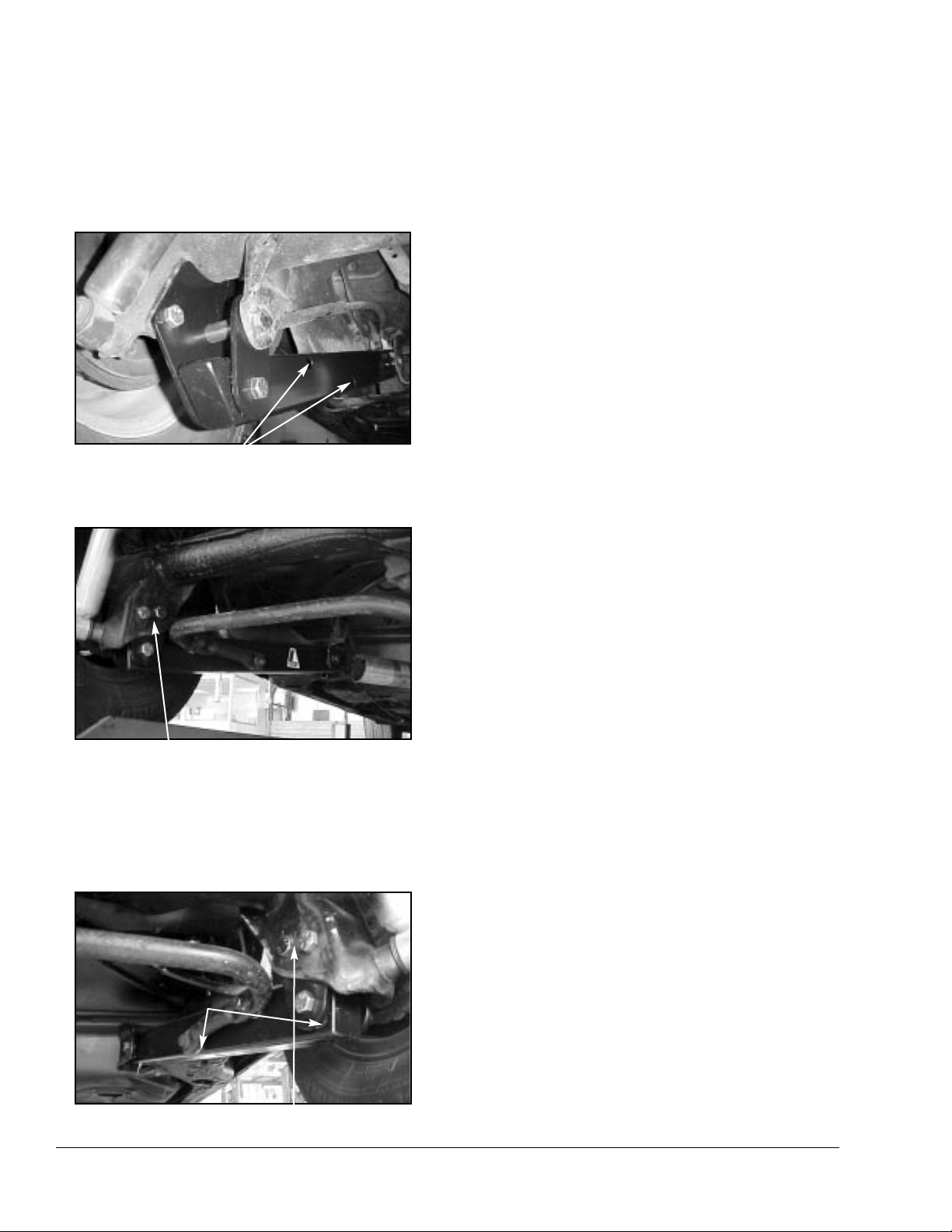
GM A-BODY
Sway bar holes.
GM G-BODY
2 bolts here if not welding.
Sway bar.
GM G-BODY
2 bolts here if not welding
Sway Bar
Sway Bar spacer bushings
Page 3

3LAKEWOOD INDUSTRIES
PINION ANGLE
Pinion angle affects the efficiency of power
transmission from the driveshaft to the rearend. The
pinion angle is the difference between the pinion
centerline and the driveshaft centerline. for maximum
performance, the ideal is to have a slight pinion down
angle (min. 2 degrees) under full power. Obviously, the
pinion angle changes as power is applied, so the axle
housing begins to twist as the pinion tries to drive the
ring gear. Rear axle wind-up can take some of the
intial energy or “hit” away from the launch. As a
general rule, a leaf spring rear suspension should
have between 5-7 degrees of static pinion angle
(pinion down); and a factory four-link should be set
between 4-6 degrees.
Keep in mind that these pinion angles are for
competition. If you primarily drive your car on the
street, you shouldn’t have more than a 5 degree
angle, max. The u-joints are designed to run at this
angle, which allows the cups to rotate, avoiding
premature wear and failure. This doesn’t affect leaf
spring supension, since it runs well within this
tolerance.
You will need to have the car level, up on (4) car
ramps or blocks of equal heights, so you have room
to work under the car when checking the pinion
angle. Also, both the front and rear suspensions need
to be loaded to get accurate readings. The height of
the rearend (relative to the rest of the driveline) will
affect the pinion angle. Using an angle finder, which is
a tool the combines a bubble level and protractor, to
determine the correct pinion angle for your car.
Position the angle finder on the driveshaft and record
the measurement, and then place the angle finder on
the pinion (the u-joint yoke rotated to vertical position
will give an accurate reading) and record the
measurment. The pinion angle is a combination of the
two measurements.
EXAMPLES:
(pinion 0 degrees & driveshaft 6 degrees = 6 degrees total )
(pinion 2 degrees & driveshaft 4 degrees = 6 degrees total )
(pinion 3 degrees & driveshaft 3 degrees = 6 degrees total )
(pinion 4 degrees & driveshaft 2 degrees = 6 degrees total )
(pinion 6 degrees & driveshaft 0 degrees = 6 degrees total )
OTHER SUSPENSION TIPS!
THE FOLLOWING ARE FINE TUNING TIPS FOR
YOUR SUSPENSION
You can purchase shocks that are 3 position
adjustable for both front and rear applications. These
shocks are available from your local speed shop, or
other suppliers. If you can’t find shocks designed for
your specific application, you’ll have to check in a
shock catalog for O.E. applications. You may have to
use shocks from another make or model that has the
same mounts at each end, and the same length, or an
inch or two longer, which won’t hurt, because it allows
for more suspension travel, so you don’t hit the end of
your shock travel and pull the rear wheels off the
ground.
LEAF SPRING REAR SUSPENSION
With Lakewood lift bars, there are shims supplied with
the bars that are used to put more preload in the bars.
When installing the bars always put one more shim on
the right side (pass. side) than the left side (drivers
side). This extra shim helps to counteract engine
torque wanting to lift the left front corner. Use 90/10
front shocks on small blocks, 80/20 or 70/30 with big
blocks and high horsepower small blocks. use 50/50
shocks on the rear.
COIL SPRING REAR SUSPENSION
Use 90/10 front shocks on small block cars, 80/20 or
70/30 on big blocks cars, and high horsepower small
blocks. Except on short wheel base cars like
Mustangs and Capri’s, use the 80/20 or 70/30
settings. Use 50/50 rear shocks along with an air bag
in the right rear coil spring only (4-8 lbs. air), this you
will have to play with to find the best setting for your
car. The air bag is used to counteract the engine
torque wanting to lift the left front corner.
CHASSIS WORK
To help the effects of the lift bars, a minimum of six
point cage to stiffen the chassic up would help. That
way the chassis is not absorbing the energy hit or the
bars, and all the energy will be directed to the tires, to
help lay out a bigger footprint.
**NOTE: THIS DRAWING IS AN
EXAGGERATION.
THE PINION ANGLE IS THE RELATION
BETWEEN THE PINION CENTERLINE
AND THE DRIVESHAFT CENTERLINE.
Page 4

Recommended chassis modifications:
For serious drag racing, we recommend
reinforcing the upper and lower control arm
chassis mounts. They are only spot welded
in place from the factory but should be fully
welded to the floor pan for added strength.
T uning Tips:
These traction bars can be attached to the axle
housing brackets in 1 of 2 positions. The lower
holes will cause the rear tires to “plant” harder
than the upper holes. If you have too much
traction, move the rear attachment to the upper
holes of the axle housing brackets.
Illustration #2
shows what happens to the
instant center (imaginary intersection point
between the upper and lower control arms)
when the lower control arms are attached to
each of the two optional mounting holes in the
axle housing brackets.
When the differential pinion gear is turned by
the drive shaft, which is driven by the engine,
the pinion gear turns the ring gear causing the
axle housing to rotate, pulling back on the upper
control arms and pushing forward on the lower
control arms. These forces theoretically meet
at the instant center point (as shown on the
illustration). The shorter the instant center point
is, the more the tires will separate from the body
upon launch.
IMPORTANT!
Periodically check to make sure that all mounting
hardware is securely tightened. Use a good
quality chassis grease to keep bushings and
sleeves properly lubricated.
TECHNICAL SERVICE
A highly trained technical service department is
maintained by Lakewood Industries to answer your
technical questions, provide additional product
information and offer various recommendations. See
your local retailer of Lakewood products for specific
prices. For best results, technical service calls,
correspondence and warranty questions should be
directed to the following address:
Lakewood Industries
10601 Memphis Ave. #12
Cleveland, Ohio 44144
Phone 216-688-8300
8:30 A.M.-5:00 P.M. EST
www .mrg asket.com
Recommended Optional
Lakewood Products:
• For drag racing, the factory rear shocks
should be replaced with a 50/50 ratio shock
absorber available for 1982-92 model years
(#40301).
• Replacement Bushing Set for Traction Bars
(#20538).
• Front Drag Struts are also available for
1982-92 model years in ratios of 70/30
(#40500) or 90/10 (#40510).
• Bolt-in Safety Drive Shaft Loop available for
1982-92 model years (#18020), 1993-2002
model years (#18022).
See your local retailer of Lakewood products
for specific prices.
LAKEWOOD IS A DIVISION OF THE MR. GASKET PERFORMANCE GROUP
10601 MEMPHIS AVE. #12, CLEVELAND, OH 44144 • 216.688.8300 EXT. 500
VISIT US ON THE WEB AT: www.mrgasket.com or via e-mail at tech@mrgasket.com
Made in U.S.A.
Printed in U.S.A.
Form# 97140080
STOCK
LOCATION
B
A
LOWER CONTROL ARM ATTACHING POINT
ILLUSTRATION #2
 Loading...