

Page 1
PTFE PTFE
Page 2
MOUNTING PROCEDURE
Step 1
Mount the pump as close as possible to the fuel tank (at or below the level of the fuel
tank pickup) in a well ventilated area with minimual exposure to road debris. Avoid
exposing the pump and fuel lines to moving parts and hot surfaces, such as the
exhaust system. NOTE: Increasing distance between the pump and tank will
decrease pump efficiency.
Step 2
Using the pump mounting bracket as a template, locate mounting holes on a solid
member, such as the vehicle shassis. Drill holes for 5/16 bolts. See Figure 1. NOTE:
To ensure against a potential fire hazard from pump flooding, mount the
pump in a vertical position with the motor on top.
Step 3
Connect fuel lines as shown in Figure 2 (A, B, C, or D). If your fuel system requires
a fuel pressure regulator, proceed to the instructions with the fuel pressure regulator.
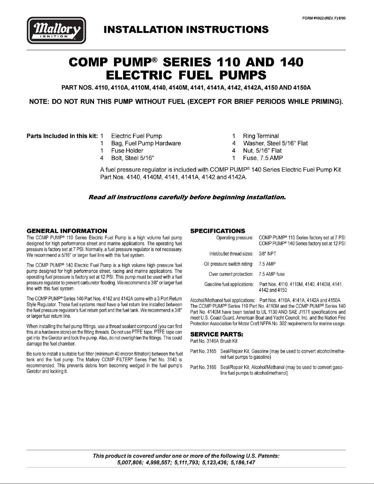
FIGURE 1
BLACK WIRE
()
3/8" NPT
OUTLET
BYPASS ADJUSTMENT
(BYPASS PLUG AND JAM
NUT)
TOP
RED WIRE
(+)
3/8" NPT
INLET
BOTTOM
WIRING PROCEDURE
Wiring the pump to an oil pressure switch will provide power only when the ignition
switch is on and the engine is running. This will prevent the pump from running if your
engine stalls. Use 14 gauge wire or larger and be sure to disconnect the battery
ground cable before wiring the pump. Refer to Figure 3 when connecting the pump to
an oil pressure switch.
The pump may be wired directly to the ignition switch ON terminal and grounded to
the frame or battery. Refer to Figure 4 when connecting the pump to the ignition switch
ON terminal.
MAINTENANCE PUMP DISASSEMBLY
If your pump fails to produce adequate pressure, it may require cleaning. Follow the
steps below to disassemble and clean your Mallory Electric Fuel Pump. Refer to
Figure 5 while performing the following steps.
Step 1
Remove the pump from the vehicle and clean pump exterior. Place the pump on its
side on a clean work surface. Scribe or draw a line acrosss the pump housing, port
plate and fuel chamber so that you can reassemble the pump correctly.
Step 2
Remove the two fuel chamber screws from the bottom of the pump. Remove the fuel
chamber and port plate. NOTE: Do not drop the Gerotor from the pump cavity.
Step 3
Separate the port plate from the fuel chamber. Inspect the flame arrestor screen in the
fuel chamber and clean it if necessary.
Step 4
Place your hand beneath the Gerotor and hold the pump in an upright position. The
Gerotor should slide out of the pump housing and into your hand. NOTE: Observe the
position of the Gerotor and be careful not to reverse it when you reassemble
the pump.
Step 5
Release the jam nut on the bypass plug. Mark the bypass plug location and count the
number of turns required to remove it. Remove the bypass spring and plunger.
Inspect the plunger. The plunger surface should be clean and slide freely in the
chamber. Check the plunger pad and remove any debris embedded in its surface.
Reinstall the bypass spring and plunger. Clean the bypass plug. Apply thread sealant
compound to the bypass plug threads. Install the bypass plug. Tighten the jam nut.
Step 6
Clean the Gerotor and install it in the pump housing. Inspect the O-ring and gasket.
Replace them if necessary. Place the gasket and port plate on the fuel chamber. Install
the fuel chamber assembly on the pump housing. Torque the fuel chamber screws to
24 in/lbs.
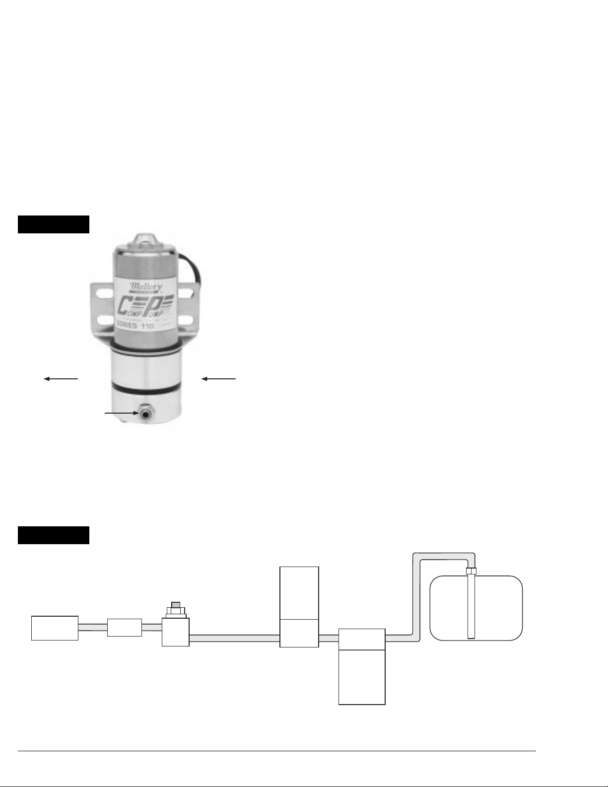
FIGURE 2A
FUEL PUMP KIT PART NO. 4110 (OPTIONAL FUEL
PRESSURE REGULATOR), 4140 OR 4141 WITH FUEL
PRESSURE REGULATOR PART NO. 4207 OR 4209
FUEL
FILTER
CARB.
REGULATOR
2
FUEL
PUMP
FUEL
FILTER
FUEL
TANK
COMP® FILTER
PART NO.
3140
Page 3

FIGURE 2B
FUEL PUMP KIT PART NO. 4142 WITH FUEL
PRESSURE REGULATOR PART NO. 4309
FUEL
PUMP
FUEL
FILTER
CARB.
FUEL RETURN
REGULATOR
FIGURE 2C
FUEL PUMP KIT PART NO. 4140 OR 4141 WITH FUEL PRESSURE
REGULATOR PART NO. 4207 OR 4209
FUEL
PUMP
FUEL
FILTER
CARB.
REGULATOR
FIGURE 2D
FUEL SYSTEM FOR NITROUS OXIDE FUEL PUMP KIT
PART NO. 4142 WITH FUEL PRESSURE REGULATOR
PART NO 4309
FUEL
PUMP
FUEL
FILTER
COMP® FILTER
PART NO.
3140
COMP® FILTER
FUEL
TANK
FUEL
FILTER
PART NO.
3140
NITROUS SYSTEM
GAS SOLENOID
FIGURE 3
FROM
VEHICLE
BATTERY
GROUND
FUEL
FILTER
REGULATOR
FUEL RETURN
IGNITION SWITCH OIL PRESSURE
TO ACCESSORIES
NORMALLY
TO COIL (+)
VEHICLE
BATTERY
SWITCH
OPEN
COMMON
NORMALLY
CLOSED
STARTER
FUSE (7.5 AMP)
RED BLACK
12 VOLT OUTPUT TERMINAL
ON STARTER THAT HAS 12
VOLT ONLY WHILE STARTER
IS CRANKING
FUEL
PUMP
FUEL
TANK
GROUND
3
Page 4

IGNITION SWITCH
FIGURE 4
TO ACCESSORIES
FROM
VEHICLE
BATTERY
FIGURE 5
14
13
12
11
TO COIL (+)
FUSE (7.5 AMP)
1 JAM NUT
2 BYPASS PLUG
3 BYPASS SPRING
4 SCREW, FUEL CHAMBER (2)
5 BYPASS PLUNGER
6 PAD, BYPASS PLUNGER
7 SCREEN, FLAME ARRESTER
8 FUEL CHAMBER
9 GASKET, FUEL CHAMBER
10 PORT PLATE
11 GEROTOR
12 O-RING
13 GEROTOR HOUSING
14 MOTOR
COMP PUMP® SERIES 110 FLOW VS. PRESSURE @12.5VDC
(FLOW INCREASES AS PRESSURE DECREASES)
FUEL
PUMP
BLACKRED
GROUND
10
7.5
6.0
4.5
3.0
9
8
7
6
5
4
3
2
1
1.5
PRESSURE PSI
FLOW RATE GPH
COMP PUMP® SERIES 140 FLOW VS. PRESSURE @12.5VDC
15
12
9
6
3
PRESSURE PSI
FLOW RATE GPH
25
(FLOW INCREASES AS PRESSURE DECREASES)
30
50 75 100 125
60 90 120 150
MALLORY IS A DIVISION OF THE MR. GASKET PERFORMANCE GROUP
550 MALLORY WAY, CARSON CITY, NEVADA 89701
(775) 882-6600 FAX (775) 887-4326
www.mrgasket.com
FORM #1022
REV. F (8/00)
MADE IN USA
PRINTED IN USA
4
 Loading...