

Page 1
Application Guide Aluminum Electrolytic Capacitors
This Application Guide
This guide is a full handbook on aluminum electrolytic
capacitors, of course with emphasis on Cornell
Dubilier’s types. It covers construction in depth and
discloses the latest information on performance and
application for the major aluminum electrolytic types
made worldwide. We encourage you to tell us what more
you’d like to know, so we can improve this guide.
Aluminum Electrolytic Capacitor Overview
Except for a few surface-mount technology (SMT) aluminum electrolytic capacitor types with solid electro
lyte systems an aluminum electrolytic capacitor con
sists of a wound capacitor element, impregnated with
liquid electrolyte, connected to terminals and sealed in
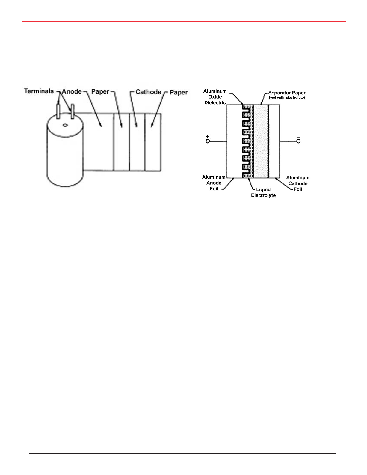
a can. The element is comprised of an anode foil, paper
separators saturated with electrolyte and a cathode foil.
The foils are high-purity aluminum and are etched with
billions of microscopic tunnels to increase the surface
area in contact with the electrolyte.
While it may appear that the capacitance is between the
two foils, actually the capacitance is between the anode
foil and the electrolyte. The positive plate is the anode
foil; the dielectric is the insulating aluminum oxide on
the anode foil; the true negative plate is the conductive,
liquid electrolyte, and the cathode foil merely connects
to the electrolyte.
They are polar devices, having distinct positive and negative terminals, and are offered in an enormous va
-
-
riety of styles which include molded and can-style SMT
devices, axial and radial-leaded can styles, snap-in terminals styles and large-can, screw terminal styles. Rep
resentative capacitance-voltage combinations include
330 µF at 100 V and 6800 µF at 10 V for SMT
devices
100 µF at 450 V, 6,800 µF at 50 V and 10,000
µF at 10 V for miniature-can styles,
1200 µF at 450 V and 39,000 µF at 50 V for
snap-in can styles and
9000 µF at 450 V and 390,000 µF at 50 V for
large-can, screw-terminal styles.
-
-
This construction delivers colossal capacitance because
etching the foils can increase surface area more than
100 times and the aluminum-oxide dielectric is less
than a micrometer thick. Thus the resulting capacitor
has very large plate area and the plates are awfully close
together.
These capacitors routinely offer capacitance values from
0.1 µF to 3 F and voltage ratings from 5 V to 550V.
Capacitor Construction
Rilled
Construction
If two, same-value, aluminum electrolytic capacitors are
connected in series, back-to-back with the positive ter
minals or the negative terminals connected, the result
ing single capacitor is a non-polar capacitor with half
the capacitance. The two capacitors rectify the applied
voltage and act as if they had been bypassed by diodes.
When voltage is applied, the correct-polarity capacitor
gets the full voltage. In non-polar aluminum electrolytic
capacitors and motor-start aluminum electrolyte capaci
tors a second anode foil substitues for the cathode foil to
achieve a non-polar capacitor in a single case.
-
-
-
CDM Cornell Dubilier • 140 Technology Place • Liberty, SC 29657 • Phone: (864)843-2277 • Fax: (864)843-3800 • www.cde.com
Page 2
Application Guide Aluminum Electrolytic Capacitors
Miniature,
Radial-Leaded T
ype
Snap-in T
ype
Aluminum
Lead Wire
Tabs
Sleeve
Rubber
Can
Capacitor
Element
Terminal
Rubber
Top Disc
Phenolic Disc
Aluminum Tabs
Capacitor Element
Tape
Can
Sleeve
Capacitor Construction
Conventional Cornell Dubilier
Construction Thermal Pak
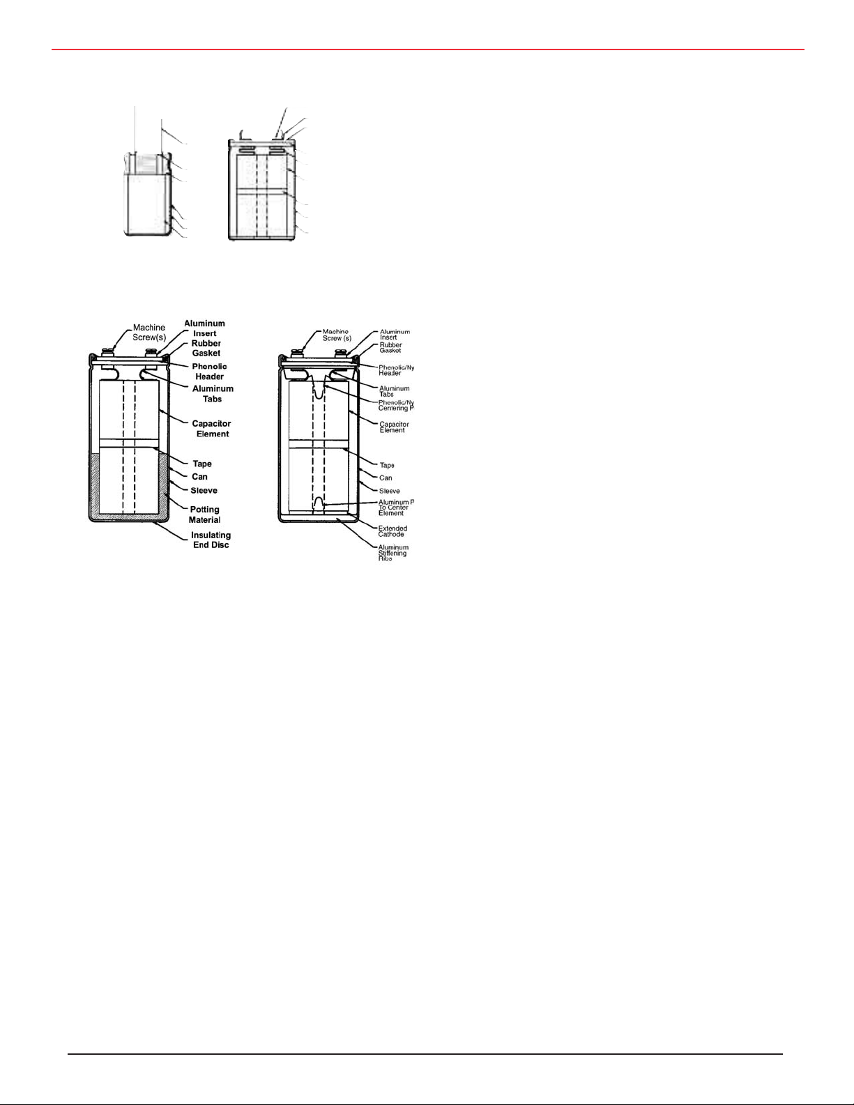
These figures show typical constructions of the
non-surface-mount aluminum electrolytic capacitors.
Most Cornell Dubilier capacitors use compression-fit
construction so there is no thermoplastic potting com
pound to interfere with safety-vent operation. Thermal
Pak™ and Rilled are Cornell Dubilier’s unique con
structions for computergrade, screw terminal capacitors. Compared to conventional, potted construction,
they operate cooler, provide longer life, withstand
higher shock and vibration, deliver more reliable safe
ty vent operation and are lighter weight.
Etching
The anode and cathode foils are made of high purity,
thin aluminum foil, 0.02 to 0.1 mm thick. To increase
the plate area and the capacitance, the surface area in
contact with the electrolyte is increased by etching the
foils to dissolve aluminum and create a dense network
of billions of microscopic tunnels penetrating through
the foil. Etching involves pulling the aluminum foil on
rollers through a chloride solution while applying an
AC, DC or AC-and-DC voltage between the etch solution and the aluminum foil. Surface area can increase
CDM Cornell Dubilier • 140 Technology Place • Liberty, SC 29657 • Phone: (864)843-2277 • Fax: (864)843-3800 • www.cde.com
as much as 100 times for foil in low-voltage capacitors
and 20 to 25 times for high-voltage capacitors.
Forming
The anode foil carries the capacitor’s dielectric. The di
electric is a thin layer of aluminum oxide, Al
2O3
is chemically grown on the anode foil during a process
called “formation.” Formation is accomplished by pull
ing the anode foil on rollers through an electrolyte bath
and continuously applying a DC voltage between the
bath and the foil. The voltage is 135% to 200% of the
final capacitor’s rated voltage. The thickness of the alu
minum oxide is about 1.4 to 1.5 nm for each volt of
the formation voltage, e.g., the anode foil in a 450 V
capacitor may get a formation voltage in excess of 600
V and have an oxide thickness of about 900 nm. That’s
less than a hundredth the thickness of a human hair.
Formation reduces the effective foil surface area because the microscopic tunnels are partially occluded by
the oxide. The tunnel etch pattern is adjusted by choice
of foil and etching process so that low-voltage anodes
have dense tunnel patterns compatible with thin oxide
and high-voltage anodes have coarse tunnel patterns
compatible with thick oxide. The cathode foil is not
formed and it retains its high surface area and dense
etch pattern.
Slitting
Foil is etched and formed in jumbo rolls of 40 to 50 cm
wide and then slit into various widths according to the
lengths of the final capacitors.
Winding
The capacitor element is wound on a winding machine
with spindles for one-to-four separator papers, the an-
ode foil, another set of one-to-four separator papers and
the cathode foil. These are wound into a cylinder and
wrapped with a strip of pressure-sensitive tape to prevent unwinding. The separators prevent the foils from
touching and shorting, and the separators later hold the
reservoir of electrolyte.
Before or during winding aluminum tabs are attached
to the foils for later connection to the capacitor terminals. The best method is by cold-welding of the tabs to
the foils with tab locations microprocessor controlled
during winding so that the capacitor element’s inductance can be less than 2 nH.
-
, that
-
-
Page 3
Application Guide Aluminum Electrolytic Capacitors
The older method of attachment is by staking, a process
of punching the tab through the foil and folding down
the punched metal. Cold welding reduces short-circuit
failures and performs better in high-ripple current and
discharge applications in which the individual stakes
may fail from high current like buttons popping off one
at a time from a fat-man’s vest.
Wound Capacitor Elements
Connecting Terminals
conduction. Common solvents are ethylene glycol
(EG), dimethylformamide (DMF) and gammabutyro
lactone (GBL). Common solutes are ammonium borate
and other ammonium salts. EG is typically used for ca
pacitors rated –20 °C or –40 °C. DMF and GBL are
often used for capacitors rated –55 °C.
-
-
In SMT capacitors and miniature capacitors with rub
ber bungs, extensions of the tabs are the capacitor terminals. But in large can capacitors like snap-ins and
screw terminal styles, the tabs are riveted or welded
on the underside of the capacitor tops to terminal inserts. Welding produces the lowest contact resistance
and highest current handling. Both resistive welding
and ultrasonic welding are used. The up to 12 tab pairs
that may be used in large screw terminal capacitors often require more mechanical support during assembly
so the tabs in such capacitors may be both riveted to
post extensions on the terminals and then welded. In an
axial-leaded capacitor the cathode tab is welded to the
can before sealing.
Impregnation
The capacitor element is impregnated with electrolyte
to saturate the paper separators and penetrate the etch
tunnels. The method of impregnation may involve
immersion of the elements and application of vacuumpressure cycles with or without heat or, in the case of
small units, just simple absorption. The electrolyte is
a complex blend of ingredients with different formu
lations according to voltage and operating temperature
range. The principal ingredients are a solvent and a
conductive salt – a solute – to produce electrical
-
Water in the electrolyte plays a big role. It increases
conductivity thereby reducing the capacitor’s resis
tance, but it reduces the boiling point so it interferes
with high temperature performance, and it reduces
shelf life. A few percent of water is necessary because
the electrolyte maintains the integrity of the aluminum
oxide dielectric. When leakage current flows, water is
broken into hydrogen and oxygen by hydrolysis, and
the oxygen is bonded to the anode foil to heal leakage
sites by growing more oxide. The hydrogen escapes by
passing through the capacitor’s rubber seal.
Sealing
The capacitor element is sealed into a can. While most
cans are aluminum, phenolic cans are often used for
motorstart capacitors. In order to release the hydrogen
the seal is not hermetic and it is usually a pressure clo
sure made by rolling the can edge into a rubber gasket,
a rubber end-plug or into rubber laminated to a phenolic board. In small capacitors molded phenolic resin
or polyphenylene sulfide may replace the rubber. Too
-
tight a seal causes pressure build up, and too loose a
seal shortens the life by permitting drying out, loss of
electrolyte.
Capacitor-Element Materials
-
-
CDM Cornell Dubilier • 140 Technology Place • Liberty, SC 29657 • Phone: (864)843-2277 • Fax: (864)843-3800 • www.cde.com
Page 4

Application Guide Aluminum Electrolytic Capacitors
Aging
Here the capacitor assembly comes full circle. The last
manufacturing step is “aging” during which a DC voltage
greater than the rated voltage but less than the formation
voltage is applied to the capacitor. Usually the voltage is ap
plied at the capacitor’s rated temperature, but other temperatures and even room temperature may be used. This
step reforms the cut edges and any damaged spots on the an
ode foil and covers any bare aluminum with aluminum oxide
dielectric. Aging acts as burn-in and reduces or eliminates
early life failures (infant mortals). Low, initial DC leakage
-
current is a sign of effective aging.
Comparison to Other Types of Capacitors
Ceramic Capacitors
Ceramic capacitors have become the preeminent, general
purpose capacitor, especially in SMT chip devices where
their low cost makes them especially attractive. With the
emergence of thinner-dielectric, multilayer units with rated
voltages of less than 10 V capacitance values in the hundreds
of microfarads have become available. This intrudes on the
traditional, high-capacitance province of aluminum electro
lytic capacitors.
Ceramic capacitors are available in three classes according
to dielectric constant and temperature performance. Class 1
(NPO, COG) is suitable for low capacitance, tight tolerance
applications in the range of 1 pF to a few mF. Class 2 (X7R)
has 20 to 70 times as much capacitance per case size, but ca
pacitance typically varies about ± 10% over its –55 to 125 °C
temperature range. The maximum change is +15 % to –25%.
Class 3 (Z5U) with about 5 times the capacitance of Class
2 has wild swings of capacitance with voltage and temperature. The temperature range is –25 °C to 85 °C, and capacitance varies about +20% –65% over the range. Ceramic chip
capacitors are brittle and sensitive to thermal shock, so precautions need to be taken to avoid cracking during mounting,
especially for high-capacitance large sizes.
The typical temperature range for aluminum electrolytic
capacitors is –40 °C to 85 °C or 105 °C. Capacitance var
ies about +5% –40% over the range with the capacitance
loss all at cold temperatures. Capacitors rated –55 °C generally only have –10 % to –20 % capacitance loss at –40 °C.
Cold temperature performance for rated voltages of 300 V
and higher is often worse, and temperature performance var
ies by manufacturer. Thus Class 1 and 2 ceramic capacitors
perform better than aluminum electrolytic capacitors at cold
temperatures, and Class 3 ceramic capacitors perform worse
at all temperatures.
Aluminum electrolytic capacitors readily deliver much
more capacitance. Aluminum electrolytic capacitors give
more capacitance and energy storage per unit volume than
ceramic capacitors for all types except for low-voltage,
Class 3 ceramic SMT chip capacitors. While tolerances of
±5% and ±10% are routine for ceramic capacitors, ± 20%
and –10% +50% are the norms for aluminum electrolytic.
This makes aluminum electrolytics the choice for high capacitance applications like rectification filters and power
holdup where more capacitance is a bonus. Ceramic ca
pacitors are not polarized and therefore can be used in AC
applications. The low DF and high capacitance stability of
Class 1 and 2 are especially suited to AC and RF applica
-
tions. By comparison, aluminum electrolytic capacitors are
polarized and cannot withstand voltage reversal in excess of
1.5 V. While non-polar aluminum electrolytics are available
for momentary-duty AC applications like motor starting and
voltage-reversing applications, the high DF of aluminum
electrolytic capacitors – from 2% to 150% – causes excess
heating and short life in most AC applications.
-
Ceramic capacitors are generally no more reliable than alu
minum electrolytic capacitors because aluminum electrolytics self heal. Since high-capacitance ceramic capacitors may
develop micro-cracks, aluminum electrolytic capacitors are
preferred for high capacitance values. However, small sizes
of aluminum electrolytic capacitors may have limited life
due to dry out, so consider reliability in your choice for applications operating at high temperatures, over 65 °C.
Film Capacitors
Film capacitors offer tight capacitance tolerances, very low
-
leakage currents and small capacitance change with temperature. They are especially suited to AC applications through
their combination of high capacitance and low DF that permits high AC currents. However, they have relatively large
sizes and weights.
-
The popular polymers used for plastic-film dielectric
tors are polyester and polypropylene. The popular polymer
for SMT devices is polyphenylene sulfide (PPS). While film/
foil construction is often used for small capacitance values
– less than 0.01 µF – and for high-current applications, metallized-film is usually preferred because it gives smaller size,
lower cost and is self healing. Film capacitors are generalpurpose capacitors for through-hole applications and have
special uses for tight-tolerance, AC voltage, high voltage and
snubbing.
Polyester film capacitors operate from –55 °C to 85 °C at
-
-
-
-
capaci-
CDM Cornell Dubilier • 140 Technology Place • Liberty, SC 29657 • Phone: (864)843-2277 • Fax: (864)843-3800 • www.cde.com
Page 5
Application Guide Aluminum Electrolytic Capacitors
rated voltage; +85 °C to 125 °C with linear voltage deratingto 50% rated voltage. The typical capacitance change over
the entire range is less than –5% +15% with ±1% from 0 °C
to 50 °C. Capacitance values are readily available up to 10
µF with special large sections to 100 µF. Generally available
voltages are 50 to 1000 Vdc and 35 to 600 Vac. AC current
handling is limited by polyester’s high temperature DF of
about 1%.
Polypropylene film capacitors operate from –55 °C to 85 °C
at rated voltage; 85 °C to 105 °C with linear voltage derating
to 50% rated voltage. The typical capacitance change over
the entire range is less than +2% –4% with ±1% from –20
°C to 60 °C. Capacitance values are readily available up to
65 µF with special large sections to 1000 µF. Generally avail
able voltages are 100 to 3000 Vdc and 70 to 500 Vac. AC
current handling permits use in motor-run and other continu
ous duty AC applications.
Compared to aluminum electrolytic capacitors, film capaci
tors take teh lead in high voltage, AC voltage and tight toler
ance applications. Aluminum electrolytics excel in capacitance and energy storage.
Solid Tantalum Capacitors
Like aluminum electrolytic capacitors solid tantalum
capacitors are polar devices (1 V maximum reverse voltage),
having distinct positive and negative terminals and are of
fered in a variety of styles. Case styles include both molded
and conformal-coated versions of
radial, axial and surface
mount configurations. Typical capacitance values are from
0.1 µF to 1000 µF in voltage ratings from 2 V to 50 V. Typical maximum capacitance-voltage combinations are approximately 22 µF at 50 V for leaded styles and 22 µF at
35 V for surface mount. Strengths are temperature stability,
volumetric efficiency and compatibility with all automated
assembly systems. Weaknesses are the limited voltage and
capacitance ranges and a short-circuit failure mode accompanied by catching fire.
The operating temperature range is –55 °C to 85 °C at rated
voltage; +85 °C to 125 °C with linear voltage derating to
2/3 rated voltage. The typical capacitance change over the
entire range is less than ±5%. Thus aluminum electrolytic
-
capacitors have a much broader voltage and capacitance
ranges than solid tantalum capacitors but perform worse at
-
cold temperature.
Solid tantalum capacitors are generally considered more re
-
liable than aluminum electrolytic capacitors because solid
-
tantalum capacitors do not wear out. Their failure rate decreases with time, while aluminum electrolytic capacitors
wear out by drying out. As a practical matter, dry-out only
affects the smallest capacitors operating in high-temperature
environments.
Larger aluminum electrolytics do not dry out in the 10 to 20
-
years expected of most applications, and the open-circuit,
dry-out failure is benign compared to solid-tantalum’s short
circuit failure mode.
-
Characterization
Resistance Rs is the equivalent series resistance, and it
CIRCUIT MODEL
Capacitance occurs when two electrical conductors are separated by an insulator. A capacitor is an electronic component
optimized to deliver capacitance. The capacitance in pF is
C = 0.08855(n-1) ε A/d
Where n is the number of plates for electrodes, ε is the
dielectric constant, A is the plate surface area in cm
is the thickness of the dielectric between the plates in cm.
Dielectric constant is the multiplier increase in capacitance
that the dielectric delivers compared to a vacuum. The
dielectric constant for aluminum oxide is about 8.
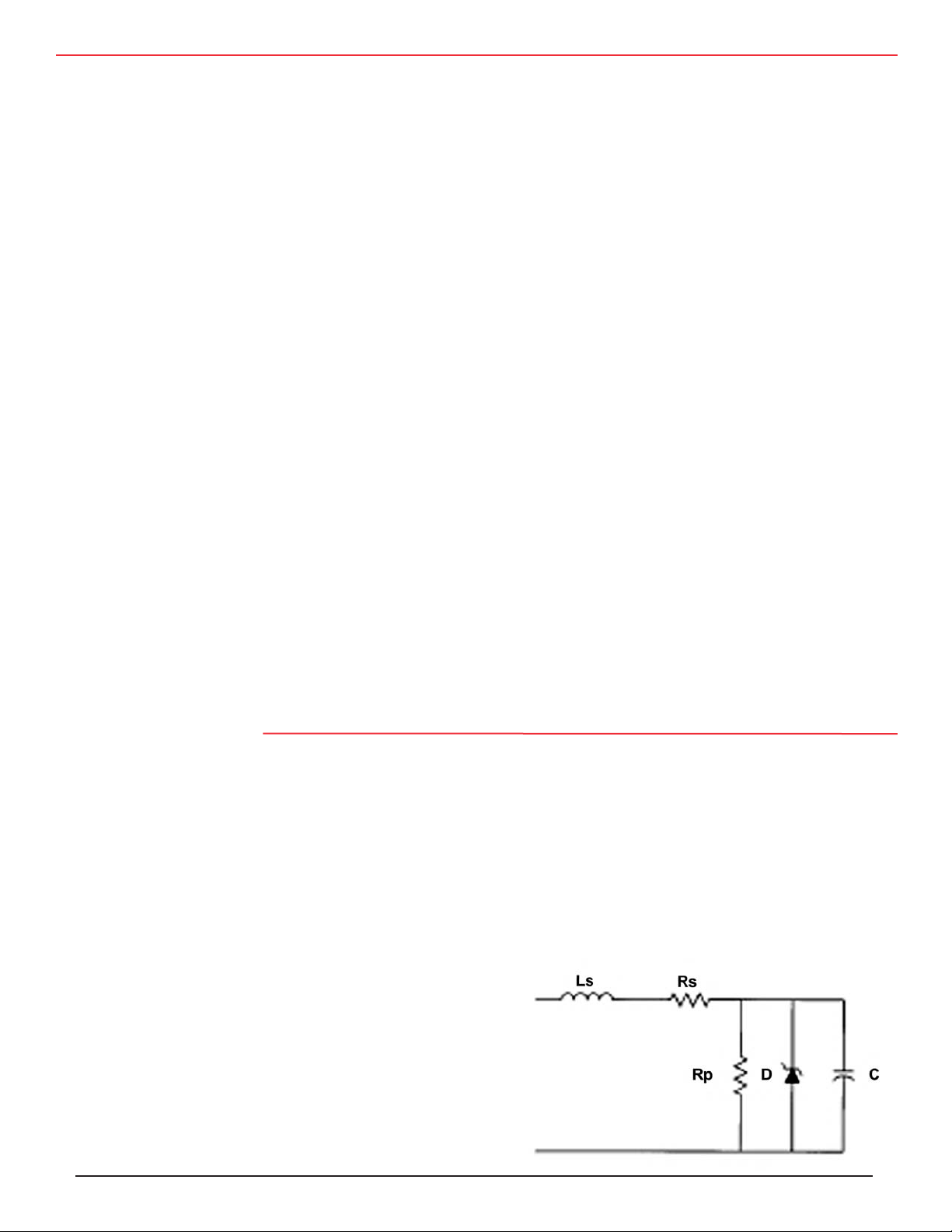
The circuit at the right models the aluminum electrolytic
capacitor’s normal operation as well as overvoltage and
reverse-voltage behavior. Capacitance C is the equivalent
capacitance and it decreases with increasing frequency.
Common values range from
CDM Cornell Dubilier • 140 Technology Place • Liberty, SC 29657 • Phone: (864)843-2277 • Fax: (864)843-3800 • www.cde.com
1 µF to 1 F, a six-decade range.
2
and d
decreases with increasing frequency and temperature. It increases with rated voltage. Typical values range from 10 m�
to 1 Ω , and Rs is inversely proportional to capacitance for a
given rated voltage.
Inductance Ls is the equivalent series inductance, and it is
relatively independent of both frequency and temperature.
Typical values range from 10 nH to 30 nH for radial-leaded
types, 20 to 50 nH for screw-terminal types, and up to 200
nH for axial-leaded types. It increases with terminal spacing.
Equivalent Circuit
Page 6

Application Guide Aluminum Electrolytic Capacitors
Resistance Rp is the equivalent parallel resistance and accounts for leakage current in the capacitor. It increases with
increasing capacitance, temperature and voltage, and it de
creases with time. Typical values are on the order of 100/C
MΩ with C in µF.
Zener diode D models overvoltage and reverse voltage be
havior. Application of overvoltage on the order of 50 V be
yond the capacitor’s surge voltage rating causes high leak
age current and a constant-voltage operating mode quite like
the reverse conduction of a zener diode.
Parameter Unit Symbol Formula Approximately
Capacitance farads (F) C
Capacitive reactance
ohms (Ω)
Current amperes (A) I C(dV/dt), Vz/Z
Dissipation factor none DF
Energy
Equivalent series resistance
joules (J) E ½CV²
ohms (Ω)
Frequency hertz (Hz) f
Impedance
ohms (Ω)
Inductance henries (H) Ls
Inductive reactance
ohms (Ω)
Loss angle degrees (°)
Phase angle degrees (°)
Power watts (W) P I²Rs, I²XcDF,(VA)(PF)
Power factor none PF
Quality factor none Q
Self-resonant frequency hertz (Hz)
Voltage
volts (V) V Vc=IXc, Vz=IZ
Volt-amperes V-A VA
Application of reverse voltage much beyond 1.5 V causes
high leakage current quite like the forward conduction of a
diode. Neither of these operating modes can be maintained
-
for long because hydrogen gas is produced by the capaci
tor, and the pressure build up will cause failure. In terms
of parameters in the next section, Rated Capacitance is C,
Dissipation Factor is 2
-
is Rs, Impedance is
-
-
and Inductance is Ls. The table below expresses these and
other parameters in terms of the equivalent-circuit model.
[(Rs)2 + (1/(2πfC) – 2πfLs)2 ]
Xc
Rs/Xc, 2πfCRs, tan δ, cot θ
Rs
Z [Rs²+ (Xc–XL)²]
X
L
δ
θ
Rs/Z, sin δ, cos θ
Xc/Rs, 1/DF, cot
ω
o
πfCRs, Equivalent Series Resistance
1⁄2
1/(2πfC)
PF
DF/(2πfC)
½
Xc
2πfLs
tan-1 DF
cot-1 DF
DF
δ, tan θ
1/PF
1/[2π(LC)½]
Z
IVz, I²Z
-
Parameters
TEMPERATURE RANGE
Operating Temperature Range
The Operating Temperature Range is the temperature range
over which the part will function, when electrified, within
the limits given in the specification. It is the range of ambient
temperatures for which the capacitor has been designed to
operate continuously. Largely the formation voltage sets the
high-temperature limit. Higher formation voltages permit
higher operating temperatures but reduce the capacitance.
The low-temperature limit is set largely by the cold resistivity of the electrolyte. The higher cold resistivity increases
the capacitor’s ESR 10 to 100 fold and reduces the available
capacitance.
CDM Cornell Dubilier • 140 Technology Place • Liberty, SC 29657 • Phone: (864)843-2277 • Fax: (864)843-3800 • www.cde.com
Typical temperature ranges are –20 °C to 55 °C, –25 °C
to 85 °C, –40 °C to 85 °C, –55 °C to 85 °C, –40 °C to
105 °C, –55 °C to 105 °C and –55 °C to 125 °C.
Storage Temperature Range
The Storage Temperature Range is the temperature range to
which the part can be subjected unbiased, and retain conformance to specified electrical limits. It is the range of ambient
temperatures over which the capacitor may be stored without
damage for short periods. For long periods of storage keep
capacitors at cool room temperatures and in an atmosphere
free of halogen gases like chlorine and fluorine that can corrode aluminum. Storage temperature ranges are from –55
°C to the upper limit of the operating-temperature ranges.
Page 7

Application Guide Aluminum Electrolytic Capacitors
CAPACITANCE
The rated capacitance is the nominal capacitance and it is
specified at 120 Hz and a temperature of 25 °C. The rated
capacitance is also the capacitance marked on the unit.
here DF is a unit-less number express in percent, test fre
quency f is
i
n Hz, capacitance C
is in µF and ESR is in
Ω.
-
Capacitance Tolerances
Capacitance tolerance is the permitted minimum and maxi
mum capacitance values expressed as the percentage decrease and increase from the rated capacitance, ΔC/C. Typical capacitance tolerances are ±20%, –10% +50%, and –10%
+75%.
Tighter tolerances are more readily available in high volt
age capacitors, e.g., above 150 V, but tolerances tighter than
±10% are generally not available. Note that tighter tolerance
parts may meet other tolerance requirements and are readily
substitutable. The capacitance varies with temperature and
frequency. This variation itself is also dependent on the rated
voltage and capacitor size.
Capacitance Measurement
For aluminum electrolytic capacitors, capacitance is mea
sured as the capacitance of the equivalent series circuit at 25
°C in a measuring bridge supplied by a 120 Hz source free of
harmonics with maximum AC signal voltage of 1 V rms and
no forward-bias voltage.
DF Measurement
The measurement of DF is carried out at +25 °C, 120 Hz,
and no voltage bias, with a maximum 1 Vac rms signal volt
age free of harmonics. The value of DF is temperature and
frequency dependent.
DF Temperature Characteristics
The dissipation factor decreases with increasing temperature.
DF declines about 50% from 25 °C to the high-temperature
limit, but increases more than 10 fold at the low temperature
limit. The DF of the better devices rated –55 °C increases
less than 5 times at –40 °C.
DF
defined in the next paragraph, varies little with tem-
lf,
perature and ESR
, also in the next paragraph, increases 10
hf
to 100 times from 25 °C to the low-temperature limit. The
increase in DF at cold temperatures is set by the ESRhf.
-
DF Frequency Characteristics
The dissipation factor varies with frequency at high frequen
cies. DF can be modeled as below:
-
-
Capacitance Temperature Characteristics
The capacitance varies with temperature. This variation it
self is dependent to a small extent on the rated voltage and
capacitor size. Capacitance increases less than 5% from 25
ºC to the high-temperature limit. For devices rated –40 °C
capacitance typically declines 20% at –40 °C for low-volt
age units and up to 40% for high-voltage units. Most of the
decline is between –20 °C and –40 °C. For devices rated
–55 °C capacitance typically declines less than 10% at –40
°C and less than 20% at –55 °C.
Capacitance Frequency Characteristics
The effective capacitance decreases as frequency increases.
Self-resonance is typically below 100 kHz depending on capacitance. At self-resonance the device is resistive and be
yond it is inductive. The termination style (i.e., axial, radial,
screw-terminal) will influence the inductive characteristics.
Small radial-leaded capacitors have inductance of less than
20 nH. Larger capacitors have more inductance according to
terminal spacing.
DISSIPATION FACTOR (DF)
Dissipation factor is the measurement of the tangent of the
loss angle (tan
δ) expressed as a percentage. It is also the ratio
of the ESR to the capacitive reactance and is thus related to
ESR by this equation:
DF = 2πfC(ESR)/10,000
DF = DFlf + 2πfC(ESRhf)/10,000
Where DF is a the total dissipation factor in percent, DF
the low-frequency dissipation factor in percent, ESR
high-frequency ESR in
C is the capacitance in µF at the test frequency. DF
-
Ω, f is the test frequency in Hz and
hf
results
lf
from the power lost by the applied electric field in orienting he molecules of the aluminum oxide dielectric. ESR
results from the resistive losses in the foils, connections and
the electrolyte/separator pad. The electrolyte/ separator pad
resistance usually dominates and its resistance varies little
with frequency. DF
ranges from about 1.5% to 3%. ESRhf
lf
ranges from 0.002 to 10 and decreases with temperature.
The DF equation above shows that DF is constant for low fre
quencies and crosses over to increasing-DF, constant ESR, at
a crossover frequency inversely proportional to capacitance.
Since high-capacitance capacitors have low crossover fre
quencies, DF increases more with increasing frequency than
for lower-capacitance capacitors.
EQUIVALENT SERIES RESISTANCE (ESR)
The equivalent series resistance (ESR) is a single resistance
representing all of the ohmic losses of the capacitor and con
nected in series with the capacitance.
is
lf
is the
hf
-
-
-
CDM Cornell Dubilier • 140 Technology Place • Liberty, SC 29657 • Phone: (864)843-2277 • Fax: (864)843-3800 • www.cde.com
Page 8
Application Guide Aluminum Electrolytic Capacitors
ESR Measurement
For aluminum electrolytic capacitors, ESR is measured as
the resistance of the equivalent series circuit at 25 °C in a
measuring bridge supplied by a 120 Hz source free of har
monics with maximum AC signal voltage of 1 V rms and no
forward-bias voltage.
ESR Temperature Characteristics
The ESR declines with increasing temperature. ESR declines
about 35% to 50% from 25 °C to the high-temperature limit,
but increases more than 10 fold at the low-temperature limit.
The ESR of devices rated –20 °C or –40 °C can increase
more than 100 times at –40 °C.
DFlf varies little with temperature and ESRhf increases 10
to 100 times from 25 °C to the low-temperature limit. The
increase in ESR at cold temperatures is set by the ESRhf.
ESR Frequency Characteristics
Like DF, the ESR varies with frequency. Rewriting the DF
equation above, ESR can be modeled as below:
ESR = 10,000(DFlf)/(2πfC) + ESR
hf
For low-temperature impedance measurement, place the ca
pacitors in a chamber set to the low-temperature limit ±2
°C. Measure impedance at 120 ±5 Hz using any suitable
method providing an accuracy of ±2½%. After temperature
stabilization, make the measurements quickly using as small
as practical an AC measuring voltage in order that it will not
cause heating of the capacitors. Assure that the capacitors
have reached thermal stability by demonstrating that two
successive measurements taken at 15 minute intervals show
no change.
Z Temperature Characteristics
Impedance typically decreases less than 5% from 25 °C to
the high-temperature limit but increases up to 10 times to the
low-temperature limit.
Z Frequency Characteristics
The frequency characteristics of impedance are dictated by
the contributions from capacitive reactance (1/(
ductive reactance (2
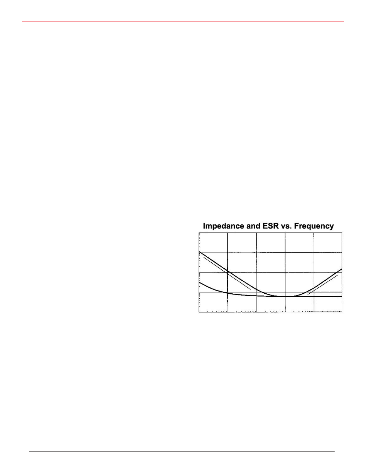
electrolyte. A typical impedance-versus-frequency curve is
shown below. The low point is at the self-resonant frequen
cy, and the impedance is equal to the ESR at that frequency.
πfLs) and from resistive losses in the
2πfC)), in-
-
-
Expressing the ideas in ESR terms, at low frequencies the
ESR declines steadily with increasing frequency and crosses
over to constant ESR at a frequency inversely proportional
to capacitance. This crossover is typically below 10 kHz.
The ESR of high-capacitance capacitors changes little with
increasing frequency because high-capacitance causes them
to have low crossover frequencies. The ESR
0.002 for large, screw-terminal capacitors to 10 for minia
ture devices.
IMPEDANCE Z
For aluminum electrolytic capacitors impedance is actually
impedance magnitude. It is the ratio of voltage to current at a
given frequency and is related to the capacitor’s capacitance,
ESR and series inductance as follows:
Z = [(ESR)² + (1/(2πfC) – 2πfLs)²]½
ranges from
hf
100
10
Z
Xe
1
-
ESR XL
0.1
Impedance/ESR Ω
0.01
10 100 1000 10000 100000 1000000
Impedance vs. Frequency
DC LEAKAGE CURRENT (DCL)
DC Leakage Current is the DC current flowing through the
Where Z is impedance in , ESR is equivalent series resis
tance in, f is frequency in Hz, C is capacitance in F and Ls is
equivalent series inductance in H.
(Z) Measurement
For aluminum electrolytic capacitors, Z is measured as the
impedance magnitude of the equivalent series circuit at 25
°C in a measuring bridge supplied by a variable frequency
source capable of delivering an AC signal voltage of 1 Vrms
free of harmonics from 10 Hz to 100 kHz. Impedance mea
surements are mostly for typical performance curves and for
low-temperature limit measurements.
CDM Cornell Dubilier • 140 Technology Place • Liberty, SC 29657 • Phone: (864)843-2277 • Fax: (864)843-3800 • www.cde.com
capacitor with the rated voltage applied. The value of leak
-
age current depends on the voltage applied, the charging
period and capacitor temperature.
DCL Method of Measurement
Measure leakage current at 25 °C with the rated voltage
applied through a protective resistance of 1000 Ω in series
with the capacitor in the measuring circuit. Five minutes
after the application of voltage, the leakage current is not
-
to exceed the maximum value indicated in the specifica
tion.
-
-
Page 9
Application Guide Aluminum Electrolytic Capacitors
DC Leakage versus Temperature, 8600 µF 100 V
DC Leakage versus Temperature, 4700 µF 450 V
0.01
1
0.1
DC Leakage (mA)
25 35 45 55 65 75 85
25 35 45 55 65 75 85
0.01
0.1
1
DC Leakage (mA)
Temperature (ºC)
Temperature (ºC)
100% V
100% V
90% V
90% V
DC Leakage versus Voltage, 4700 µF 450 V
DC Leakage versus Voltage, 8600
µF 100 V
0.01
0.1
1
10
100
DC Leakage (mA)
90 95 100 105 110 115 120
90 95 100 105 110 115 120
0.01
0.1
1
10
85 ºC
85 ºC
25 ºC
25 ºC
Percent Rated Voltage
Percent Rated Voltage
DC Leakage (mA)
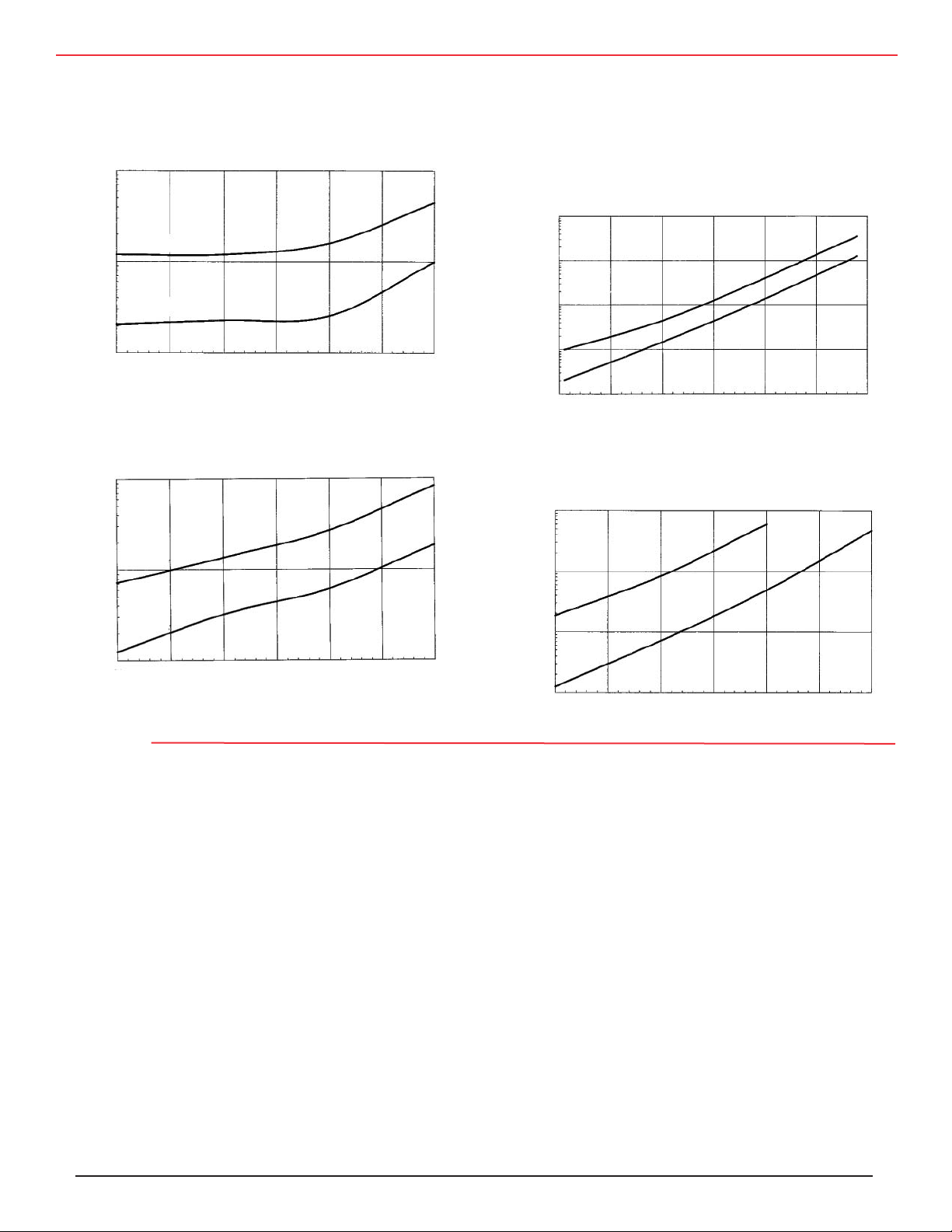
DCL Temperature Characteristics
Typical characteristic curves are shown below:
DCL Voltage Characteristics
The leakage current value drops rapidly as the applied voltage decreases below the capacitor’s rated
voltage. The effect of voltage derating on the leak
age current is shown below:
-
Voltage
Rated DC Voltage
Rated DC voltage is the voltage marked on the capacitor, and it is the maximum peak voltage including ripple
voltage that may be applied continuously between the
terminals and over the rated temperature range. Higher
rated voltage capacitors may be substituted for lower
rated voltage capacitors as long as case size, DF, and
ESR ratings are also compatible.
Rated Surge Voltage
Rated surge voltage is the maximum DC overvoltage to
which the capacitor may be subjected at 25 °C for short
periods not exceeding approximately 30 s at infrequent
intervals of not less than 5 min.
Surge Voltage Measurement
Subject the capacitors to their rated surge voltage at
normal room temperature and through a 1000 Ω ±10%
resistor (except for capacitances of 2500 µF and up, use
a 2,500,000/C Ω ±10% resistor where C is the capaci
tance in µF). Cycle the voltage ½ minute on followed
by 4½ minutes off during which each capacitor is discharged through the charging resistor or equal resistor. Repeat the cycles for 120 h. Post test requirements
are for DCL, ESR and DF to meet initial requirements
and for there to be no evidence of mechanical damage or electrolyte leakage. Electrolyte residue with no
droplets or visible flow is permitted.
-
CDM Cornell Dubilier • 140 Technology Place • Liberty, SC 29657 • Phone: (864)843-2277 • Fax: (864)843-3800 • www.cde.com
Page 10

Application Guide Aluminum Electrolytic Capacitors
Reverse Voltage
Aluminum electrolytic capacitors are polarized and must be
connected in the correct polarity. They can withstand reverse
voltages up to 1.5 V. Higher reverse voltage can cause failure
by pressure build up and rupture of the capacitor’s safety
vent structure. Non-polar and semi-polar devices are available that can withstand reverse voltage.
Transient Overvoltage
Aluminum electrolytic capacitors can generally withstand
extreme overvoltage transients of limited energy.
Ripple Current
Ripple Current
Ripple current is the AC current flowing in the capacitor. It’s
called ripple current because the associated AC voltage rides
like ripple on water on the capacitor’s DC bias voltage. The
ripple current heats the capacitor and the maximum permit
ted ripple current is set by how much can be permitted and
still meet the capacitor’s load life specification. Too much
temperature rise will cause the capacitor to exceed its maximum permitted core temperature and fail quickly, but opera
tion close to the maximum permitted core temperature dramatically shortens expected life. The load life specifications
for aluminum electrolytic capacitors operating at maximum
permitted core temperature are typically 1000 to 15,000
hours. That’s 6 weeks to 1.7 years.
Ripple Current Specification
Ripple current ratings are specified for an expected temper
ature rise at rated temperature. Commonly capacitor types
rated 85 °C permit a temperature rise of 10 °C and have a
maximum permitted core temperature of 95 °C. Often types
rated 105 °C permit a temperature rise of 5 °C and have a
maximum core temperature of 110 °C. Actual maximum
permitted core temperatures vary by type and manufacturer.
Ripple current ratings usually assume that the capacitor is
convection cooled and that the entire can is in contact with
air. A convection coefficient of 0.006 W/°C/in² predicts the
temperature rise from air to the case, and the core tempera
ture is assumed to be the same as the case temperature. The
power dissipated is the ripple current squared times the ESR.
Often the 25 °C, 120 Hz maximum ESR is used, but since
ESR decreases at elevated temperatures, less than maximum
ESR may be used to calculate power dissipated.
Here’s an example. Suppose you wanted the ripple-current
rating for a 4700 µF, 450 V capacitor in a 3 inch (76 mm)
diameter and 5⅝ inches (143 mm) long can and the
Application of overvoltage more than about 50 V beyond the
capacitor’s surge voltage rating causes high leakage current
and a constant-voltage operating mode quite like the reverse
conduction of a zener diode. The capacitor may fail short
if the electrolyte cannot take the voltage stress, but even if
it can, this operating mode cannot be maintained for long
because hydrogen gas is produced by the capacitor, and the
pressure build up will cause failure. However, special de
signs are available that use the overvoltage, zener-clamping
affect to successfully protect equipment from overvoltage
transients such as lightning strikes.
maximum ESR at 25 °C and 120 Hz is 30 mΩ. The can area
– not including the terminal end – is 60.1 in² (388 cm²). The
thermal conductance is (0.006)(60.1) = 0.36 W/°C. For a 10
°C temperature rise the case may dissipate 3.6 W. So the per
mitted ripple current with an ESR of 30 mΩ is 11 A. If you
assume that the ESR would decrease 35% by 85 °C, then the
maximum ripple current can be 13.6 A.
With large-can capacitors like the one in this example ne
glecting the temperature rise from the case to the core can
seriously overstate the ripple current capability. With some
constructions the core is 3 to 5 °C per watt of ripple power
hotter than the case. So the total temperature rise would be
more than double the intended 10 °C with rated ripple current and maximum ESR. It is generally safe to assume that
the core temperature is the same as the case temperature for
capacitors smaller than 25 mm diameter. For larger cases
with high ripple current, verify the temperature rise by
requesting samples with thermocouples imbedded in the
cores.
Cornell Dubilier Thermal Pak and Rilled computergrade ca
pacitors have controlled, low thermal resistance from core
to case. You can predict temperature rise using the thermal
resistance table later in this section or by using the thermalresistance/expected-life model available on the website,
http://www.cde.com
-
Ripple Current Temperature Characteristics
Rated ripple current can be increased for operating tem
peratures less than rated temperature. Multipliers are shown
in the specifications. Generally the multipliers are derived
based on maximum core temperature (Tc), rated temperature
(Tr) and ambient temperature (Ta) as
Ripple Temperature Multiplier = [(Tc – Ta)/(Tc – Tr)]
Counting on multipliers for temperatures below 60 °C and
-
-
-
-
-
1⁄2
CDM Cornell Dubilier • 140 Technology Place • Liberty, SC 29657 • Phone: (864)843-2277 • Fax: (864)843-3800 • www.cde.com
Page 11

Application Guide Aluminum Electrolytic Capacitors
for more than 1½ times rated ripple current is risky. High
ripple currents can cause shorter operating lives than expected because as the capacitor ages its ESR increases and
causes more heating for the same ripple current. This accelerates wearout.
Ripple Current Frequency Characteristics
Rated ripple current can be adjusted for operation at
frequencies other than 120 Hz. Multipliers are shown in the
specifications. Generally the multipliers are derived based
on expected ESR change with frequency; however, as dis
cussed above, ESR is a complex function of temperature,
capacitance and rated voltage as well as frequency. So it is
difficult to create ripple-frequency multiplier tables that ac
curately model the frequency dependence. For high-ripple
current applications verify ESR at frequencies of interest
and calculate total power dissipated.
Inductance
Inductance is the equivalent series inductance, and it is
relatively independent of both frequency and temperature.
Typical values range from 2 to 8 nH for SMT types, 10 nH
to 30 nH for radial-leaded types, 20 to 50 nH for screw terminal types, and up to 200 nH for axial-leaded types. These
low values are achieved by tab location and intrinsic, low
inductance of the dielectric contact geometry. The capaci
tor element has typical inductance of less than 2 nH.
Low-Temperature Impedance
Low-temperature impedance is the capacitor’s 120 Hz im
pedance measured at the low-temperature limit. It is usually
expressed as a multiple of the device’s 25 °C impedance.
For low-temperature impedance measurement, place the
capacitors in a chamber set to the low-temperature limit ±2
°C. Measure impedance at 120 ±5 Hz using any suitable
method providing an accuracy of ±2
ture stabilization, make the measurements quickly using as
small as practical an AC measuring voltage in order that
it will not cause heating of the capacitors. Assure that the
capacitors have reached thermal stability by demonstrating
that two successive measurements taken at 15 minute intervals show no change.
Self-resonant Frequency
The self-resonant frequency is the frequency at which the
capacitive reactance (1/(2
actance (2πfLs). Because the capacitive reactance is 180
degrees out of phase with the inductive reactance, the two
reactances subtract out, and the remaining impedance is
purely resistive and is equal to the ESR at that frequency.
πfC)) equals the inductive re-
½%. After tempera-
Above self resonance the device is inductive. In aluminum
electrolytic capacitors the self-resonant frequency typically
occurs at less than 100 kHz. The self-resonant frequency is
equal to 1/[2
expected based on 120 Hz capacitance because capacitance
decreases with increasing frequency. Resonant frequency
also increases with temperature from increasing capaci
tance.
Dielectric Absorption
-
Dielectric absorption may be observed as the reappearance
of a voltage across a capacitor after the terminals have been
shorted for a brief period and the short removed. This char
-
acteristic is important in RC timing circuits, triggering systems and phase shift networks. For aluminum electrolytic
capacitors dielectric absorption will allow up to 10% recovery of the charging voltage between 100 s and 1000 s at 25
°C, and is more pronounced at higher temperatures. Maximum dielectric absorption can be obtained by charging ca
pacitors for 1 hour at rated voltage and discharging through
a dead short for 1 minute. Subsequent measurements over
time can be made with a high impedance micrometer.
With high-voltage aluminum electrolytic capacitors rebound
voltages of 40 to 50 V are possible. While such voltages are
-
not a safety hazard, they can certainly create a frightening
distraction if the terminals are shorted by a tool during in
stallation. Conductive tape and wire shorting straps can be
supplied for the faint of heart. The tradeoff is extra cost and
-
the labor to remove them.
Insulation and Grounding
With electrolyte aluminum electrolytic capacitors the alu
minum cases connect to the negative terminals by contact
with electrolyte. The resulting isolation resistance may vary
from a few ohms to a few thousand ohms. For axial-leaded
capacitors and flatpacks the case is connected to the negative lead. If objects contacting the cases are to be at a potential other than the negative terminals, use capacitors with
insulating sleeves.
The plastic insulation can withstand 3000 Vdc or 2500 Vac,
60 Hz for 1 minute applied between the case and ¼ inch
wide metal foil placed around the sleeve. For stud-mount
ing, apply the voltage between the chassis and the case, and
mount the capacitor with an approved nylon nut and clearance hole.
Insulation resistance is no less than 100 M
utes electrification with 100 volts applied between the foil
and the capacitor case. In applications with vibration abrasion additional insulation may be needed.
π(LC)½ ]. It occurs at a frequency higher than
Ω after 2 min-
-
-
-
-
-
-
CDM Cornell Dubilier • 140 Technology Place • Liberty, SC 29657 • Phone: (864)843-2277 • Fax: (864)843-3800 • www.cde.com
Page 12

Application Guide Aluminum Electrolytic Capacitors
External Pressure
Not relevant for capacitors with solid electrolyte. Aluminum electrolytic capacitors can operate to 80,000 feet and
pressures as low as 3 kPa. Maximum air pressure depends
on the size and style of the capacitor. Exceeding the maxi
mum value can damage the capacitor by crushing the case,
opening the pressure-relief vent or causing a short circuit.
Vibration
Aluminum electrolytic capacitors can generally withstand
10 g vibration forces. Rilled capacitors can withstand 15 g.
Limits are shown in the specifications. Adjust the procedure
below as required by the individual type specifications.
To test vibration resistance, clamp the capacitors to a vibrat
ing platform and subject them to a simple harmonic motion
having a maximum peak-to-peak amplitude of 0.06 inches
and a maximum acceleration of 10 g or 15 g as specified.
Vary the frequency of vibration linearly between 10 and 55
Hz. Traverse the entire frequency range in 1 minute. Un
less specified otherwise, vibrate the capacitors for 1½ hours
with the direction of motion being parallel to the axis of the
capacitor, then place the capacitors so that the direction of
motion is perpendicular to the axis and continue vibration
for 1½ hours. During the last ½ hour of test connect the ca
pacitor to a bridge and observe for a 3-minute period.
There will be no evidence of loosening of the capacitor el
ement within the container when shaken by hand following the test. Also there will be no indication of intermittent
contact, open or shorting during the 3-minute observation
period.
Pressure-Relief Vent
During operation of an aluminum electrolytic capacitor with
electrolyte, gas pressure normally increases. This gas is
mostly hydrogen and excess pressure is avoided by perme
ation of the gas through the capacitor’s seal. But in cases
like application of overvoltage, reverse voltage, AC voltage
or capacitor failure, excess pressure can cause the capacitor
to explode. To avoid the risk of explosion aluminum electrolytic capacitors are usually equipped with pressure-relief
vent structures. These safety vents are intended to rupture
and release the gas pressure. After rupture the capacitor has
limited life because it loses electrolyte and dries out.
Be careful not to interfere with the operation of the vent,
for instance by mounting measures such as clamps, glue or
potting compounds. In the case of large capacitors with the
capacitor elements secured by thermoplastic potting, don’t
mount them with the safety vents down as the potting may
flow when the capacitors overheat and block the vents.
functioning pressure relief device may not react in time. This
could be from extreme overload or ignition of gas inside the
capacitor through sparking caused by breakdown. Protect
personnel from possible rupture of highenergy capacitors
with shielding, and be sure to use substantial shielding when
testing the pressure-relief vent. Examples of appropriate
shielding for testing are 1/4-inch thick steel or 1/2-inch thick
polycarbonate enclosures with one end open to redirect the
explosion rather than contain it.
Test the capacitor’s pressure-relief capability by applying
voltage or current using one of the following three methods.
A. Subject the capacitor to AC current according to the rated
capacitance as below:
-
Rated Capacitance Test Current
(µF) 60 Hz (Aac)
Up to 3,000 1 to 100
3,000 to 20,000 85 to 150
Above 20,000 100 to 175
-
B. For a capacitor rated 150 Vdc and above, apply 110 to
125 Vac, 60 Hz through a 5 Ω ±10% series, current-limiting
resistor.
C. Subject the capacitor to reverse polarity, DC voltage suf
ficient to allow a current from 1 to 10 A to flow.
The excess internal pressure will be relieved without violent
expulsion of the capacitor element or cover or ignition of
surrounding material. To demonstrate non-ignition, wrap the
case loosely with two layers of cheese cloth which must not
ignite during test. A short or open circuit is not a failure of
the test.
Contact with Electrolyte
The electrolyte in non-solid electrolyte capacitors is a biode
gradable liquid based on a stable solvent with a high boiling
point as the main ingredient. Common solvents are ethylene
glycol (EG), dimethylformamide (DMF) and gammabutyrolactone (GBL). The electrolyte includes an acid base system
and other chemicals. The electrolyte is chemically neutral
and contains no PCBs or halogenated compounds. It has
low toxicity but avoid contact with the skin or eyes and avoid
prolonged inhalation. A Material Safety Data Sheet is available upon request.
Immediately treat contact with electrolyte by rinsing ex
posed area with water. If electrolyte contacts eyes, flush for
10 minutes with running water. Seek medical attention if any
symptoms persist. Avoid inhalation of electrolyte vapors
or dust particles. If vapors are present, ventilate the room.
Smoke from burning electrolyte is irritating but does not
-
-
-
CDM Cornell Dubilier • 140 Technology Place • Liberty, SC 29657 • Phone: (864)843-2277 • Fax: (864)843-3800 • www.cde.com
Page 13

Application Guide Aluminum Electrolytic Capacitors
(click to go to Ohmite resistors)
obtain dioxins or similar toxic substances. If electrolyte gets
on clothing, wash it off with water.
Charge-Discharge
Frequent, rapid charge and discharge of aluminum electro
lytic capacitors not designed for such service can damage
the capacitors by overheating and overpressure or break
down with consequent failure by open or short circuit. For
charge-discharge applications use capacitors designed for
that use, and don’t exceed the manufacturer’s recommended
discharge rate.
Polarity – Reverse Voltage
Check the polarity of each capacitor both in circuit design
and in mounting. Polarity is marked on the capacitor. While
the capacitors can withstand continuous application of 1.5 V
reverse voltage, exceeding that can damage the capacitor
Circuit Configurations
by overheating, overpressure, and dielectric breakdown. This
can result in associated open-circuit or short-circuit failures
and rupture of the capacitor’s pressure-relief vent.
Flammability
Aluminum electrolytic capacitors contain materials which
can catch fire and support combustion when contacted by
flames. Flammable parts include plastic parts, insulating
sleeves, paper, and the electrolytes. Most capacitors will
pass the needle-flame test requirements of UL 94V-O and
not support combustion to the requirements of Category B
or C.
In rare cases the capacitor may self-ignite from heavy over
load or capacitor defect. Hydrogen in the capacitor can ignite if sparking occurs during capacitor failure. In critical
applications such as mining applications consider providing
fire-resistant shields.
-
PARALLEL
Capacitors may be connected in parallel for increased capaci
tance and ripple-current capability.
Bus Structure
When connecting capacitors in parallel, design the connecting bus with these features in mind. Minimum series
inductance requires a laminated bus or strip-line structure.
For example, have one plane of the circuit board as the plus
connection and another plane as the minus connection to all
capacitors. Path resistance to each capacitor should be equal
to assure equal current sharing. While ripple current divides
among the capacitors in proportion to capacitance values for
low-frequency ripple, high-frequency ripple current divides
in proportion to ESR values and path resistance.
Fusing
In order to fuse the individual capacitors, include a slowstart
circuit at equipment turn-on, and fuse each capacitor at twice
its expected, maximum ripple current. The slow-start circuit
can be a resistor in series with the capacitors that is shorted
after initial charging.
SERIES
Capacitors may be connected in series for increased voltage
withstanding.
Voltage Sharing
During charging the voltage on each of the capacitors con
nected in series is proportional to the inverse of the actual
capacitance, but upon reaching final voltage, the voltage on
each capacitor is proportional to the capacitor’s leakage re-
sistance. Of course in a series string all leakage currents are
-
the same, and the capacitors with a propensity for higher
leakage current will get less voltage. Since leakage current
increaseswith applied voltage, less voltage results in higher
leakage resistance, and the voltages tend to equalize. Tests
of high voltage bus capacitors in series pairs connected to
supply voltages 180% of the rated voltage showed good voltage sharing over the full temperature range, and no capacitor’s voltage was ever higher than its rated voltage. Voltage
sharing is not as good with long-life capacitor types like the
550C because the formation voltage is higher, and dc leakage current does not increse as much with applied voltage.
Balancing Resistors
The difference in leakage currents for two capacitors in se
ries at rated temperature can be estimated as 0.0015CVb in
µA where C is rated capacitance in µF and Vb is the voltage
across the two capacitors in Vdc. Using this approximation,
select a value of balancing resistance for each capacitor us
ing this formula:
R = (2Vr – Vb)/(0.0015CVr)
Where R is the balancing resistance in MΩ, Vr is the maximum voltage you want on either capacitor and Vb is the
maximum bus voltage across the two capacitors.
For three or more capacitors in series use the following equa
tion where n is the number of capacitors in series:
-
R = (Vr – Vb/n)/(0.00075CVr)
-
-
-
CDM Cornell Dubilier • 140 Technology Place • Liberty, SC 29657 • Phone: (864)843-2277 • Fax: (864)843-3800 • www.cde.com
Page 14
Application Guide Aluminum Electrolytic Capacitors
PARALLEL/SERIES
Capacitors connected as shown below with a common
connection between multiple series combinations have
these considerations.
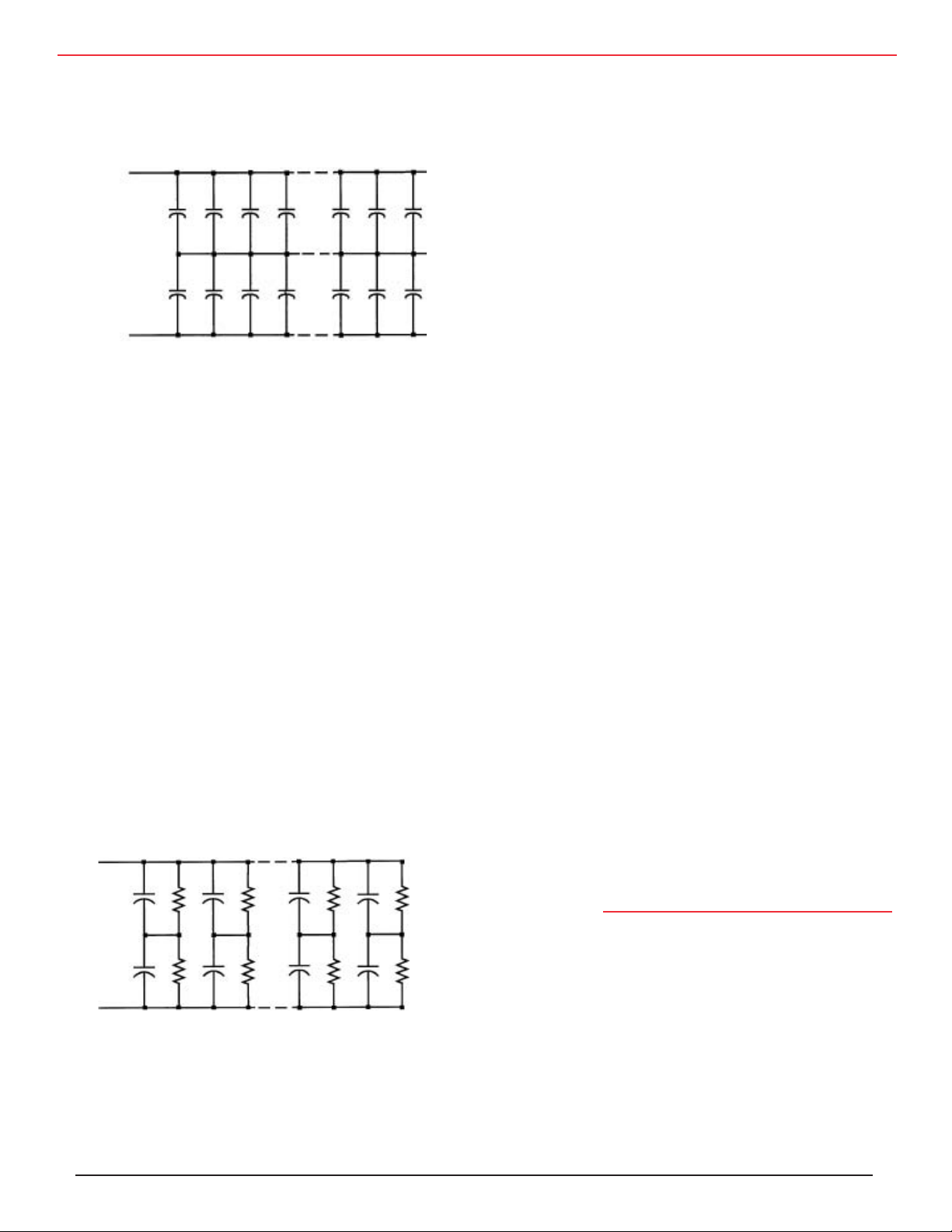
Parallel-series array with common center connection
Advantages: As the number of capacitors in parallel increases the capacitance at the top tends to equal the ca
pacitance at the bottom. This improves voltage balance
during transients. Also the leakage current at the top
tends to equal the leakage current at the bottom, so volt
age balance improves during steady-state conditions.
Finally, only two balancing resistors need be consid
ered, and the top and bottom may be so well matched as
to eliminate the need for balancing resistors.
Disadvantages: With balancing resistors the construction is more complex; many resistors need to be fitted,
and the additional resistors cost more.
NON-POLAR
If two, same-value, aluminum electrolytic capacitors
are connected in series, back-to-back with the positive terminals or the negative terminals connected, the
resulting single capacitor is a non-polar capacitor with
half the capacitance to either of the original pair. The
two capacitors rectify the applied voltage and act as if
they had been bypassed by diodes. When voltage is applied, the correct-polarity capacitor gets the full volt
age.
In non-polar aluminum electrolytic capacitors and
motorstart aluminum electrolytic capacitors a second
anode foil substitutes for the cathode foil to achieve a
non-polar capacitor in a single case. While non-polar
aluminum electrolytics are available for momentary-
duty AC applications like motor starting and voltage-
reversing applications, the high DF of aluminum elec
trolytic capacitors – from 2% to 150% – causes excess
heating and short life in most AC applications.
-
-
Disadvantage: If one capacitor fails short, the other half
of the bank gets the entire bus voltage, so other capaci
tors will fail too. Thus one capacitor failure can cause
failure of the entire bank unless the shorted capacitor is
blown open.
SERIES/PARALLEL
Capacitors connected as shown below with multiple se
ries combinations in parallel have these considerations.
This configuration is the clear choice when balancing
resistors are not used.
MOTOR START
Aluminum electrolytic, motor-start capacitors are non-
polar and designed for intermittent operation in starting
single phase induction motors or for other brief AC ap
plications such as motor-run capacitors in electric door
openers.
Aluminum electrolytic capacitors are quite reliable
largely because of their effective, self-healing mecha
nism. While wearout is the most common failure mode,
most such failures are gradual conversions to open circuits as the units become more and more resistive.
Reliability
FAILURE MODES
Early-Life Failures
Early-life failures, infant mortals, are mostly short-cir
Series-parallel array, no center connection
Advantages: If one capacitor fails short then the capacitor in series with it also fails, but other capacitors
in the bank are unaffected. If balancing resistors are
not used, high leakage current of one capacitor affects
only a single pair of capacitors. The independent, series pairs permit fusing.
CDM Cornell Dubilier • 140 Technology Place • Liberty, SC 29657 • Phone: (864)843-2277 • Fax: (864)843-3800 • www.cde.com
cuit failures from weaknesses in the aluminum oxide
dielectric. Incidence can be reduced with extended aging or burn-in.
Random Failure Rate
The following formula accurately fits failure rates for
-
-
-
Page 15
Application Guide Aluminum Electrolytic Capacitors
Cornell Dubilier aluminum electrolytic capacitors
reported on billions of unit hours of field life data in large
volume applications with multiple levels of voltage and
temperature stress.
diction increase
∆Ta 50% for screw-terminal computer-
grade capacitors and 20% for snap-in capacitors before
calculating life.
λ = 400,000NVa³C½2
(Ta-Tm)/10
⁄(L
bVr
²)
life; however, values for Mv, Lb, and Tm vary both by
capacitor type and by manufacturer. For case diameters
Most manufacturers use this model to predict operating
λ = random failure rate in FIT
N = number of capacitors in the array
Va = applied voltage in Vdc
C = capacitance of one capacitor in F
Ta = actual core temperature in °C
Tm = maximum permitted core temperature ºC
Lb = base life in hours at T
and V
m
r
Vr = rated voltage in Vdc
larger than 25 mm with significant ripple current, take
into account the temperature rise of the capacitor ele
ment over its case. Often Mv is neglected, and values
for the other variables change by case size. Typical values for Lb are 1000 to 2000 h for miniature types, 2000
to 10,000 h for snap-in types and 2000 to 20,000 h for
large-can screw terminal types. Lb can be greater than
the rated load life because no ripple is applied and be
cause it’s typical life rather than minimum. Often Tm
is 95 °C when rated temperature is 85 °C and is 108
Wear-Out
Wear-out failures are mostly open-circuit failures from
loss of electrolyte or ESR increase from other causes.
In the case of large capacitors enduring high levels of
ripple current, the increasing ESR can cause overheat
ing and shortcircuit failures as wear-out failures.
to 110 °C when it’s 105 °C. Mv based on life tests for
Cornell Dubilier, capacitor types is
Mv = 4.3-3.3Va/Vr
where Va is applied voltage and Vr is rated voltage.
Types 400C, 401C, 420C, 450C and 4CMC are tightly
sealed and behave differently when full rated voltage
and temperature are applied. For these types when both
Operating Life
Onset of wear-out is determined mainly by the capacitor’s size and average operating temperature. Operating voltage has some effect. For capacitors operating
at moderate temperatures the operating life doubles for
each 10 °C that operating temperature is reduced. Operating life can be expressed as
Lop = MvLb2
[(Tm - Ta)/10]
Where
Lop is the expected operating life in h,
Mv is a unitless voltage multiplier for voltage de rating
Lb is the expected operating life in h for full rated
voltage and temperature,
Tm is the maximum permitted internal operating
temperature in °C, and
Ta is the actual capacitor internal operating temp erature in °C.
Since ESR increases over life, the temperature rise of
Ta over ambient (
CDM Cornell Dubilier • 140 Technology Place • Liberty, SC 29657 • Phone: (864)843-2277 • Fax: (864)843-3800 • www.cde.com
∆Ta) increases. For accurate life pre
Va/Vr > 0.9 and Ta/Tm > 0.9, the voltage multiplier is
Mv = 4.3 – 3.3Va/Vr – 1000(Ta/Tm – 0.9)
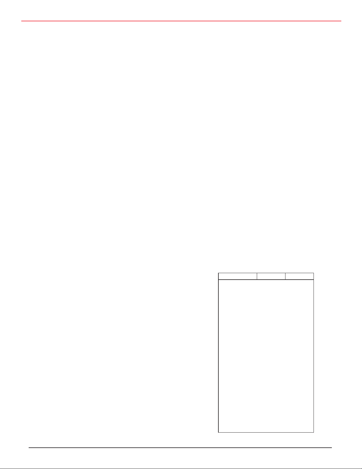
Values for expected operating life Lb and maximum
permitted core temperature Τm are
Type Lb Tm
101C 8000 h 108 ºC
300/301 6000 h 108 ºC
3186 5000 h 95 ºC
3188 8000 h 95 ºC
325 3000 h 128 ºC
330 12000 h 108 ºC
380L/LX 5000 h 95 ºC
380LQ 4000 h 95 ºC
381L/LX 5000 h 110 ºC
381LQ 4000 h 110 ºC
381LR 5000 h 115 ºC
400C 7500 h 98 ºC
401C 800 h 108 ºC
420C 12000 h 103 ºC
450C 15000 h 108 ºC
4CMC 5000 h 95 ºC
500C 7500 h 98 ºC
520C 12000 h 103 ºC
550C 15000 h 108 ºC
DCMC 5000 h 95 ºC
MLP up to 250V
MLP 300V & up
MLS 4000 h 125 ºC
12000 h 88 ºC *
5000 h 88 ºC **
* 3000 h, 108 °C if clamped and held flat
** 1200 h, 108 °C if clamped and held flat
1.65
(Va/Vr – 0.9)
-
-
-
1.65
Page 16

Application Guide Aluminum Electrolytic Capacitors
Determining Operating Life
Determine expected operating life from the capacitor’s
expected operating temperature and voltage using the op
erating life formula. The operating temperature is the ex
pected average ambient temperature plus temperature rise
from ripple current and leakage current. Leakage-current
power is small compared
to ripple-current power and can
be neglected. Measure temperature rise from ripple current
using sample capacitors with thermocouples installed at the
core hotspot, or calculate temperature rise from dissipated
power. If you calculate the power, do so at each significant
ripple frequency and add the powers together for total pow-
er. Use the Thermal Resistance Chart in this section to
determine temperature rise. It’s equal to power multiplied
a maximum ESR at 25 °C and 120 Hz of 30 m�. Suppose
that the capacitor is used as a bus capacitor in a motordrive
inverter, and the ripple current consists of 11 A at 360 Hz and
-
6.5 A at 8000 Hz. And the average applied voltage, the bus
-
voltage, is 390 Vdc.
First, calculate the ESRs at the two frequencies. While
would use one or the other of the methods above to calculate
ESR, here we’ll use both to illustrate. If the capacitor is a
Type DCMC, the frequency multiplier from page 5 for 360
Hz is 1.13. Thus the 360 Hz ESR is 30/1.13
Or using the ESR Frequency Characteristics equation, the
360 Hz ESR is [30–39800(360-120)/360/4700] or 24.4 m
Similarly at 8000 Hz the ESRs calculate to be 19.5 and 21.6
mΩ.
by thermal resistance.
Next calculate the total power. At 360 Hz it’s (11
Calculating power at a frequency other that 120 Hz requires
knowing the ESR at the new frequency. You may infer the
ESR value from the ripple current frequency multipliers for
each type.
ESR
= ESR
f
Where ESRf = ESR at a frequency f, ESR
120/Mf
2
= ESR at 120
120
Hz and Mf = Frequency multiplier for frequency f.
Or you may calculate the new ESR using the equation in
ESR Frequency Characteristics. Using that equation to
solve for ESR
and including 3% for DFlf,
hf
or 2.9 W. At 8000 Hz it’s (6.5
total power of 3.8 W.
Then calculate the core hot-spot temperature. From the
Thermal Resistance Chart the thermal resistance for free
convection cooling is 3.07 °C/W. So the temperature rise is
(3.8)(3.07) or 14 °C. If the ambient temperature were 50 °C,
the core temperature would be 64 °C.
Now predict operating life capability using the
ing Life equation. The voltage multiplier, Mv is [4.3–
3.3(390/450)] or 1.44. Operating life is
Lop = (1.44)(5000)2
you
2
or 23.5 mΩ.
2
)(0.0244)
2
)(0.0216) or 0.9 W. That’s a
Operat-
[(95 – 64)/10]
= 61,700 h
Ω.
ESR
Where ESR is in m
3% is at the high end for DF
= ESR
f
– 39800(f – 120)/fC
120
Ω, f is in Hz and C is in µF. Although
, it fits with ESR
lf
which is a
120
maximum limit for the ESR at 120 Hz.
Besides knowing ESR at the new frequency you also need
to know the ESR at a new temperature, the expected op
erating temperature. For Cornell Dubilier capacitors with
electrolytes rated to –40 ºC this table shows representative
ratios of ESR at elevated temperatures to ESR at 25 ºC.
Rated Capacitor Temperature
Voltage 45 °C 65 °C 85 °C
Vdc Ratio to ESR at 25 °C
Up to 150 75% 68% 64%
200 to 300 79% 73% 70%
350 to 450 77% 70% 67%
500 71% 61% 54%
Here’s an illustration to unify this information. Consider
the earlier example, a 4700 µF, 450 V capacitor in a 3 inch
(76 mm) diameter and 5⅝ inches (143 mm) long can with
But if the core temperature is 64 °C, the ESR would have
decreased about 40%. The new total power would be 0.6(3.8)
or 2.3 W. The new temperature rise would be (3.07) (2.3) or 7
°C, and the core temperature would be 57 °C. Recalculating
operating life with the lower core temperature gives
-
Lop = (1.44)(5000)2
[(95 – 59)/10]
= 100,300 h
And actual ESRs are typical 70% of limit but ESR will in
crease 100% over life, so the average total power with a 50%
increase in ESR is 2.4 W. That’s a 7.4 °C rise and a 98,000
h expected life. The above example shows the iterative approach. If a higher core temperature gives the operating life
you require, you are done.
If all of the math needed to calculate operating life seems
burdensome, take cheer. You can shortcut the calculations
and consider more mounting and cooling options by visiting
our website, http://www.cde.com. There you will find Java
applets that calculate core temperature and expected life for
computergrade screw-terminal capacitors, for snap-in capac
itors and for plug-in capacitors. Plug-in capacitor types start
with the number 4, like Type 4CMC.
-
-
CDM Cornell Dubilier • 140 Technology Place • Liberty, SC 29657 • Phone: (864)843-2277 • Fax: (864)843-3800 • www.cde.com
Page 17

Application Guide Aluminum Electrolytic Capacitors
Transient Over-temperature
As said, life of aluminum electrolytic capacitors generally
doubles for each 10 °C that the core temperature is reduced.
The core is the hottest spot at about the center of the capaci
tor. However, as a capacitor heats up toward its maximum
permitted core temperature, the rules change. At tempera
tures above the maximum core temperature and by 125 °C
for most types the electrolyte can be driven from capacitor
element and the ESR can increase as much as 10 times. By
this mechanism transient over-temperature or over-current
can permanently increase the ESR and make the capacitor
unusable. Be alert to this possibility in high temperature and
high-ripple applications, and pay extra attention to system
cooling.
Load Life Test
Place the capacitors in a circulating air oven set to the upper
temperature limit, 85 °C, 105°C or 125 °C, ± 3 °C. Apply
a DC voltage and an AC ripple voltage. Adjust the AC volt
age to cause current equal to the rated ripple current to flow
and adjust the DC voltage such that the peak voltage equals
the capacitors’ rated voltage. Apply the voltage for the rated
load-life period –0 +6 h. Upon completion allow the capacitors to stabilize at 25 °C for 24 h or more. The capacitors
will meet the specified post-test limits for capacitance, ESR
and DCL.
EIA Ripple Life Test, EIA IS-479
Conduct the wear-out lifetime test per EIA Interim Standard
479. The highlights of that test are as follows: Apply rip
ple current at 120 Hz or adjust to maintain the same power
dissipation if performed at another frequency. Set DC bias
voltage equal to rated voltage minus peak applied AC voltage. Set ambient temperature to 85 ± 2 °C with airflow less
than 0.5 m/s. Periodic test interval ≤ 1000 h. Sample size
is 10 or more. Mount capacitors horizontally and spaced 25
mm or more. Choose any temperature ≤85 °C for measurements, and make all measurements at that temperature. End
of lifetime is ≤ the time when 10% or more of the sample
have
capacitance < 80% initial value or
ESR > 200% initial requirement or
DCL > initial value or
evidence mechanical damage or leakage of electrolyte. 10%
of sample may fail short or open and not be counted.
Voltage Derating
Voltage derating is expressed as the percentage that the ap
plied voltage is less than rated voltage, e.g., a 450 V capacitor operating at 400 V would have 11% voltage derating.
voltages at least 35% higher than rated voltage and with
rated temperatures of 85 °C or higher, don’t require much
voltage derating. In applications operating at less than 45 °C
no derating is needed, and with up to 75 °C, 10% is suffi
cient. For higher temperatures and with high ripple current,
15% or 20% is appropriate. Since operating life continues to
increase for further derating, military and space applications
use 30% voltage derating.
Photoflash capacitors may be used at full rated voltage at
normal room temperatures because they are designed for
such duty. Strobe capacitors benefit from at least 10% volt
age derating because their continuous operation makes them
run hot.
Cooling
Cooling Strategies
Cornell Dubilier Thermal Pak capacitors conduct heat from
the core to the bottom much more effectively than out the
sides. You can take advantage of this heat path by mounting
the capacitors directly to metal chassis. In many case sizes
this can double the permitted ripple current for the same
temperature rise.
Mounting can be by using capacitors with mounting studs
and screwing the capacitors directly to the plate or it can be
by pressing the capacitors against a plate using the inter
connecting bus structure. Cornell Dubilier furnishes silpad
inserts at the bottom of the capacitors for this application.
The silpads create smooth bottoms by eliminating the steps
at the sleeve rollovers. The thermal resistance between the
can and the underlying plate for capacitors merely sitting
on the plate is about 2.5 °C/W. This decreases to less than 1
°C/W if the capacitors are pressed in place.
An Operating Life and Temperature Calculator is available
on the Cornell Dubilier website which permits you to ex
plore cooling options and directly see the affect on operating
life. Go to http://www.cde.com
Thermal Resistance
In large-can capacitors, especially ones with potting, there
is significant temperature rise from the case to the core,
the hottest spot at the center of the capacitor. For Cornell
Dubilier Thermal Pak and Rilled computergrade capacitors
use the following thermal resistance data to determine temperature rise from power dissipated. As an illustration, consider 20 amps of ripple current at 120 Hz in a 3 x 5⅝ case
with a maximum ESR of 20 m. The hot, typical ESR would
be about half that or 10 mΩ, and the power dissipated would
be I²Rs, 20²x0.01 or 4 W.
-
-
-
-
Aluminum electrolytic capacitors made with formation
CDM Cornell Dubilier • 140 Technology Place • Liberty, SC 29657 • Phone: (864)843-2277 • Fax: (864)843-3800 • www.cde.com
Page 18
Application Guide Aluminum Electrolytic Capacitors
The Free-Convection cooling column shows a total thermal resistance of 3.07 °C/W for air on all sides and 1.02 °C/W for
the capacitor pressed against a large metal plate or chassis. With 4 W the 3.07 °C/W predicts a temperature rise of 12.3
°C, no temperature rise in the metal plate. So, consider it the best you can do. Increase the Air & Metal Chassis thermal
resistance by 0.3 °C/W if you do not use a thermal pad.
Thermal Resistance Chart for Thermal Pak Screw Terminal Aluminum Electrolytic Capacitors
Free Convection 200 lfm Airflow 500 lfm Airflow 1000 lfm Airflow
Air on Side & End Air & Metal Chasis Air on Side & End Air & Metal Chasis Air on Side & End Air & Metal Chasis Air on Side & End Air & Metal Chasis
Case Case Size Core to Core to Total Core to Core to Total Core to Core to Total Core to Core to Total Core to Core to Total Core to Core to Total Core to Core to Total Core to Core to Total
Code D X L (in) Bottom Air Bottom Air Bottom Air Bottom Air Bottom Air Bottom Air Bottom Air Bottom Air
AK 1 3/8 X 1 5/8 1.67 17.12 18.78 1.68 3.29 4.97 1.66 12.19 13.86 1.68 3.08 4.76 1.66 7.83 9.49 1.68 2.75 4.43 1.66 5.62 7.29 1.68 2.46 4.14
1 3/8 X 2 1/8 1.70 13.72 15.42 1.74 3.13 4.87 1.70 9.80 11.50 1.74 2.90 4.64 1.70 6.31 8.02 1.73 2.53 4.26 1.70 4.56 6.26 1.73 2.22 3.95
AA
AH 1 3/8 X 2 5/8 1.72 11.49 13.21 1.78 2.99 4.77 1.72 8.23 9.94 1.77 2.73 4.51 1.72 5.33 7.05 1.76 2.35 4.11 1.72 3.87 5.59 1.76 2.04 3.79
AB 1 3/8 X 3 1/8 1.72 9.91 11.63 1.80 2.86 4.66 1.71 7.12 8.83 1.79 2.59 4.38 1.71 4.64 6.35 1.78 2.19 3.97 1.71 3.39 5.11 1.77 1.88 3.65
AJ 1 3/8 X 3 5/8 1.69 8.73 10.43 1.81 2.74 4.55 1.69 6.29 7.99 1.80 2.46 4.25 1.69 4.13 5.82 1.78 2.05 3.83 1.69 3.04 4.73 1.76 1.75 3.52
AC 1 3/8 X 4 1/8 1.66 7.82 9.48 1.81 2.63 4.44 1.66 5.65 7.32 1.79 2.33 4.13 1.66 3.73 5.39 1.77 1.93 3.70 1.66 2.76 4.42 1.75 1.64 3.39
AD 1 3/8 X 4 5/8 1.62 7.09 8.71 1.80 2.52 4.32 1.62 5.14 6.76 1.78 2.22 4.00 1.62 3.41 5.03 1.75 1.82 3.57 1.62 2.54 4.16 1.72 1.54 3.27
AE 1 3/8 X 5 1/8 1.58 6.49 8.07 1.79 2.42 4.21 1.58 4.72 6.30 1.76 2.12 3.88 1.58 3.15 4.73 1.72 1.73 3.45 1.58 2.36 3.93 1.70 1.46 3.15
AF 1 3/8 X 5 5/8 1.53 5.99 7.52 1.77 2.33 4.10 1.53 4.37 5.90 1.74 2.02 3.76 1.53 2.93 4.46 1.69 1.64 3.33 1.53 2.20 3.73 1.66 1.38 3.04
1 3/4 X 2 1/8 1.03 10.40 11.43 1.05 1.90 2.96 1.03 7.43 8.46 1.05 1.79 2.84 1.03 4.79 5.83 1.05 1.61 2.66 1.03 3.46 4.50 1.05 1.45 2.49
EA
EH 1 3/4 X 2 5/8 1.06 8.77 9.83 1.09 1.84 2.93 1.06 6.28 7.34 1.09 1.71 2.80 1.06 4.08 5.14 1.09 1.51 2.60 1.06 2.97 4.03 1.08 1.35 2.43
EB 1 3/4 X 3 1/8 1.08 7.61 8.68 1.13 1.77 2.90 1.08 5.47 6.55 1.12 1.64 2.76 1.08 3.57 4.65 1.12 1.43 2.55 1.08 2.62 3.69 1.11 1.26 2.37
EJ 1 3/4 X 3 5/8 1.08 6.73 7.82 1.15 1.72 2.87 1.08 4.86 5.94 1.15 1.57 2.72 1.08 3.20 4.28 1.14 1.36 2.50 1.08 2.36 3.44 1.13 1.19 2.32
EC 1 3/4 X 4 1/8 1.08 6.06 7.13 1.17 1.66 2.83 1.08 4.39 5.47 1.16 1.51 2.67 1.08 2.91 3.99 1.15 1.29 2.44 1.08 2.16 3.24 1.14 1.13 2.27
ED 1 3/4 X 4 5/8 1.07 5.51 6.58 1.19 1.61 2.79 1.07 4.01 5.08 1.17 1.45 2.62 1.07 2.67 3.74 1.16 1.23 2.39 1.07 2.00 3.07 1.14 1.07 2.21
EE 1 3/4 X 5 1/8 1.05 5.07 6.12 1.19 1.55 2.75 1.05 3.70 4.75 1.18 1.39 2.57 1.05 2.48 3.54 1.16 1.18 2.33 1.05 1.87 2.92 1.14 1.02 2.16
EF 1 3/4 X 5 5/8 1.03 4.69 5.72 1.20 1.50 2.70 1.03 3.43 4.47 1.18 1.34 2.52 1.03 2.32 3.35 1.15 1.13 2.28 1.03 1.76 2.79 1.13 0.97 2.11
2 X 2 1/8 0.78 8.89 9.67 0.80 1.45 2.24 0.78 6.35 7.14 0.80 1.37 2.17 0.78 4.10 4.88 0.79 1.25 2.04 0.78 2.97 3.75 0.79 1.14 1.93
BA
BH 2 X 2 5/8 0.81 7.53 8.34 0.84 1.40 2.24 0.81 5.40 6.21 0.83 1.32 2.15 0.81 3.50 4.32 0.83 1.18 2.01 0.81 2.55 3.36 0.83 1.07 1.89
BB 2 X 3 1/8 0.83 6.55 7.38 0.87 1.36 2.23 0.83 4.71 5.54 0.87 1.27 2.13 0.83 3.08 3.91 0.86 1.13 1.99 0.83 2.26 3.09 0.86 1.01 1.86
BJ 2 X 3 5/8 0.84 5.82 6.66 0.90 1.32 2.22 0.84 4.20 5.04 0.89 1.22 2.11 0.84 2.77 3.61 0.88 1.07 1.96 0.84 2.05 2.89 0.88 0.95 1.83
BC 2 X 4 1/8 0.85 5.24 6.09 0.92 1.28 2.20 0.85 3.80 4.65 0.91 1.18 2.09 0.85 2.52 3.37 0.90 1.03 1.93 0.85 1.88 2.73 0.89 0.91 1.80
BD 2 X 4 5/8 0.84 4.78 5.63 0.93 1.25 2.18 0.84 3.48 4.33 0.93 1.14 2.07 0.84 2.33 3.17 0.91 0.99 1.90 0.84 1.75 2.59 0.90 0.87 1.77
BE 2 X 5 1/8 0.84 4.40 5.24 0.95 1.21 2.16 0.84 3.22 4.06 0.94 1.10 2.04 0.84 2.17 3.01 0.92 0.95 1.87 0.84 1.64 2.48 0.91 0.83 1.74
BF 2 X 5 5/8 0.83 4.09 4.92 0.96 1.18 2.14 0.83 3.00 3.83 0.94 1.06 2.01 0.83 2.03 2.86 0.93 0.91 1.84 0.83 1.55 2.38 0.91 0.80 1.71
CH 2 1/2 X 2 5/8 0.52 5.80 6.32 0.53 0.89 1.42 0.52 4.16 4.68 0.53 0.85 1.38 0.52 2.70 3.22 0.53 0.78 1.31 0.52 1.97 2.49 0.53 0.71 1.24
CB 2 1/2 X 3 1/8 0.54 5.07 5.61 0.56 0.87 1.43 0.54 3.65 4.19 0.56 0.82 1.38 0.54 2.39 2.93 0.55 0.75 1.30 0.54 1.76 2.29 0.55 0.68 1.23
CJ 2 1/2 X 3 5/8 0.55 4.53 5.08 0.58 0.85 1.43 0.55 3.27 3.82 0.58 0.80 1.38 0.55 2.16 2.71 0.58 0.72 1.30 0.55 1.60 2.15 0.57 0.65 1.23
CC 2 1/2 X 4 1/8 0.56 4.10 4.66 0.60 0.83 1.43 0.56 2.98 3.54 0.60 0.78 1.38 0.56 1.98 2.54 0.59 0.70 1.29 0.56 1.48 2.04 0.59 0.63 1.22
CD 2 1/2 X 4 5/8 0.57 3.47 4.04 0.64 0.79 1.43 0.57 2.55 3.11 0.63 0.74 1.37 0.57 1.72 2.29 0.62 0.65 1.27 0.57 1.31 1.88 0.62 0.58 1.20
CD 2 1/2 X 5 1/8 0.57 3.47 4.04 0.64 0.79 1.43 0.57 2.55 3.11 0.63 0.74 1.37 0.57 1.72 2.29 0.62 0.65 1.27 0.57 1.31 1.88 0.62 0.58 1.20
CF 2 1/2 X 5 5/8 0.57 3.23 3.80 0.65 0.78 1.43 0.57 2.38 2.95 0.64 0.72 1.36 0.57 1.62 2.19 0.63 0.63 1.26 0.57 1.24 1.81 0.62 0.56 1.19
DB 3 X 3 1/8 0.37 4.10 4.47 0.39 0.61 0.99 0.37 2.95 3.33 0.39 0.58 0.97 0.37 1.94 2.31 0.39 0.53 0.92 0.37 1.42 1.80 0.38 0.49 0.88
DJ 3 X 3 5/8 0.39 3.67 4.06 0.41 0.59 1.00 0.39 2.66 3.04 0.41 0.56 0.97 0.39 1.76 2.14 0.40 0.52 0.92 0.39 1.30 1.69 0.40 0.47 0.88
DC 3 X 4 1/8 0.40 3.34 3.73 0.43 0.58 1.01 0.40 2.43 2.82 0.42 0.55 0.97 0.40 1.62 2.02 0.42 0.50 0.92 0.40 1.21 1.61 0.42 0.46 0.88
DC 3 X 4 5/8 0.40 3.34 3.73 0.43 0.58 1.01 0.40 2.43 2.82 0.42 0.55 0.97 0.40 1.62 2.02 0.42 0.50 0.92 0.40 1.21 1.61 0.42 0.46 0.88
DE 3 X 5 1/8 0.41 2.85 3.26 0.46 0.56 1.02 0.41 2.09 2.50 0.45 0.53 0.98 0.41 1.42 1.83 0.45 0.47 0.92 0.41 1.08 1.49 0.44 0.43 0.88
DF 3 X 5 5/8 0.41 2.66 3.07 0.47 0.55 1.02 0.41 1.96 2.37 0.46 0.51 0.98 0.41 1.34 1.76 0.46 0.46 0.92 0.41 1.03 1.44 0.45 0.42 0.87
3 X 5 7/8 0.41 2.58 2.99 0.47 0.55 1.02 0.41 1.91 2.32 0.47 0.51 0.98 0.41 1.31 1.72 0.46 0.46 0.92 0.41 1.01 1.42 0.46 0.41 0.87
DP
DG 3 X 8 5/8 0.40 1.95 2.35 0.52 0.49 1.01 0.40 1.47 1.87 0.51 0.45 0.96 0.40 1.05 1.45 0.50 0.39 0.89 0.40 0.83 1.23 0.48 0.36 0.84
FC 3 1/2 X 4 1/8 0.30 2.79 3.09 0.32 0.43 0.75 0.30 2.03 2.33 0.31 0.41 0.72 0.30 1.36 1.65 0.31 0.38 0.69 0.30 1.02 1.31 0.31 0.35 0.66
FD 3 1/2 X 4 5/8 0.30 2.58 2.88 0.33 0.42 0.75 0.30 1.88 2.19 0.33 0.40 0.73 0.30 1.27 1.57 0.32 0.37 0.69 0.30 0.96 1.26 0.32 0.34 0.66
FE 3 1/2 X 5 1/8 0.31 2.40 2.71 0.34 0.42 0.76 0.31 1.76 2.07 0.34 0.39 0.73 0.31 1.20 1.51 0.34 0.36 0.70 0.31 0.91 1.22 0.33 0.33 0.67
FF 3 1/2 X 5 5/8 0.31 2.24 2.56 0.35 0.41 0.76 0.31 1.66 1.97 0.35 0.39 0.74 0.31 1.14 1.45 0.35 0.35 0.70 0.31 0.87 1.19 0.34 0.33 0.67
3 1/2 X 5 7/8 0.31 2.18 2.49 0.36 0.41 0.77 0.32 1.61 1.93 0.36 0.38 0.74 0.32 1.11 1.43 0.35 0.35 0.70 0.32 0.86 1.17 0.35 0.32 0.67
FP
FG 3 1/2 X 8 5/8 0.31 1.67 1.98 0.40 0.37 0.78 0.31 1.26 1.58 0.40 0.34 0.74 0.32 0.91 1.22 0.39 0.31 0.70 0.32 0.72 1.04 0.38 0.28 0.66
CDM Cornell Dubilier • 140 Technology Place • Liberty, SC 29657 • Phone: (864)843-2277 • Fax: (864)843-3800 • www.cde.com
Page 19
Shelf Life
Application Guide Aluminum Electrolytic Capacitors
Aluminum electrolytic capacitors stored for more than 5
to 10 years may have increased levels of DC leakage current. Check if DCL meets application requirements before
placing in service. Recondition high DCL units by applying
rated voltage through
1,000Ω resistor for 30 minutes.
To test shelf life place the capacitors in an oven set to the
shelf-life test temperature –0 +3 °C for the shelf-life test
period. Upon completion of the test stabilize the capacitors
at 25 °C for 24 h or more. Apply the rated voltage for 30
minutes, then verify the post test limits. Unless otherwise
specified the capacitance, DCL and ESR will meet initial
Shelf life test is an accelerated measure of how the capaci
requirements.
tors will withstand storage for long times especially at high
temperature.
Thermal Resistance Chart °C/W Snap-in Aluminum Electrolytic Capacitors
Free Convection 200 lfm Airflow 500 lfm Airflow 1000 lfm Airflow
Case
Case Size
Code
D x L (mm)
H01 22 x 25 7.92 22.46 30.38 7.90 13.05 20.96 7.89 8.31 16.20 7.87 5.78 13.64
H02 22 x 30 8.13 20.02 28.15 8.11 11.75 19.87 8.09 7.58 15.67 8.06 5.34 13.41
H03 22 x 35 8.33 18.15 26.48 8.31 10.78 19.08 8.28 7.05 15.32 8.24 5.04 13.28
H04 22 x 40 8.51 16.69 25.20 8.48 10.03 18.51 8.44 6.65 15.09 8.39 4.83 13.22
H05 22 x 50 8.83 14.56 23.39 8.79 8.97 17.75 8.73 6.12 14.85 8.66 4.56 13.22
J01 25 x 25 6.11 18.99 25.10 6.10 11.04 17.14 6.08 7.03 13.11 6.06 4.89 10.95
J02 25 x 30 6.32 17.01 23.33 6.30 9.99 16.29 6.28 6.44 12.72 6.25 4.54 10.79
J03 25 x 35 6.52 15.49 22.00 6.49 9.20 15.69 6.46 6.01 12.47 6.42 4.30 10.72
J04 25 x 40 6.70 14.29 20.99 6.67 8.59 15.26 6.63 5.70 12.32 6.58 4.13 10.71
J45 25 x 45 6.87 13.32 20.19 6.83 8.11 14.94 6.78 5.46 12.24 6.72 4.02 10.73
J05 25 x 50 7.03 12.54 19.57 6.98 7.73 14.71 6.92 5.27 12.20 6.85 3.93 10.78
K01 30 x 25 4.28 14.84 19.12 4.26 8.63 12.89 4.25 5.50 9.74 4.22 3.82 8.04
K02 30 x 30 4.46 13.40 17.86 4.44 7.87 12.31 4.41 5.08 9.49 4.38 3.58 7.96
K03 30 x 35 4.63 12.27 16.91 4.61 7.29 11.90 4.57 4.77 9.34 4.53 3.41 7.94
K04 30 x 40 4.80 11.38 16.18 4.77 6.84 11.61 4.73 4.54 9.26 4.67 3.29 7.96
K45 30 x 45 4.96 10.66 15.62 4.92 6.49 11.41 4.87 4.37 9.23 4.80 3.21 8.01
K05 30 x 50 5.12 10.07 15.19 5.07 6.21 11.28 5.00 4.23 9.24 4.92 3.15 8.07
A01 35 x 25 3.19 11.98 15.18 3.18 6.97 10.15 3.16 4.44 7.60 3.14 3.09 6.22
A02 35 x 30 3.35 10.89 14.24 3.33 6.40 9.73 3.31 4.13 7.43 3.28 2.91 6.18
A03 35 x 35 3.51 10.03 13.53 3.48 5.96 9.44 3.45 3.89 7.34 3.40 2.78 6.18
A04 35 x 40 3.66 9.34 13.00 3.62 5.62 9.24 3.58 3.72 7.30 3.52 2.69 6.22
A45 35 x 45 3.80 8.78 12.58 3.76 5.35 9.10 3.70 3.59 7.29 3.64 2.63 6.27
A05 35 x 50 3.94 8.32 12.26 3.89 5.13 9.02 3.82 3.49 7.31 3.74 2.59 6.33
A06 35 x 63 4.26 7.46 11.72 4.19 4.75 8.94 4.09 3.34 7.43 3.98 2.54 6.53
A08 35 x 80 4.63 6.76 11.39 4.52 4.48 9.00 4.38 3.26 7.64 4.23 2.54 6.78
A10 35 x 105 5.03 6.19 11.21 4.87 4.30 9.17 4.69 3.24 7.93 4.49 2.59 7.08
N04 40 x 40 2.90 7.84 10.74 2.87 4.71 7.58 2.82 3.12 5.94 2.77 2.25 5.02
N05 40 x 50 3.15 7.03 10.18 3.10 4.33 7.43 3.04 2.94 5.98 2.96 2.18 5.14
N06 40 x 63 3.45 6.34 9.79 3.37 4.03 7.41 3.28 2.83 6.11 3.17 2.14 5.31
N08 40 x 80 3.79 5.78 9.57 3.68 3.83 7.50 3.54 2.77 6.31 3.39 2.15 5.54
N10 40 x 105 4.18 5.33 9.51 4.02 3.70 7.71 3.83 2.77 6.60 3.63 2.19 5.83
B05 50 x 50 2.20 5.25 7.45 2.15 3.23 5.38 2.09 2.19 4.27 2.01 1.61 3.62
B06 50 x 63 2.44 4.79 7.23 2.37 3.04 5.40 2.27 2.11 4.39 2.17 1.59 3.76
B08 50 x 80 2.72 4.41 7.14 2.61 2.90 5.52 2.48 2.08 4.56 2.34 1.60 3.94
B09 50 x 92 2.90 4.24 7.14 2.76 2.86 5.62 2.60 2.09 4.69 2.44 1.61 4.06
B10 50 x 105 3.07 4.12 7.18 2.90 2.83 5.74 2.72 2.10 4.81 2.53 1.63 4.17
core to
case
case to
air total
core to
case
case to
air total
core to
case
case to
air total
core to
case
case to
air total
CDM Cornell Dubilier • 140 Technology Place • Liberty, SC 29657 • Phone: (864)843-2277 • Fax: (864)843-3800 • www.cde.com
Page 20

Application Guide Aluminum Electrolytic Capacitors
Process Considerations
SOLDERING
Preheat
Don’t exceed the maximum storage temperature during
preheating of the capacitors. If this cannot be avoided, contact the supplier first.
Temperature Duration
Strictly adhere to soldering conditions for temperature,
duration and minimum distance of solder from body. Don’t
contact the insulating sleeve or other plastic parts with a
soldering iron or molten solder. Reflow solder only SMT
types, and then only one reflow cycle. Contact the supplier
if more than one reflow is necessary.
Care after Soldering
Do not exert any mechanical force like bending, straight
ening, twisting or tilting of capacitors after soldering into a
printed circuit board.
Handling Assembled Devices
During transport and handling of assembled devices do not
misuse capacitors as a handle. Ensure that capacitors are
protected from physical damage during mounting of printed circuit boards into assemblies or during stacking.
Halogenated-Solvent Cleaning
Halogenated hydrocarbon solvents (CFC) are ozone de
pleting chemicals harmful to the environment. Such solvents can penetrate the capacitors’ seals and cause corro
sion and failure when voltage is applied, and so use them to
clean aluminum electrolytic capacitors only to the limited
conditions given by the component supplier and then only
as a last resort. Solvent-proof miniature capacitors and capacitors with epoxy endseals are available for limited use
with halogenated solvents.
Aqueous Cleaning
Water with a mild detergent may be used to clean aluminum
electrolytic capacitors. However, immediately dry the capacitors in hot air at about 85 °C for 5 or more minutes but
not hotter than the capacitors’ maximum storage temperature. Water can become trapped beneath the sleeve which
may not be dispelled by evaporation at room temperature.
Water can be trapped under the sleeve and cause hydration and discoloration of the aluminum cases, although this
does not affect capacitor operation.
Alcohol Cleaning
Alcohol solvents like isopropanol, methanol, ethanol and
propanol have no harmful affects on aluminum electrolytic
capacitors. While they are fine for cleaning, they are not
very effective in removal of commercial soldering fluxes.
-
Cleaning Precautions
The capacitor’s insulating sleeve may re-shrink or crack
if rapidly heated to above 100 °C just after cleaning. If
the solder flux contains chlorine as many active flux types
do, frequently regenerate or replace the cleaning solvent
to avoid damaging the capacitors. Cleaning solvents may
swell the insulating sleeves and affect the legibility of
marking if applied too long or with too high mechanical
forces or temperatures.
-
Potting and Gluing
Be certain that varnishing, coating, lacquering, embedding
-
or gluing near the capacitors’ seals are halogen free. And
be sure all constituent parts including base material, thin
ners, binders, reacting agents, propellants and additives are
halogen free. If the printed circuit board has been cleaned
with halogenated solvent, be sure it’s fully dry before installation of capacitors. When gluing, don’t apply glue to
the full capacitor circumference, and don’t cover the ca
pacitor’s pressure-relief vent with potting or glue.
-
-
Fumigation Warning
International shipments of electronic equipment are often in wooden crates, and these crates may be fumigated
with methyl bromide gas during shipment to control insect infestation. Also, some factories such as flourmills
are routinely fumigated with this gas. Methyl bromide can penetrate cardboard boxes, vinyl bags and other
packaging materials used to protect the equipment. Methyl bromide can also penetrate the seals of aluminum
electrolytic capacitors; cause corrosion and cause open-circuit capacitor failure after the equipment is put into
service. To protect against such failures use capacitors proven to be able to withstand fumigation or individually sealed to prevent penetration of the methyl bromide gas.
CDM Cornell Dubilier • 140 Technology Place • Liberty, SC 29657 • Phone: (864)843-2277 • Fax: (864)843-3800 • www.cde.com
Page 21
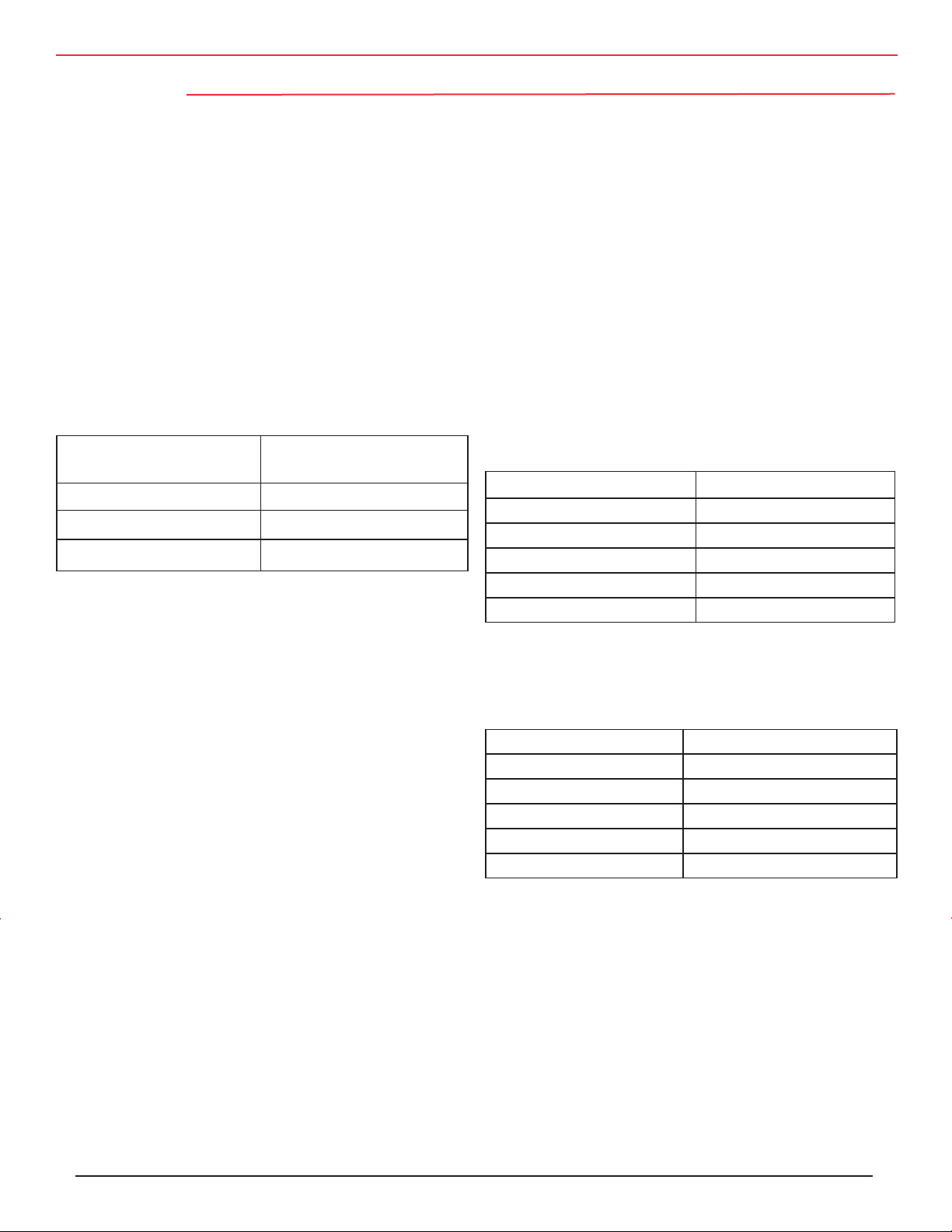
Mounting
Application Guide Aluminum Electrolytic Capacitors
Mounting Position
At lower ambient temperatures aluminum electrolytic ca
pacitors have longer operating lives; so, put the capacitors
at the coolest place on the board. Ensure that aluminum
electrolytic capacitors are away from hot components like
power resistors, power transistors or diodes and transform
ers. Adequately space components apart for cooling air to
circulate. This is especially important when high ripple
current or charge/discharge loads are applied.
Position of the Pressure-relief Device
Provide adequate clearance for proper operation of the pressure-relief devise. The following distances are a guide.
Nominal Case Space around
Diameter pressure relief device
≤ 16 mm > 2 mm
> 16 mm to < 40 mm > 3 mm
≥ 40 mm > 5 mm
Mounting the capacitors with the vent uppermost or in the
upper part of the capacitor assures that the least amount of
electrolyte will be expelled if the vent operates. Mount capacitors that include thermal-plastic potting such that the
potting cannot block the vent should the potting melt during
capacitor failure. All Cornell Dubilier aluminum electrolytic
capacitors except Types 3186 and 3188 are potting free and
may be mounted in any orientation.
Printed-circuit Board Precautions
Avoid positioning holes in places where parts of a capacitor
could be on the other side and be touched by molten solder.
Because the can and sometimes extra terminals of an alumi
num electrolytic capacitor have resistive connections to the
negative terminal through the electrolyte,
don’t locate tracks or lands under upright capaci-
tors,
don’t permit metal capacitor parts other than ac-
tive terminals to contact conductive tracks or other
components, and
Polarity Indication
-
Aluminum electrolytic capacitors are normally polarized
and require correct-polarity installation in the circuitry. To
ensure correct mounting and identification of the polarity,
put a clear + and/or – on the board layout marking. If the
-
circuit voltage can reverse polarity or is unknown, consider
using non-polar capacitors. Disadvantages are that nonpolar capacitors are larger and more expensive.
Screw-terminal Mounting Torque
Excess torque during tightening screw terminals may
affect the performance of the capacitor or damage the
terminal. The following torque settings are recommended. Be certain that at least six threads are engaged.
Terminal Recommended Torque
10–32, Low Post 25 in-lb
10–32, High Post 25 in-lb
¼ –28, Low Post 50 in-lb
¼ –28, High Post 60 in-lb
M5 Post 30 in-lb
Screw-terminal Current Rating
For normal operation the maximum recommended continuous AC currents for screw terminals are as tabulated below.
Terminal Maximum Current
10–32, Low Post 30 A rms
10–32, High Post 30 A rms
¼ –28, Low Post 50 A rms
¼ –28, High Post 50 A rms
-
M5 Post 35 A rms
The ripple current ratings may exceed the currents listed
here. Terminals can withstand these higher continuous
currents if you assure gas-tight connections to avoid
formation of aluminum oxide. Use Belleville washers
and a commercial electrical joint compound, e.g., Penetrox A, and tighten the terminals to the recommended
torque for the washers.
leave dummy pins voltage free.
CDM Cornell Dubilier • 140 Technology Place • Liberty, SC 29657 • Phone: (864)843-2277 • Fax: (864)843-3800 • www.cde.com
Page 22

Application Guide Aluminum Electrolytic Capacitors
Handling Terminals
Before handling a capacitor be sure it is sufficiently dis
charged. To avoid damaging the capacitor, don’t bend rigid
terminals, and be sure to clamp the terminals during cutting
or bending to avoid excess stress on terminations, welds and
capacitor seals.
Don’t use extra force to insert capacitors. If they cannot
be inserted easily, correct the problem. Discard capacitors
showing signs of mechanical damage.
Disposal of Capacitors
Aluminum electrolytic capacitors with non-solid electrolyte
principally include high-purity aluminum foils, capacitor paper, electrolyte, aluminum case, cover and sealing parts (phenolic, thermoplastic, rubber and phenolic board), insulating
sleeve (polypropylene, polyester or polyvinylchloride)
Mounting-stud Mounting Torque
Computergrade, screw-terminal capacitors are avail
-
able with threaded mounting studs on the can bottoms,
and nylon nuts are available for insulated mounting.
The following torque settings are recommended.
Nylon Nut Thread Recommended Torque
M8 25 in-lb
M12 75 in-lb
and, perhaps, safety-vent plugs made of synthetic rubber.
If incinerated, be certain that the temperature is more than
1200 °C. Disposal is permitted in appropriate landfills.
EPA regulations vary by state.
-
CDM Cornell Dubilier • 140 Technology Place • Liberty, SC 29657 • Phone: (864)843-2277 • Fax: (864)843-3800 • www.cde.com
 Loading...