

Mallinckrodt INOmax DS, INOmax DS IR, INOvent User Manual

IMPORTANT: This guide is provided as a convenience and for General Information only. Never
use this product without clearly and thoroughly understanding the most recent revision of the
INOmax DS, INOmax DSIR and INOvent Operation Manuals. The Operation Manual is the source
for specic, updated information regarding warnings, cautions, checklists, diagrams, and/or
instructions contained in this guide.
See set up diagram on the reverse side of this document
For assistance contact Technical Support 877-566-9466
WARNING:
1. Avoid recirculation of gases.
Undesired recirculation of gases
will occur if fresh gas ows are less
than the patient minute volume and
may result in:
• Higher NO2 levels due to the
limited ability of the carbon
dioxide absorbent to remove
NO2.
• Higher concentrations
than those set due to NO
recirculated through the
absorber.
• Reduction in O2 concentrations
because nitrogen is the
balance gas for nitric oxide
and will be present in the recirculated gases.
2. If the Injector Module was used
in the wet/humidied part of the
breathing circuit, it should be
sterilized between each patient use.
Caution:
1. Note airow direction on the
Injector Module: the ow out of the
absorber must pass through the
Injector Module in the direction of
the arrow on the module.
2. Nitrous oxide (N
2
O) will affect
the Set NO versus the measured
NO value. For a 50% N2O, 50%
O2 composition, the measured
NO value will be approximately
7% indicated less than the
same Set NO value of 100%
O2. For example, at a Set NO
of 20 ppm, measured NO will be
approximately 18 ppm.
3. Similarly, the effect of 2%
v/v isourane will result in a
high measured NO value of
approximately 3% indicated for the
same Set NO value at 100% O2.
4. Sudden changes in anesthetic
agent concentration may cause
brief transient changes in the
measured NO and NO2 values.
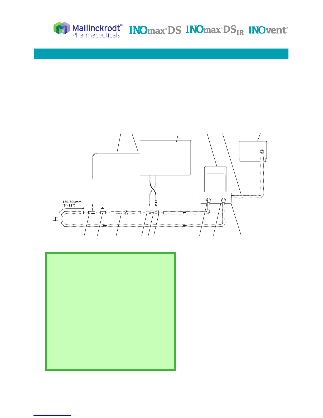
Connection to a Circle Anesthesia Ventilator System
IMPORTANT: This guide is provided as a convenience and for General Information only. Never
use this product without clearly and thoroughly understanding the most recent revision of the
INOmax DS, INOmax DS
IR
and INOvent Operation Manuals. The Operation Manual is the source
for specic, updated information regarding warnings, cautions, checklists, diagrams, and/or
instructions contained in this guide.
1. Patient wye
2. Gas sample line
3. Sample line inlet
4. INOmax DS / INOmax DSIR /
INOvent delivery system
5. Bellows assembly
6. Ventilator drive gas line
7. Ventilator (rear view)
8. Absorber
9. Absorber expiratory port
10. Absorber inspiratory port
11. Injector Module
A. input
B. output
12. Injector module cable
13. Injector module tubing
14. Inspiratory hose
15. 22M / 15F X 22M / 15F Adapter
16. Sample Tee
See applicable warnings and cautions on page 1 of this document.
Note:
1. With a circle anesthesia breathing circuit, the
INOmax DS / INOmax DS
IR
/ INOvent delivery
system will perform as specied in the technical
specications with
fresh gas ow rates equal to or
greater than the patient minute volume.
2. The breathing circuit between the sample tee and
the patient Y should be between 6 and 12 inches
(150 -300mm) long: greater than 6 inches to
minimize the sampling of mixed inspired/expired
concentrations and less than 12 inches to help
ensure correct NO2 measurement.
3. For OR ventilation systems with the inspiratory
ow measurements at the inspiratory port of the
absorber, place the Injector Module upstream of
the inspiratory ow sensor.
Connection to a Circle Anesthesia Ventilator System
Mallinckrodt Manufacturing LLC, 6603 Femrite Drive, Madison, WI 53718-6801 USA
For assistance contact Technical Support 877-566-9466.
1
16
15
14
11b
8
6
11 11a
4
5
7
9
2 3
10
13
12
INOmax DS
INOmax DS
IR
INOvent
Part No. 20731 Rev-01
2014-08
 Loading...