

Mallinckrodt INOMAX DSir Plus Operation Manual
Part No. 20003 Rev - 01
Part No. 20717 Rev-01
2014-07
Operation Manual
(800 ppm INOMAX® (nitric oxide) for inhalation)
Series 3 software

Part No. 20717 Rev-01
2014-07
User Responsibility
This Product will perform in conformity with the
description contained in this operating manual
and accompanying labels and/or inserts, when
assembled, operated, maintained and repaired
in accordance with the instructions provided. This
Product must be checked prior to use following the
Pre-Use Checkout procedure described in section
two. A defective Product should not be used. Parts
that are broken, missing, visibly worn, distorted or
contaminated should be replaced immediately.
Should such repair or replacement become
necessary, the manufacturer recommends that a
telephone request for service advice be made to
the local distributor. This Product or any of its parts
should not be repaired other than in accordance with
written instructions provided by the manufacturer or
local distributor. The Product must not be altered.
The user of this Product shall have the sole
responsibility for any malfunction which results
from improper use, faulty maintenance, improper
repair, damage, or alteration by anyone other than
Mallinckrodt Representatives.
Caution: U.S. Federal and Canadian law restrict
this device to sale by or on the order of a licensed
medical practitioner. Outside the U.S.A. and
Canada, check local laws for any restrictions
that may apply.
Inhaled Nitric Oxide mixtures must be handled
and stored in compliance with federal, state and
local regulations.
These products have unit serial numbers with coded
logic which indicate the year of manufacture and a
sequential unit number for identication.
No license is conveyed, either expressed or implied, with the purchase or usage hereof under any patent or patent application covering this
product. See Patents www.mallinckrodt.com/patents and any respective foreign equivalents thereof.
Open Source Software
A CD-ROM is available upon request containing the full source code to the open source software used within this product.
Portions of this software are copyright © 1996-2002 The FreeType Project (www.freetype.org). All rights reserved.
Korean fonts Baekmuk Batang, Baekmuk Dotum, Baekmuk Gulim, and Baekmuk Headline are registered trademarks owned by Kim Jeong-Hwan.
Mallinckrodt, the “M” brand mark and the Mallinckrodt Pharmaceuticals logo are trademark of a Mallinckrodt company. Other brands are
trademarks of a Mallinckrodt company or their respective owner. ©2016 Mallinckrodt
Important:
Before using the INOmax DS
IR
, read through this manual.
Read through the manuals for the ventilator, humidier and any other accessory items used. Follow the manual
instructions and obey the Warnings and Cautions.
Keep this manual readily available to answer questions.
SN 20051234
The rst four numeric digits indicate the year of product manufacture, and the next
four digits are the sequential unit number produced.
Ref 10007
INOmax DSIR part number

Contents
1/ General Information ........................................................................................................................1-1
Indications for Use..........................................................................................................................1-1
Introduction to this Manual .............................................................................................................1-2
INOmeter Operation .....................................................................................................................1-18
Theory of Operation .....................................................................................................................1-22
Environmental Effects ..................................................................................................................1-26
2/ Automated Pre-Use Checkout ........................................................................................................2-1
Initial connections ...........................................................................................................................2-2
High Pressure Leak Test and Automated Purge ............................................................................2-5
Integrated Pneumatic Backup INOMAX Delivery Test ...................................................................2-7
Performance Test ...........................................................................................................................2-8
INOblender Test .............................................................................................................................2-9
Depressurizing the Regulator Supply Line ...................................................................................2-10
3/ Patient Application .......................................................................................................................... 3-1
INOblender Operation ....................................................................................................................3-4
INOblender Used as a Stand-Alone Device ...................................................................................3-5
INOblender use with the NeoPuff ...................................................................................................3-6
Integrated Pneumatic Backup NO Delivery ....................................................................................3-7
Changing INOMAX Cylinders and Purging the Regulator Assembly ...........................................3-10
Oxygen Dilution Chart ..................................................................................................................3-13
Duration Chart INOMAX Cylinder 88-Size ...................................................................................3-14
Duration Chart INOMAX Cylinder D-Size .....................................................................................3-15
Monitoring the Environment .........................................................................................................3-19
Entering Patient Information .........................................................................................................3-20
Connection to Various Breathing Systems ...................................................................................3-24
Acutronics Medical Systems AG Fabian +nCPAP Evolution ......................................................3-25
Acutronics Medical Systems AG Fabian HFO ............................................................................3-26
A-Plus Medical Babi-Plus Bubble CPAP Circuit .........................................................................3-27
Bagging Systems While Using the Injector Module ....................................................................3-28
Bunnell Life Pulse High Frequency Ventilator Circuit .................................................................3-32
Connecting INOmax DS
Connecting INOmax DS
Circle Anesthesia System ........................................................................................................... 3-34
Dräger Babylog VN500/Innity Acute Care System and Heinen & Löwenstein
Leoni-plus Ventilator ................................................................................................................3-36
Fisher & Paykel Healthcare Bubble CPAP .................................................................................3-37
Fisher & Paykel Healthcare Infant Circuit Nasal Cannula ..........................................................3-38
Fisher & Paykel Healthcare Optiow Breathing Circuit ..............................................................3-39
Hamilton Arabella Nasal CPAP ..................................................................................................3-40
ICU Ventilator Circuit ..................................................................................................................3-41
Sensormedics 3100A/B High Frequency Oscillatory Ventilator with a Filtered Circuit ...............3-42
Sensormedics 3100A/B High Frequency Oscillatory Ventilator with a Rigid or Flexible Circuit .3-43
SLE Life Support SLE5000 ........................................................................................................3-44
Spontaneous Breathing Patient on a Mask Circuit ....................................................................3-45
Spontaneous Breathing Patient on a Nasal Cannula .................................................................3-46
Teleex Medical Comfort Flo Humidication System .................................................................3-47
Vapotherm 2000i ........................................................................................................................3-48
Vapotherm Precision Flow ..........................................................................................................3-49
Viasys Infant Flow CPAP System; Cardinal Airlife nCPAP System ............................................3-50
Viasys Infant Flow SiPAP ...........................................................................................................3-52
Sample Tee to the Bunnell Life Pulse Circuit ...................................3-33
IR
Injector Module to the Bunnell Life Pulse Circuit ..............................3-33
IR
Part No. 20717 Rev-01
2014-07
i

4/ Transport ..........................................................................................................................................4-1
Transport Options ..........................................................................................................................4-1
A. Intrahospital transport (within the hospital) when moving the
INOmax DS
B. Intrahospital transport (within the hospital) when removing the INOmax DS
as a unit (cart and cylinders) .............................................................................4-1
IR
and INOblender
IR
from the cart. .............................................................................................................................4-2
C. When using the INOblender as a stand-alone device. ..............................................................4-6
INOblender Test Using the INOmax DS
to Analyze Output ....................................................4-8
IR
INOblender Stand-Alone Pre-use Checkout ...........................................................................4-10
D. InterHospital Transport (Between Hospitals) when using a separate INOmax DS
and
IR
INOblender for transport ...........................................................................................................4-11
Duration Chart ..............................................................................................................................4-12
INOMAX Cylinder D-Size .............................................................................................................4-12
Transport Regulator/Cap Assembly Application ...........................................................................4-13
Connection to a Dual-Limb Transport Ventilator Circuit .............................................................4-16
Connection to a Single-Limb Transport Ventilator Circuit ...........................................................4-17
Cylinder Leak Check ....................................................................................................................4-19
5/ Alarms ..............................................................................................................................................5-1
Alarm History ..................................................................................................................................5-3
Alarm Help......................................................................................................................................5-5
6/ Calibration ........................................................................................................................................6-1
Low Calibration...............................................................................................................................6-2
Oxygen Sensor High Calibration ....................................................................................................6-4
NO Sensor High Calibration ...........................................................................................................6-7
NO
Sensor High Calibration.........................................................................................................6-11
2
7/ Maintenance .....................................................................................................................................7-1
Cleaning the INOmax DS
Replacing the O
, NO and NO2 Sensors ........................................................................................7-6
2
...........................................................................................................7-2
IR
Replacing the Water Separator Cartridge ......................................................................................7-8
Cylinder Leak Check ....................................................................................................................7-10
Preventative Maintenance .............................................................................................................7-11
Parts and Accessories .................................................................................................................. 7-12
8/ Product Specications....................................................................................................................8-1
Ventilator Compatibility ...................................................................................................................8-1
RS232 Data Output ........................................................................................................................8-7
Electromagnetic Compatibility Information .....................................................................................8-9
9/ Appendix ..........................................................................................................................................9-1
Manual Pre-Use Checkout .............................................................................................................9-1
Initial connections .........................................................................................................................9-2
High Pressure Leak Test ................................................................................................................9-5
Manual Purge and Alarm Verication ...........................................................................................9-6
Integrated Pneumatic Backup INOMAX Delivery Test .................................................................9-7
Performance Test .........................................................................................................................9-7
INOblender Test ...........................................................................................................................9-8
ii
Part No. 20717 Rev-01
2014-07

WARNING:
Warnings tell the user about dangerous conditions that can cause injury to
the operator or the patient if you do not obey all of the instructions in this
manual.
Caution:
Note:
Blue arrow denotes required user action.
WARNING:
Cautions tell the user about how to properly use the equipment and conditions
that could cause damage to the equipment.
Read and obey all warnings and cautions.
Notes provide clarication or supplemental information.
Integrated Pneumatic Backup
• The integrated pneumatic backup is intended for short term use when the electronic
delivery system fails until a replacement NO delivery device can be brought to the
bedside.
• The integrated pneumatic backup delivers a variable concentration of NO to the
patient depending on the ventilator ow being used.
• When using the integrated pneumatic backup with breathing circuit gas ows of
5 L/min, the delivered NO dose will be approximately 40 ppm. Breathing circuit gas
ows less than 5 L/min will deliver an NO dose greater than 40 ppm.
• The integrated pneumatic backup (250 mL/min.) should not be used with the
Bunnell Life Pulse as ventilator ow rates are normally below the recommended
ventilator ows.
Changing Cylinders
• Always secure a cylinder when not using it.
• Never lift a cylinder by its valve or valve protection cap or by using a chain, sling or
magnet.
• Never drop a cylinder.
• Never use a hammer, pry or wedge to loosen a valve or protection cap. The valve
and protection cap should operate by hand.
• Never let oil, grease or other combustible come in contact with a cylinder or valve.
• Never remove or deface cylinder labeling or markings.
• Never modify equipment without rst contacting the manufacturer.
• Never use an adaptor to connect a cylinder to the system.
• Never use equipment not designed to use INOMAX mixtures.
• Never attempt to repair a leak on a cylinder valve or its safety relief device.
• Never operate equipment that is leaking.
• Never ship a leaking cylinder.
• Never store cylinders;
- Where damage can result from the elements, such as standing water or
temperatures over 125 degrees F.
- Where they can experience extreme low temperatures.
- Where they can contact corrosive substances.
- Where they can be cut or abraded by an object.
- Next to a walkway, elevator or platform edge.
- Unless they are properly secured.
Part No. 20717 Rev-01
2014-07
iii

WARNING:
High Frequency Oscillatory and Jet Ventilator Circuits
• Some high frequency ventilator circuits require a one-way valve to prevent high
NO delivery.
• Place the Bunnell Life Pulse in Standby prior to suctioning the patient to avoid
NO delivery transiently exceeding the set dose by up to 30 ppm. Press ENTER to
reestablish ventilation as soon as the catheter is removed from the airway. This
will limit the extent of over delivery above the NO set dose.
• Do not use dose settings above 40 ppm with the Acutronics Fabian HFO
ventilator. Bidirectional ow through the Injector Module may cause over-delivery
which can lead to measured NO values greater than 100 ppm
Maintenance
• For continued protection against hazard, replace the fuses only with the correct
fuse type and rating.
• Handle and dispose of sensors according to facility biohazard policies. Do not
incinerate.
• If the Injector Module has been used in the wet/humidied part of the breathing
circuit, it should be sterilized between each patient use.
• INOmax DS
- 4 kV input to output isolation
- 4 kV input to mains isolation, and
- an internal “reference voltage” “U” (as dened in section 20.3 of IEC60601-
1 ed. 2) of less than or equal to 50 VDC or 50 VRMS and dielectric isolation
certied in accordance with IEC 60601-1. Interface cabling must not go outside of
the room (e.g., into walls where potential isolation issues could exist). Adherence
to the above provides compliance to clause 20.3 “Value of test Voltage” in edition
2 and clause(s) 8.5.4 “Working Voltage” and Clause 8.8.3 “Dielectric Strength" in
edition 3.
• RS232 cable must be shielded. The RS232 cable shield shall have a minimum
of 90% coverage. The shield shall only be connected at one end of the cable to
minimize noise induced by ground currents.
should only be connected to RS-232 ports that have:
IR
Manually Bagging a Patient with an Injector Module
• The hyperination bag will, under some conditions, contain NO
one ppm. Use of large tidal volume breaths may expose the patients to the NO
present in the bag for part of the breath. In general, if the inspiratory ow rate
induced by the manual ventilation does not exceed the fresh gas ow rate,
the patient should not be exposed to the concentrations of NO
hyperination bag.
• Adult and infant hyperination bags generate more NO
minute ventilation. If use of the bag is interrupted (for example to adjust the
tracheal tube), before resuming ventilation of the patient, the user should squeeze
the bag several times to empty residual gas from the bag.
• Because of the potential for inhalation of excessive concentrations of NO
the difculty in monitoring the peak inhaled NO
a hyperination bag or self-inating bag is intended only for short term use.
• The monitoring system within the INOmax DS
within the hyperination bag or self-inating bag devices and the alarms for
excessive NO
iv
2
in excess of
2
present in the
2
when used at lower
2
concentrations, ventilation with
2
will not detect generation of NO2
IR
cannot warn of NO2 produced within the manual bag system.
Part No. 20717 Rev-01
, and
2
2014-07
2

WARNING:
Manually Bagging a Patient with an Injector Module continued
• To minimize the delivered concentration of NO2, the following steps should be
taken for use with the manual resuscitator bags:
- Concentrations greater than 20 ppm NO should not be used because of
excessive NO
generation.
2
- Use the smallest bag adequate to deliver the desired tidal volume.
- Oxygen tubing lengths greater than 72 inches should not be used (between the
injector module and the bag).
- Use the highest fresh gas ow rate (up to 15 L/min) that is practical.
- Use the lowest practical inspired oxygen concentration.
- After starting fresh gas ow, squeeze the bag several times to empty residual
gas in the bag prior to using the system to ventilate a patient.
Manually Bagging a Patient with the INOblender
•
The purge procedure must be followed to help ensure NO
system before the manual resuscitator bag is connected to the patient.
•
The manual bag should be squeezed repeatedly during use to avoid NO
up in the bag.
•
If the bag is not squeezed repeatedly while delivering INOMAX, the bag should
be removed from the patient and the bag purge procedure performed before
continuing.
•
The INOblender should be upright when setting the oxygen owrate for accurate
setting.
•
Do not use pneumatically powered nebulizers with the INOblender. This will result
in signicant over delivery of INOMAX in excess of 80 parts per million (ppm).
- The INOblender outlet pressure has been validated for use up to 400 millibar (5.8
psig) pressure. The amount of back-pressure generated by pneumatic nebulizers
is signicantly greater (20-30 psig) and will result in over delivery of INOMAX
in excess of 80 ppm. The user adjusted dose setting on the INOblender will not
correlate with, or have an effect on the actual delivered dose.
- In addition, the INOblender owmeter is not back-pressure compensated and will
display a lower ow rate than actual when pressure is applied to the outlet.
is purged from the
2
building
2
Purging Cylinders
• A new INOMAX cylinder and regulator must be purged before use to ensure the
patient does not receive an excess level of NO
• If the INOmax DS
depressurize the regulator supply line.
• If the INOmax DS
purge procedure.
• If the INOmax DS
procedure.
Part No. 20717 Rev-01
2014-07
.
2
is not going to be used on a patient within 10 minutes,
IR
is not used and is pressurized for more than 10 minutes, repeat
IR
is depressurized and not used within 12 hours, repeat pre-use
IR
v

WARNING:
Use Outside of Product Labeling
• The INOmax DSIR must only be used in accordance with the indications, usage,
contraindications, warnings and precautions described in the INOMAX (nitric
oxide) drug package inserts and labeling. Refer to this material prior to use.
• The manufacturer does not recommend that the INOmax DS
helium/oxygen mixtures in any situation. The INOmax DS
be utilized with
IR
is intended to deliver
IR
INOMAX therapy gas only in conjunction with the delivery of air and oxygen. The
use of helium/oxygen mixtures will lead to over-delivery of INOMAX which may
lead to interruption of therapy.
• The use of devices which radiate high-intensity electrical elds may affect the
operation of the INOmax DS
. Constant surveillance of all monitoring and life
IR
support equipment is mandatory whenever interfering devices are in operation on
or near a patient.
• Do not connect items which are not specied as part of the system.
• The approved patient population for the INOmax DS
, as specied in the drug
IR
labeling for INOMAX (nitric oxide) for inhalation, is limited to neonates. The
INOmax DS
is not intended to be used in other patient populations.
IR
Transport
• If the INOmax DSIR or INOblender is to be used in a transport vehicle, they should
be afxed to the transport mounting post (part number 10009), which is part of
the transport mounting bracket assembly (part number 50041).
• The transport mounting post and/or the transport mounting bracket assembly
should be secured to the transport isolette/transport gurney in a manner which
will secure the INOmax DS
/INOblender.
IR
Troubleshooting or Calibrating
• If an alarm occurs, safeguard the patient rst before troubleshooting or repair
procedures.
• Use caution when troubleshooting the INOmax DS
in use for a patient. When possible replace the unit in question and perform
troubleshooting procedure once the unit is removed from the patient.
• If changing an NO sensor while delivering NO to a patient, install the NO sensor
only when the NO high range calibration screen is displayed otherwise there is a
risk that the system will shut down.
• INOMAX can be administered during the sensor calibration process. However,
inspired gases are not monitored and gas monitoring alarms are disabled.
• Loss of communication between the INOmax DS
more than one hour will result in interruption of INOMAX delivery.
delivery system while
IR
and the INOMAX cylinder for
IR
vi
Part No. 20717 Rev-01
2014-07

WARNING:
Ventilators and Breathing Devices
• The INOmax DSIR subtracts gas from the breathing circuit via the gas sampling
system at 230 mL per minute which can cause the ventilator to auto-trigger.
Adjusting the ow sensitivity may be necessary. The trigger sensitivity of the
ventilator should be checked after connecting the INOmax DS
circuit.
• Set the INOmax DS
alarm thresholds for the current patient conditions to
IR
monitor any inadvertent changes in treatment.
• Be certain all cables and hoses are positioned to help prevent damaging or
occluding them.
• The use of pediatric and neonatal ventilator settings with adult size breathing
circuits can result in high levels of NO
. Always use the size of breathing circuit
2
that is appropriate for the patient.
• The humidier chamber volume should not be more than 480 mL to prevent
elevated NO
values.
2
• When handling any component of the patient circuit that comes in contact with
patient’s uids wear personal protective equipment (PPE).
• Patient disconnect and high pressure alarms are required for the ventilator.
• Patient circuit pressure and gas loss will result if cap is not in place (secured).
• Use only “Latex-Free” breathing circuits and ventilators when using the
INOmax DS
• If the INOmax DS
.
IR
is to be used in a transport vehicle, it should be afxed to the
IR
transport mounting post.
• Avoid recirculation of gases. Undesired recirculation of gases will occur if fresh
gas ows are less than the patient minute volume and may result in:
- Higher NO
remove NO
levels due to the limited ability of the carbon dioxide absorbent to
2
.
2
- Higher NO concentrations than those set due to NO recirculated through the
absorber.
- Reduction in O
concentration because nitrogen is the balance gas for nitric
2
oxide and will be present in the re-circulated gases.
• Only use parts/accessories designated for use with this system.
to the breathing
IR
Part No. 20717 Rev-01
2014-07
vii

(Intentionally left blank)
viii
Part No. 20717 Rev-01
2014-07
Part No. 20003 Rev - 01
Part No. 20717 Rev-01
2014-07
1/ General Information
General
Information
Part No. 20717 Rev-01
2014-07
1/ General Information
General
Information

1/ General Information
Indications for Use
• The INOmax DSIR (delivery system) delivers INOMAX (nitric oxide for inhalation) therapy gas into the
inspiratory limb of the patient breathing circuit in a way that provides a constant concentration of nitric
oxide (NO), as set by the user, to the patient throughout the inspired breath. It uses a specially designed
injector module, which enables tracking of the ventilator waveforms and the delivery of a synchronized and
proportional dose of NO. It may be used with most ventilators.
• The INOmax DS
comprehensive alarm system.
• The INOmax DS
the absence of an external power source.
• The INOmax DS
which along with user supplied 10 L/min of oxygen provides 20 ppm in the gas ow to a patient's breathing
circuit. It may also use the INOblender for backup.
• The target population is controlled by the drug labeling for INOMAX which is currently neonates; refer to the
drug label for specic information. The primary targeted clinical setting is the Neonatal Intensive Care Unit
(NICU) and secondary targeted clinical setting is the transport of neonates.
provides continuous integrated monitoring of inspired O2, NO2 , and NO and a
IR
incorporates a battery that provides up to six hours of uninterrupted INOMAX delivery in
IR
includes a backup NO delivery capability that provides a xed ow of 250 mL/min of NO
IR
Part No. 20717 Rev-01
2014-07
1-1

Introduction to this Manual
Denitions and abbreviations
Term Denition
% v/v % volume/volume
Breathing circuit Part of ventilator or breathing system that connects to the INOmax DS
Breathing system Non-invasive breathing devices.
Control wheel Rotary control used to change and conrm settings.
®
Cylinder Aluminum cylinder containing INOMAX
HFOV High frequency oscillatory ventilation.
therapy gas.
®
.
IR
INOblender
®
Back up to the INOmax DSIR. Allows manual ventilation of the patient, providing
uninterrupted delivery of INOMAX.
INOMAX Nitric oxide for inhalation.
INOmeter
®
Counter mounted on a cylinder that records the amount of time the INOMAX cylinder
valve is open.
Infrared (
) Infra-red technology by which the INOmax DSIR communicates with the INOmeter
IR
mounted on each cylinder.
N
2
Nitrogen.
NO Nitric oxide.
NO
O
2
2
Nitrogen dioxide.
Oxygen.
ppm Parts per million.
Pre-use circuit Connectors and tubing assembly required for INOmax DS
psig Pounds per square inch gauge.
Set NO Dose of INOMAX set by the user.
for pre-use checkout.
IR
This manual shows the Set NO displays associated with the 0-80 ppm range.
1-2
Part No. 20717 Rev-01
2014-07

1
2
3
4
11
12
13
14
15
16
10
9
8
7
6
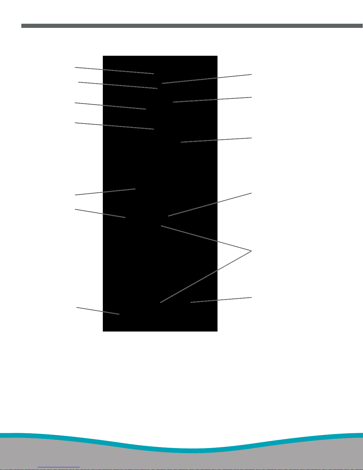
1. Sample Line Inlet
2. Main Power Indicator
3. Display Screen
4. Alarm Speaker (under front label)
5. Integrated Pneumatic Backup Switch
6. Control Wheel
7. Injector Module Tubing Outlet
8. Injector Module Cable Inlet
5
9. Water Trap Bottle
10. Purge Port
11. INOMAX Gas Inlets
12. Blender Gas Outlet
13. Ethernet Port
14. Infrared Connector
15. USB Port
16. Water Separator Cartridge
23
22
21
20
19
17. Water Trap Bottle
18. Sample Gas Outlet Port
19. Clamp Assembly
20. Electrical Cord Inlet
21. Equipotential T erminal
22. ON/Standby Switch
23. RS232 Port
Figure 1-1 INOmax DSIR Front View Figure 1-2 INOmax DSIR Rear View
18
17
Part No. 20717 Rev-01
2014-07
1-3
1
2
3
5
6
8
10
4
7
9
11
13
1. INOmax DS
IR
2. INOmax DSIR Mounting Post
3. Clamp Assembly
4. INOMAX Regulator (2)
5. INOblender
6. Small Part Bin
7. INOmeter
8. INOMAX Cylinder
9. Cylinder Holding Bracket
10. Cylinder Mounting Strap
11. Oxygen Cylinder Bracket
12. Caster Lock Lever
13. Caster (4)
Figure 1-3 INOmax DSIR and Cart
1-4
12
Part No. 20717 Rev-01
2014-07

(Intentionally left blank)
Part No. 20717 Rev-01
2014-07
1-5
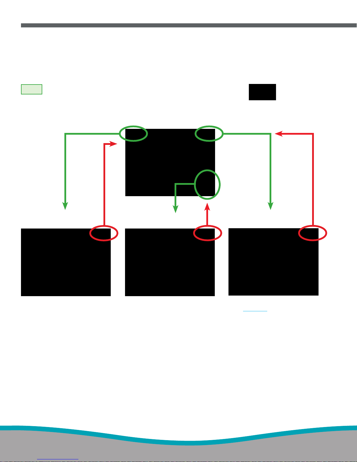
Navigating the Display Screens
Note:
The specic level is identied by the highlighted card on the Menu Button.
The red arrows indicate going back to a previous screen.
Recent Alarms Screen
(second level)
Main Screen (rst level)
Patient Information Screen
(second level)
Menu Screen
(second level)
1-6
Navigating the Menu Screen
(see page 1-8)
Part No. 20717 Rev-01
2014-07
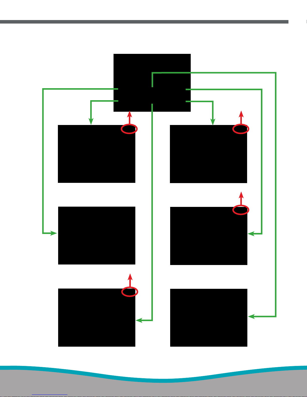
Menu Screen
(second level)
Low Calibration Screen Settings Screen
Pre-Use Wizard Alarm History Screen
High Calibration Screen Automated Purge Screen
Part No. 20717 Rev-01
2014-07
1-7
19
1
3
2
4
5
6
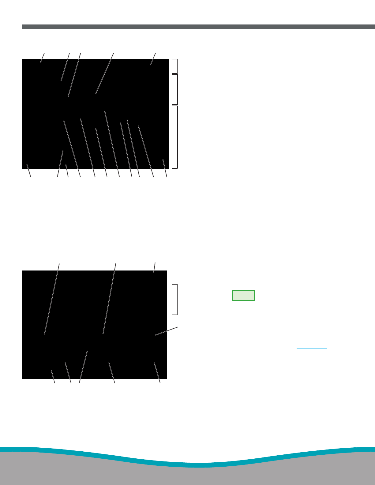
Main Display Screen
• On the main screen the user can
7
view alarm messages, monitored
values and graphical information.
• By pressing the “Menu Button” on
the touch screen (top right hand
corner), the user can access the
menu screen (see Figure 1-5 ).
8
10
1718
16
15
14
13
12
11
9
1. Alarm Silence Button
2. Upper Alarm Limit Button
3. Lower Alarm Limit Button
4. Monitored Value
5. Menu Button
6. Text Message Area
7. Monitor Area
8. Graphical Area
9. Patient Information Button
10. Sample Line Icon
11. Water Trap Bottle Icon
12. Inspiratory Limb Icon
Figure 1-4 Main Display Screen
1
8
910
1. Pre-Use Checkout Button
2. Auto Purge Button
3. Return to Previous Level Button
4. Monitor Area
5. Alarm History Button
2
7
6. Settings Button
7. High Calibration Button
8. High Calibration Due Date
9. Low Calibration Button
10. Last Low Calibration Date
Figure 1-5 Menu Screen (second level)
13. Injector Module Icon
14. Delivery Line Icon
15. Integrated Pneumatic Backup Line Icon
16. Integrated Pneumatic Backup Switch Icon
17. Delivery Setpoint Display
18. NO Delivery Setpoint Button
19. Cylinder Icon
Menu Screen (second level)
3
• On the menu screen the user can
access the Pre-Use Checkout
(#1) and the Auto Purge (#2)
wizards.
4
Note:
The Pre-Use Checkout
and Auto Purge buttons
are inactive (greyed out) if
a dose is set.
5
• To review the complete alarm
history, press the Alarm History
button (#5), (refer to Section 5/
Alarms).
• To initiate a low (room air) or high
calibration, press either the Low
Cal (#9) or High Cal (#7) buttons.
6
(refer to Section 6/ Calibration).
• Press the Settings button (#6) to
view circuit ow and calculated
delivery graphs, change display
brightness, change alarm volume,
change time zone and view
software
revision (see
F
igure 1-
6).
1-8
Part No. 20717 Rev-01
2014-07

8
1. Return to Previous Level Button
2. Monitor Area
3. Display Brightness Button
4. Time Adjust Button
7
Figure 1-6 Settings Screen
1
2
3
4
6
5. Software Revision
6. Alarm Volume Button
7. Calculated Delivery Graph
8. Circuit Flow Rate Graph
5
Settings Screen (third level)
• The circuit ow graph, combined with
calculated delivery graph, is a user level tool to
ascertain NO delivery system limitations in the
context of mechanical ventilation.
• The circuit ow rate graph displays the
real time peak and average ow rate in the
breathing circuit over a 10 second time period,
as measured by the injector module. The
area in green represents the circuit ow range
where the INOmax DS
system is rated to
IR
deliver NO from 1-80 ppm. (see maximum NO
delivery graph page 1-25). Display graphic
areas in yellow represents where some
inaccuracy of NO delivery is to be expected.
• The calculated delivery graph displays the
delivery subsystem calculated % error in NO
delivery compared to the desired set dose
over a 10 second time period. The green
to yellow transition points are dened to be
NO delivery error of +20% (over-delivery)
to -20% (under-delivery) compared to the
desired NO set dose. High set dose levels,
high peak inspiratory ows and proportional
NO ow control inaccuracies can contribute
to the indicating arrow varying from the ideal
midpoint.
Note:
• If the NO dose is not set, both graphs
will remain inactive.
• See page 1-25 for further explanation
of maximum deliverable NO
concentration.
Part No. 20717 Rev-01
2014-07
1-9

Display and user controls
The INOmax DSIR has a color touch screen display and a control wheel for adjusting and entering user
settings. The buttons on the touch screen and the control wheel perform a variety of functions using a threestep procedure (see “Setting and making changes on the INOmax
The touch screen buttons and control wheel are used to:
• Set the concentration of delivered NO
• Adjust alarm limits
• Silence alarms
• Calibrate the sensors
• Review alarm history
• Dene setup options
• Enter patient information
DSIR” see page 1-12).
Note:
• If a button has been selected and no activity has been sensed within 20 seconds, the display will
return to its previous condition. If a button is greyed out, it is not active.
• Position delivery system so user screen is unobstructed and the speaker is not covered.
When a value is being changed, pressing the
"Cancel Active Status" button during editing will
stop the change and return the parameter to its
original value (similar to the escape key on a
computer).
1-10
Part No. 20717 Rev-01
2014-07

Main Screen
Cylinder icons are not visible and the NO delivery
setpoint button will remain inactive until the
INOmax DS
recognizes an INOMAX cylinder.
IR
Caution:
High frequency and/or high intensity light
emission, in the area of the INOmeter, may
interfere with communication between the
INOmax DS
and the INOmeter on the
IR
INOMAX cylinder (see page 1-15).
The cylinder icons will appear on the main screen in
relation to their position on the cart when the user is
facing the INOmax DS
Note:
When using the transport regulator/cap
.
IR
assembly (PN 10022) only one cylinder
will be displayed.
Part No. 20717 Rev-01
2014-07
When an INOMAX cylinder valve is opened, the
cylinder handle graphic will turn green representing
an open INOMAX cylinder valve.
1-11

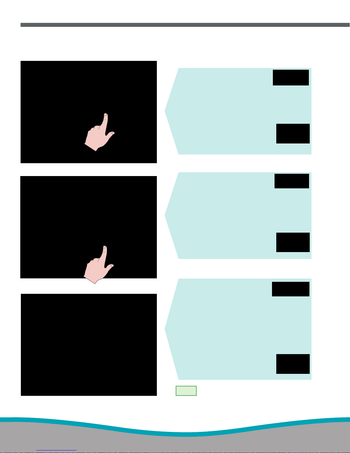
Setting and making changes on the INOmax DS
IR
Dose settings
Displayed dose settings are 1, 5, 10, 20, 40, 60 and
80 ppm. Each click on the control knob corresponds
to a known change in dose. The incremental dose
per click corresponds to a value dependent upon
the dose range in which the change is made, as
illustrated in the table at right.
Dose Settings Adjustments
Dose Setting Range Dose Change Per Click
< 1 ppm 0.1 ppm
1 to 40 ppm 1 ppm
40 to 80 ppm 2 ppm
1. SELECT
(press) a button on the touch
screen associated with the
desired function. (An audible
beep will sound when a button
is selected, and the button will
be displayed in inverse video.)
1-12
2. ROTATE
the control wheel clockwise or
counterclockwise to adjust the
value.
Part No. 20717 Rev-01
2014-07

3. CONFIRM
the selection by pressing the
control wheel or the button
associated with the desired
function again.
Note:
• After conrming a desired
dose, the NO alarm
setting (high and low) will
automatically be set for the
rst setting only.
• Any other changes will
require the high and
low alarm settings to be
adjusted.
• Also a two minute lockout
period will prevent the
low NO monitoring alarm
from occurring while the
measured values stabilize.
The Monitor Alarm Delay
Active indicator is not active
following a dose change
from zero.
Part No. 20717 Rev-01
2014-07
1-13
Settings Screen Adjustments
Access the settings screen (third menu level).
Display Brightness setting
1. Push the display brightness
button on the touch screen.
2. Turn the control wheel to indicate the display
brightness level desired. Choices range from
one (darkest) to 10 (brightest).
3. Push the control wheel to conrm the
selection.
4. When nished with the
menu screen, push the return
to previous level button on the
touch screen.
Alarm Volume setting
1. Push the alarm volume
button on the touch screen.
2. Turn the control wheel to
indicate the volume level desired. Choices
range from one (softest) to ve (loudest).
3. Push the control wheel to conrm the
selection.
4. When nished with the
menu screen push the return
to previous level button on the
touch screen.
1-14
Time Adjust setting
1. If the "Time" button is pressed
the Time Adjust screen will
appear.
2. Press the Hour or Minute button on the
touch screen.
3. Turn the control wheel to adjust the
displayed hour or minute.
4. Push the control wheel to conrm the
selection.
5. When nished with the menu
screen push the return to
previous level button on the
touch screen.
Note:
Changing the displayed time does not
impact the time written to the INOmeter
since the time written to the INOmeter is
the GMT time, not the displayed time.
Part No. 20717 Rev-01
2014-07

Infrared Communication between the INOMAX Cylinders and
the INOmax DS
IR
WARNING:
Loss of communication between the INOmax DSIR and the INOmeter for more
than one hour will result in interruption of INOMAX delivery.
The INOmax DSIR has an interface using infrared (IR) technology which allows the INOmax DSIR to
communicate with the INOmeter
INOMAX cylinder for the correct expiration date and cylinder concentration. The INOmax DS
(which is mounted to each INOMAX cylinder). The INOmax DSIR checks the
also transmits
IR
a conrmed patient identier to the INOmeter on any open INOMAX cylinder.
The INOmax DS
cart (PN 10018) has a cover (see Figure 1-7, ) with an infrared transceiver mounted
IR
1
directly above each INOMAX cylinder. When INOMAX cylinders are loaded, communication will take
place between the INOmax DS
INOmax DS
is complete. A cylinder icon will be displayed on the main screen when an INOMAX cylinder is
IR
recognized by the INOmax DS
and the INOmeter (see Figure 1-7, ) after the boot up phase of the
IR
IR
(see “Loading INOMAX Cylinders onto the INOmax DS
Caution:
Nothing should be placed between the INOmeter and the cart to which it is attached.
Cart”, page 1-17).
IR
2
IR Communication Interference
The INOmax DSIR transceiver is located under the cart cover and should be protected from outside IR
sources. The INOmax DS
The INOmax DS
transceiver transmits via a 30 degree transmission cone projecting towards the oor (see
IR
dotted lines in Figure 1-7). The specications of the IR beam call for it to have a range of 20 cm (7.9 in). Based
on these specications it sould not affect other devices in the vicinity of the INOmax DS
cart was designed to protect the INOmeter from external light/IR energy sources.
IR
.
IR
The INOmeter uses a lower energy source which results in a lower IR beam range than the INOmax DS
The INOmeter does not transmit IR signals unless it is mounted on the INOmax DS
Caution:
A strong magnetic eld could affect the ability of the INOmeter to detect if the cylinder valve is
opened or closed. This may affect the ability of the INOmax DS
or closed) of the cylinder valve.
If there is interference with the INOmax DS
will not be displayed and a “Cylinder Not Detected” alarm will activate if there is a set INOMAX dose.
If IR communication interference occurs, we recommend taking the following actions:
• Move the external IR source
• Move the INOmax DS
cart to reduce the external IR source in the area of the INOmeter
IR
• Shield the INOmeter from the suspect IR source
If the actions listed above do not remedy this issue, the transport regulator/cap assembly (PN 10022) may
be utilized.
Part No. 20717 Rev-01
2014-07
cart.
IR
to detect the position (open
IR
/INOmeter communication, the cylinder icon on the user screen
IR
cart.
IR
1-15

External Light Interference
Caution:
High frequency and/or high intensity light emission, in the area of the INOmeter, may interfere
with communication between the INOmax DS
and the INOmeter on the INOMAX cylinder.
IR
If there is interference with the INOmax DSIR/INOmeter communication, the cylinder icon on the user screen
will not be displayed and a “Cylinder Not Detected” alarm will activate if there is a set INOMAX dose.
Test results have demonstrated susceptibility to unintended infrared energy from articial light sources. Most
notably, various compact uorescent lighting xtures that focus or reect light, increasing the light intensity in
the vicinity of the INOmax DS
cart, could affect INOmeter communications.
IR
If external light interference occurs, we recommend taking the following actions:
• Move the interfering light source
• Move the INOmax DS
cart to reduce the high intensity light in the area of the INOmeter
IR
• Shield the INOmeter from the suspect light source
If the actions listed above do not remedy this issue, the transport regulator/cap assembly may be utilized.
Figure 1-7
1-16
1
2
Part No. 20717 Rev-01
2014-07

Loading INOMAX Cylinders Onto the INOmax DSIR Cart
Note:
2
Check the INOMAX gas cylinders for the correct product identity labels, cylinder concentration
and expiration date.
4
Loading the rst
INOMAX cylinder
on the cart will
result in a cylinder
icon displayed on
the screen .
1
2
1
3
Loading a second
INOMAX cylinder onto
the cart will result
in a second cylinder
icon displayed on the
screen .
3
4
Part No. 20717 Rev-01
2014-07
1-17
INOmeter Operation
•
Removal of the INOmeter from the cylinder must be performed by authorized personnel. Do not
dispose of the INOmeter.
•
INOmeter battery replacement is only to be performed by authorized personnel.
•
The INOmeter replaces the standard rubberized cylinder valve handle on the INOMAX cylinders and
is used to open and close the cylinder valve. The INOmeter is a time-metric device which records the
amount of time the INOMAX cylinder valve is opened.
•
The INOmeter is designed for use with INOMAX cylinders and with the INOvent, INOmax DS and
INOmax DS
•
When used with INOmax DS
INOmax DS
and the expiration date to the INOmax DS
communicated from the INOmax DS
delivery systems.
IR
, two-way infrared (IR) communication occurs between the
IR
and the INOmeter. The INOmeter communicates the INOMAX cylinder concentration
IR
. Patient ID (when conrmed) and dose information are
IR
to the INOmeter.
IR
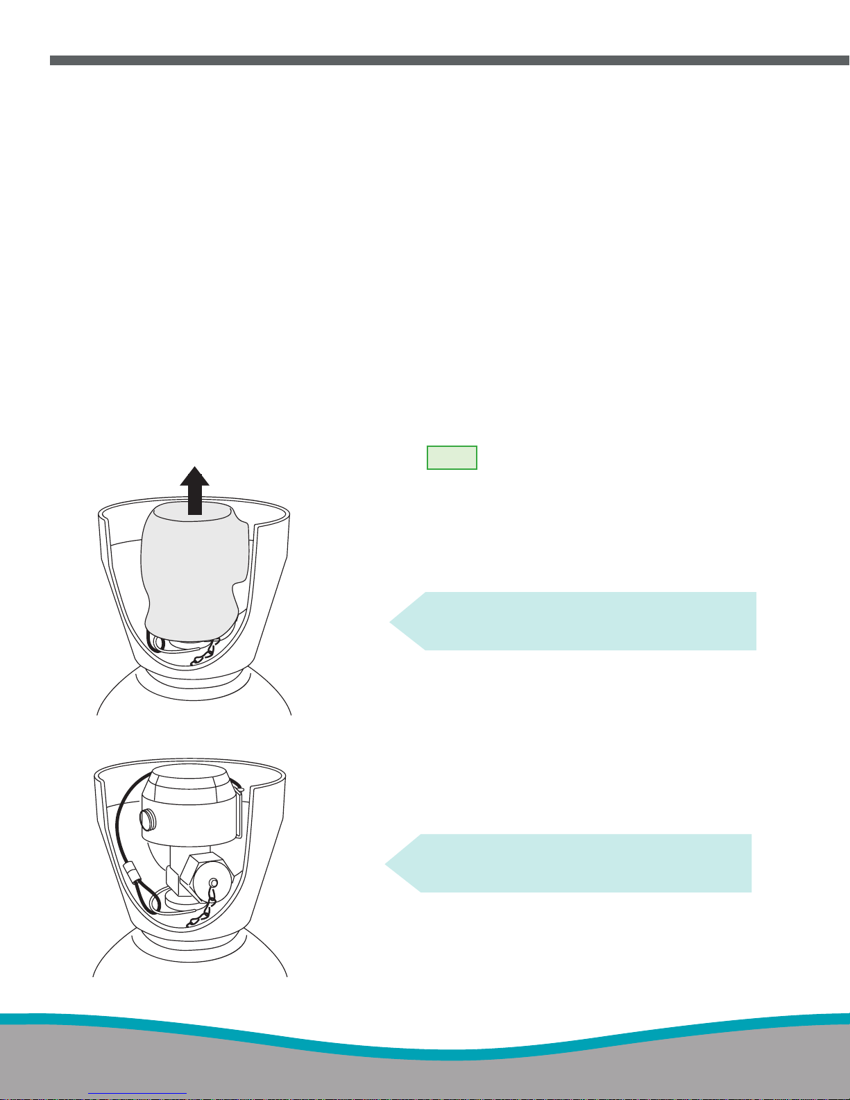
Figure 1-8
Note:
• Cylinders are shipped with the
INOmeter covered in a tamper-proof
seal.
• A valve lock is secured to the cylinder
by a lanyard.
• The lock must be removed to open
the cylinder valve for use.
1. Remove and properly dispose of tamper-proof
seal or covering (see Figure 1-8).
2. The lock is secured to the cylinder by a
lanyard (see Figure 1-9).
Figure 1-9
1-18
Part No. 20717 Rev-01
2014-07
 Loading...