

MALLINCKRODT CT 9000 ADV User manual

デー
区
JALLINCKRODT
00
Digital
ADV
Injection
System
INSTALLATION
SERVICE
MANUAL
800961-C
CT
9000°
ADV
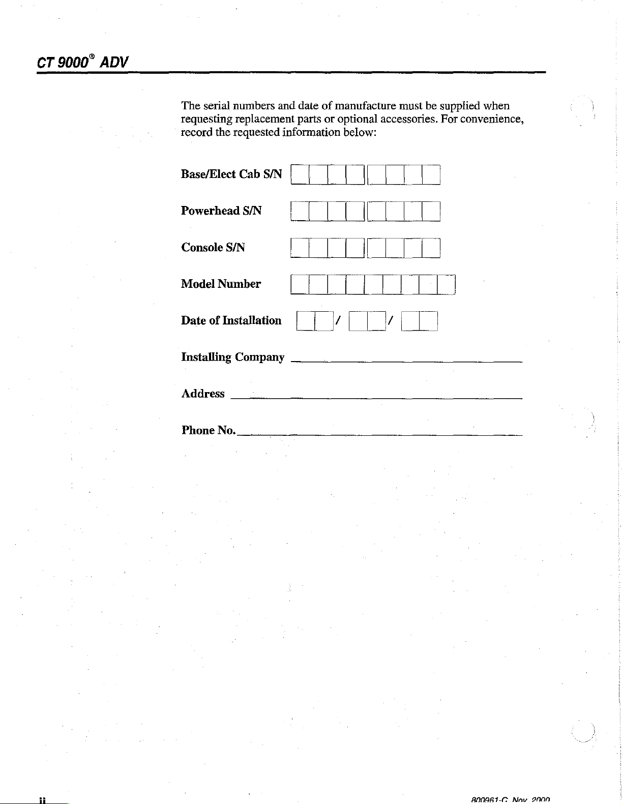
The
serial
numbers
requesting
record
Base/Elect
Powerhead
Console
Model
Date
replacement
the
requested
Cab
S/N
S/N
Number
of
Installation | / |
and
date
parts
information
S/N
|
of
manufacture
or
optional
below:
|
must
accessories.
[
be
supplied
For
|
|
when
convenience,
|
Installing
Address
Phone
No.
Company
HH
i
B00961-(0
Nov
2000

FOREWORD
Congratulations
ADV
Digital
to
provide a quality
world.
Injection
on
your
product
purchase
System.
to
of
the
The
CT
support
区
JALLINCKRODT
Liebel-Flarsheim
9000™
better
ADV
health
represents
care
CT
9000™
our
throughout
effort
the
MEANINGS
小
OF
SYMBOLS
Regardless
will
deny
misuse
of
operating
carefully
CT
9000™
Please
Caution
DANGER!—Hazards
death.
WARNING!—Hazards
CAUTION!—Hazards
damage.
of
its
owner
or
abuse
or
read
ADV.
regard
symbol.
how
occurs
servicing
this
any
well a piece
the
expected
unintentionally,
the
equipment
manual
Retain
message
and
this
which
which
which
the
manual
that
could
could
could
of
equipment
safe,
efficient,
Operator's
for
follows a Danger,
result
result
result
is
simply
is
unknown.
Manual
future
in
severe
in
personal
in
equipment
designed
and
because
reference.
misuse
quality
the
We
urge
before
Warning,
personal
injury.
or
or
service.
proper
property
method
you
to
servicing
or
injury
abuse
Often,
the
or
800961-C
A
©
È
I
Nov.
2000
WARNING!—Electrical
Non-
Anesthetic
Remote
Printer
Primary
Secondary
handswitch
console
proof
console
hazards
which
could
result
in
personal
injury.

CT
9000°
ADV
Powerhead
Toggle
Push-push
Viewing
Injecting
Enabled
Scan
Time
On/Off
Angle
(Ready)
delay
switch
On/Off
Adjustment
IB
200m!
Partial
9
ho
Protocol
c
AN
o-
Cn
ビエ
in
Date
Syringe
Patient
Protocol
Auto-Fill
Auto-Volume
Start/Stop
volume/size
volume
volume
Key
Key
Key
800961-C
Nov.
2000
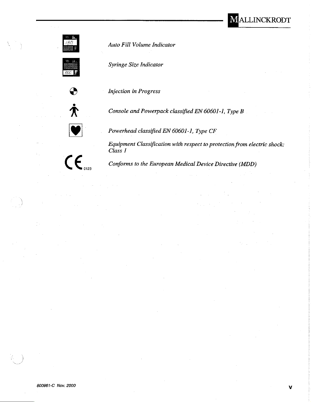
Auto
Fill
Volume
Indicator
区
JALLINCKRODT
Syringe
Injection
Console
Size
in
and
Powerhead
Equipment
Class
1
Conforms
Indicator
Progress
Powerpack
classified
EN
Classification
to
the
European
classified
60601-1,
with
Medical
EN
Type
respect
Device
60601-1,
CF
to
protection
Directive
Type
from
B
electric
(MDD)
shock:
800961-C
Nov.
2000

CT
9000°
ADV
SYSTEM
OVERVIEW
Figure
SERVICE
SPECIFICATIONS
DIMENSIONS
WEIGHT
POWER
VOLTAGE
ELECTRICAL
ENVIRONMENTAL...
SINO
FILLRATR...............
SYRINGE
Table
(users
1-1.CT
TECHNICIAN
REQUIREMENTS
REQUIREMENTS
AAA
HEATER.................
9000
ADV
QUALIFICATON
느 니 이 니 나
....
LEAKAGE
cccccccssccesesssssasserscosscsasicncesesesssesereccessaanassersecasseesessvessenseasesessseneenssseneases
나 나
eric
eee
eeeeerereeermeerasaraereresesamasereseeseaaaasenereseraerserserereseeasamaneimesasesessnen
Of
Digitallnjection
아 아 다 마 마 마 아 에 아 아 마 마 이 아 아 이 이 아 이 이 이 아 이 아 아
ooncocconcononorioncanonononnononacarorncnnnnrnaranenennonononrn
eee
Contents
nens
System
iii
rien
reni
saeaneamaamesssararensanemeneser
ce
eee
EEN
carie
eee
아 아
아 아 이 이 이 이 비 아
recarsi
eivezio
nn
rcenennenene
---
ennen
1-1
ernnnen
1-1
1-2
아 아 아 에 아 아 에 애
nie
zine
ien
ene
ro
ara
no
sersem
sanesarseresenenserere
иититтишиниинениния
이아
zize
iene
1-2
nenonranonos
1-2
..
1-3
13
FLOW
PRESSURE
INECTDELAY......................
SCAN
STORED
RATE
LIMIT
DELAY
PROTOCOLS
PARAMETERS
niro
eee
eee
eee
eci
ooo
eee
eine
eee
onen
ee
nie
ri
ven
einen
ena
oa
ieri
semer
eni
e n
Pe
eee
ie
eie
ieri
KPA
den K RAP e A0
einer
ener
PPR P Koa e een
eine
neenzeine
ené
1-4
1-4
1-4
14
1-4
vi
800961-C
Nov.
2000
区
|ALLINCKRODT
INSTALLATION
UNPACKING
INSTALLATION
ELECTRONICS
Remote
Printer
Primary
Secondary
Powerhead
Power
POWERHEAD
Heater
ELECTRONICS
CONSOLE
Electronics
ooonnococonconnonconannnconannonancscano
AND
ASSEMBLY
PROCEDUBES
oro
rene
ra
nnnnnnao
PROCEDURE
CABINET
Handswitch
COMMOCtiON
ccccscssscsscnessesssersssonssessessossessseessssssssssssessscensosesseasseansessersessasenees
Connection
.........ccscccccsssrcecscsneeensseeeessennaeesenaaeeetseseeaaaeesepsesensaenessesenseadeeteeneas
Console
Console
Connection
Cord
Connection
....................
sise
ii
Blanket
Connection
CABINET
iii
Сапе!
.es
CONNECTİON...
aeree
СоппесйОп
iie
nei
ree
eee
..........
sise
nie
iene
eee
ieri
nor r rea
eee
eee
iene
cere
nenes
rana
ss
s
rr
nenes
een
onen
2-1
ea
2-1
2-3
2-3
2-3
2-3
.2-3
2-3
noo
naconnnorconcornnonronencarncno
iene
iene
nen
eee
ros
2-3
2-4
2-4
TURN
ON
THE
Figure
CT
2-1.
9000
ADV
Start-up
линии
Menu
RECORDTHEVERSİONLEVEL.........................
ENTER
LANGUAGE
THE
PRESSURE
AND
REGISTRATION
LIMIT,
TIME,
NAME
DATE,
.............
ини
ee
ии
ининин
ereta
ее
линении
KE
2-4
2-5
2-5
2-5
800961-C
Nov.
2000
vii
CT
9000°
ADV
THEORY
PRESSURE
POWER
МАМ
VOLTAGE
MOTHERBOARD
OF
OPERATON
CONTROL
PACK
Figure
РОУ"ЕВ
Figure
Power
Powerhead
Tabie
OVERVMEW...............
3-2.
3-3.
SELECT
SupplieS
3-1.
rrssenennrennereennennneenenrsenenenenneenennenereneeneee
Power
ПМРОТ...........
Main
Interface
Powerhead
Pack
Power
BOARD
иене
in
eee
OvervieW
INput
DB-25
nn
ee
,pe
линии
........
ii
Pin
Designations...
3-1
昌和
cenner
ara
rincororas
eeeie
sieve
rie
reni
reni
rione
rene
ere
nce
cenere
ie
тии
eee
ee
RSA eno
PRK
KPK R AAR A KA
eee
R
OP
Renee
KRKA
PRA e o
cenere
PPR
een R Pen
PRAP n neo
een
eee
Panev
Knee
rene
né
Figure
Table
Auxiliary
Handswitchinterface.....................................
Table
Status
Table
Mother
Table
Console
Table
3-4,
Typical
3-2.
Motor
I/O
3-4.
Handswitch
LED'S
3-5.
Motherboard
Board
3-6.
Mother
ConnectorS
3-7.
LCD
Flyback
SignalS… せ ae
Interface
oo...
BUS
Module
..
Connector
Connectors
Board
Ведщаюг
Status
Slot
Interface
LED's
ire
Configuration
Connector
СИСИй
Pinout
...........
sise
sisi
LE
SEE
EAR
....
RE
KLEE
иене
PEER
LER
ELDELE
нинниининиия
00
ss
RENEE
ERE
EELES
A
viii
800961-C
Nov.
2000

区
|ALLINCKRODT
EEPROM
RAM
EPROM
Digital
Analog
JumpersandLED's...................01eeeeree
Table
Input/Output
Table
Table
Table
Table
Table
CONSOLE
Figure
Operation...
Operation
Operaton
to
Analog
to
.............
Converter
Digital
Converter
ri
Operation
Operation
..
ss
ss
erer
3-8.
CT
9000
ADV
CPU
BoardHardwareSummaly...................................
Definition
3-9.
CPU
Board
3-9.
CPU
Board
3-9.
CPU
Boardto
3-9.
CPU
Board
3-9.
CPU
Board
OVERVIEWW
3-7.ConsoleOvetview.........................................
.........................
to
Motherboard,
to
Motherboard,
Motherboard,
to
Motherboard,
to
Motherboard,
.ee
eee
Pins
PinsJ6AthruJ20C................................
PinsJ21Athruk2C................................
Pins
Pins
J1A
K3A
K18A
thru
thru
thru
een
J5C
K17C
K32C
enem
....
ーーー…ー…ー
0
sameener
..
ne
emare
aeeeeemerenene
000
rn
cnnenan
ras
...
아
...
...
800961-C
MAIN
VIEWING
CONSOLE
Power
Keyboard
Speaker
ConsoleCPU...............................
Table
Display
2000
Nov.
SupplieS
3-10.
Controller...
ANGLE
BOARD
rien
Interface
Contraj
.es
Hardware
BOARD
10
Summaly.................................
siennes
.0..
eee
reeeeeeeemeeereerereeaneeemeeeereeszeren
eee
ERE
REELLE
eee
irene
sera
rameesasenerane
EDER
eeerieneese
rn
ones
sener
3-32
3-33
3-34
ix
CT
9000°
ADV
POWERHEAD
Figure
MAIN
POWERHEAD
Table
MICROCONTROLLER
HEATER
RS-422
KEYBOARD
Table
NOIA
POWER
LAMP
‘MOTOR
STATUS
INTERFACE
Table
OVERVIEW
3-9.
Powerhead
3-11.
BLANKET
TNTEREACE
3-12.
SUPPLIES
INTERFACE
LEDS
3-13.
Powerhead
AND
Syringe
Status
Li...
eracerrarenererearacerenenanaceraasnarenases
Functional
BOARD
DB-25
sessssseesescsessececnensescesensoesserenesenssoseusseessasseacescesasivasccegenssteersesessnenees®
CONTROL
SENSOR
..............
oc.
INTERFACE
Size
Sensind
eeccsescsssccseesessscessesesaescncesaecscensocesceesescnsenesaenevaseesaseesoeeaesaeaseaseseaneassaeee
LED'S
.ee
Diagram
Pin
DesignationS
..
000
emer
ss...
eee
sd
grensen
saneret
sner
esserne
ss...
aremenseereesesseesereraeeramasermesesansasasesa
semra
sangere
nenene
een
nenene
rnemeseeaeesereranseramasesserarnez
str
serene
renee
skere
ss
renser
ener
..
ene
ge
ser
;
3-36
3-37
3-39
UNIVERSAL
Figure
Figure
Figure
Figure
INTERFACE
3-11.
3-12.
3-13.
3-14.
Universal
Universal
Universal
Universal
interfaceConnections...........................
Interface
interlaceConnecilons..............................
Interface
SCHEMATICS
CPU
BOARD
MOTHER
CONSOLE
800888-A
800977-А
VOLTAGE
BOARD800908REVE...................
CT
9000
¡TINE
UNIVERSAL
BOARD
800902
BOARD
BOARD
FOR
LCD
FOREL
SELECT
POWERHEAD
INTERFACE
800941
REVF...................
REVG
900906
DISPLAY
DİSPLAY
AAA
лилиями
REV
..............
Connections
Connections
L
eee
eee
emer
eee
(Detail)
(Detail)
erer
..
........................................
eee
ressama
nee
отииетии
нов
отивиионшитетивиотетитнине
rmeesrrererernseseneresez
3-46
3-47
3-47
i
eeneneneeneesnennennneee
3-54
3-55
3-56
3-57
CT
9000
DISPLAY
SCHEMATIC
CT
9000
BOARD
x
800569
HALL
800573
EFFECT
REVA.............e
REV
A
eee
eee
erer
emer
reemsararasana
aearaseesmessesesermsereneseeasassassararasane
800961-C
Nov.
3-58
3-59
2000

区
JALLINCKRODT
TROUBLESHOOTING
ERROR
ЕВВОВ
AND
МЕЗЗАСЕ$
INJECTION
Insufficient
Press
Invalid
METIA
Lock
the
That
name
Heater
To
continue,
(See
also
Overheating
To
continue,
(See
also
ERROR
CODES
FAULT
MESSAGES
.............
WAS
Syringe
OVERRİDE
injection!
syringe
already
thermistor
press
Fault
Message 东 22)
error.
press
Fault
Message
μμ
еее
PRESSURE
ES
...............
reeaermrreensermasanmmrmesereneeneanaseserasezan
LIMITED
eee
ii
κκοσε
κενο
eee
οσο
κκ
κατα
σκκκνος
4-1
4-1
4-1
4-1
Volume!
toinjectavailablevolume...........................................
4-2
4-2
in
place...
exists!
tracking
override.
override.
μῥῥῥϱῥϱ
issues
sine
error.
See
See
ff
23)
μμ
manual
for
further
eee
manual
for
further
.ee
-ϱ-ϱ“Ο“υΙΟΙΙΙὗμΓ“-“-
instructions.
eee
000090
instructions.
LEEDS
4-2
4-2
4-2
4-3
4-3
FAULT
Figure
Figure
Fault # 001
Brake
Fault # 002
Brake
Fault
Reverse
Fault # 004
Reverse
Fault
Safe
Fault # 006
Safe
Fault
Safe
MESSAGES
4-1.
4-2.
didnottumof......................
didnottumon.......................0..
#
003
relay
relaywouldnottumon........................................
#
005
relay
would
relay
would
#
009
relay
turned
μμᾖ᾿Ώ᾿ϐϱ᾿ὃϱὃὂϱ᾿ϱυυὨὨ-----.
Fault
Fault
Message
Message
Appearing
Appearing
een
would
not
not
on
not
turn
turn
turn
with
off...
Off
eeeeeeeeeeemeneenn
On
pe
no
failsafe
at
PoWerup
Protocol
eee
.................
MemoryMenu..............................
ener
iii
ee
siena
eee
eek
eramansanaraneeanennenı
een
4-3
4-4
4-4
4-5
4-5
4-5
4-5
4-6
4-6
4-6
800961-C
Nov.
2000
xi

CT
9000“
Fault # 010
PWM
Fault # 011
PWM
Fault # 012
PWM
Fault
PWM
Fault # 014
PWM
Fault
PWM
Fault # 016
Position
Fauit # 017
Lost
ADV
#
#015
power
stop
turned
D/A
conflicts
D/A
conflicts
013
D/A
conflicts
stop
would
stop
would
is
not
off
with
with
with
not
not
calibrated
head
communications...
with
A/D
A/D
A/D
turn
tun
ii
no
failsafe
(5V)
(2.5Ν)
(OV)
Off...
siennes
On
eee
eee
rennes
00...
eee
sis
een
i
nn
4-6
4-7
4-7
4-7
4-7
4-8
4-8
4-8
Fault # 018
Lost
console
Раий # 019
Flow
rate
errOT
Fault # 020
Motor
Fault # 021
Syringe
Fault # 022
Heater
Fault # 023
moving
Size
thermistor
Overheating
Fault # 024
Power
head
Fault # 025
Power
head
Fault # 026
Ram
past
extend
communications
wrong
sensind
direction
@TTOT
tracking
error
erOT
communication
flow
rate
error...
iii
limit
error
siens
kernerne
,ee
nier
error
inserer
rennes
erne
ere.
ee
0000
onen e nen R P
Keane R RP e RaO R an
409 아 아
이 이 아 아아
4-8
4-9
4-9
4-9
4-9
4-9
4-10
4-10
4-10
xii
Fault # 027
Ram
past
retract
limit
error...
issues
ne
ee
800961-C
4-10
Nov.
2000

Fault # 028
Unknown
power
head
fault...
区
JALLINCKRODT
sers
4-10
Fault # 029
Pressure
is
not
calibrated un
4-11
Fault # 030
Illegal
state
transition
ii
4-11
Fault # 031
Bad
power
Fault
No
power
#
032
head
head
communications
detected
.ee
na
eee
ennn
4-11
4-11
Fault # 033
Bad
EEPROM
detected
on
CPU
Board
lisser.
4-12
Fault # 035
Software
error
.........
inn
4-12
Fault # 036
NI
A
eee
emrenin
4-12
Fault # 037
ROM
Fault # 038
No
encoder
Fault # 039
EC
Fault # 041
Overvolume
Fault # 042
Console
Fault # 043
Power
RE-ASSEMBY
Figure
Figure
test
falled
iii
counts
RA
error
key
closedonpowerup.....................0
head
key
closedonpowerup..........................
OF
THE
4-3.
Critical
4-4. Critical
detected
detected
POWERHEAD
Dimension
Dimension
sise
een
of
End
of
Powerhead
Bracket
Assembly
200
1.0
ASSEMDIY
eee
..........
4-12
4-12
4-13
LE
ELLE
er
4-13
enenrneenenne
ener
4-13
4-13
4-14
iene
4-14
800961-C
Nov.
2000
xiii
CT
9000°
ADV
CALIBRATION
TOOLS
PLACING
FACTORY
POSITION
REQUIRED
UNIT
CALIBRATION..............
CALIBRATION
PRESSURE
PRESSURE
WITH
125
PRESSURE
PRESSURE
PRESSURE
IN
CALIBRATION
CALIBRATION
ML
COMPENSATION
CALIBRATION
CALIBRATION
CALIBRATION
ο
ο
oonmoncennnnornnonoonoonnncncoronncnnnoncnennnnerenen
CALIBRATION
eee
FOR
MAINTENANCE
GUALIFICATIONS..................
MAINTENANCE
LEAKAGE
AND
ener
SCHEDULE
GROUND
CONTINUITY
ου
MODE
니
니 나 나 다 아 아 사 아 아 아 아 이 이 이 어 아 이
ALL
FOR
200
FOR
200
FOR
100
FOR
30-50
eee
siennes
SYRINGE
ML
SYRINGE
ML
PUSHROD
ML
PUSHROD
ML
HAND-HELD
CHECKS
FACE
USE
SYRINGE
SYRINGE
iii
nera
rones
μμ
enormes
5-1
5-1
5-1
Re
Hee
te
ete
ten
5-2
이 이
00449
PLATES..................-...
이 아 아 의 5-4
rn
5-6
nn 아 5-6
SYRİNGE
amenna
..............................
.....................................
eee.
een
sanem
5-11
5-12
5-13
Figure
EXTERIOR
POWER-UP
POWERHEAD/PRESSURE
KEYBOARD
ELECTRONICS
FLOW
PRESSURE
CLEANING
CUSTOMER
RATE
PRESSURE
CONTROL
POWER
6-1.
Leakage
OF
COMPONENTS
CHECK
CONSOLE
CABINET
CHECK
LIMIT
THE
PACK
INTERFACE
CHECK
UNIT
SLEEVE
CONSOLE
Test
Set-up
.ee
JACKET
ie
............
...
iii
(Unit
.....
is
plugged
serbere
in)
etern
ere
Er
A
KAVE
ERE
ee
POKR
R A
EEN
Re
EELnEEE
xiv
800961-C
Nov.
2000

区
JALLINCKRODT
1
SYSTEM
OVERVIEW
800961-C
Nov.
2000
Figure
1-1.
CT
The
CT
9000
trast
medium
diagnostic
injection
with
microprocessor
This
manual
9000
ADV
daily
maintenance
Manual.
9000
ADV
ADV
Injector
into a patient's
images
is
accomplished
provides
Injectors.
obtained
of
Digital
control
service
For
the
Injection
is
designed
vascular
with
computed
with a motor-driven
of
the
flow
and
calibration
further
unit,
information
refer
to
System
to
inject a radiopaque
system
rate,
the
which
tomography
syringe
volume,
procedures
about
CT
operating
9000
ADV
enhances
con-
(CT).
mechanism
and
Each
timing.
for
the
and
Operator's
CT
1-1

CT
9000 ® ADV
SERVICE
TECHNICIAN
SPECIFICATIONS
QUALIFICATION
The
CT
9000
ADV
calibrated
*
+
*
Failure
service
DIMENSIONS
Conirol
Powerhead
Power
(i.e.,
ONLY
are
completely
have
read
Manual
are
properly
to
follow
technician.
Console
Pack
Electronics
Digital
by
qualified
familiar
and
understood
trained
these
Cabinet)
Injection
personnel
with
this
in
servicing
guidelines
could
System
who:
the
unit
manual
equipment
result
12 W x
(80 W x
3.5 W x
(9 W x
12 W x
(80.5 W x
8.4 D x
21 D x
16
41 D x
14 D x
should
and
the
of
in
serious
4.2 H inches
10.4 H cm)
Dx 6 H
16 H cm)
6.5 H inches
35.5 D x
be
serviced
Operator's
this
type.
injury
inches
16.5 H cm)
and
to
the
WEIGHT
Standard
Control
Powerhead
Power
POWER
Pack
REOUIREMENTS
Standby
Standard
VOLTAGE
Unit
automatically
240VAC.
ELECTRICAL
System,
complete
Console
REOUIREMENTS
adapts
LEAKAGE
for
38
Ibs
7
lbs
18
Ibs
13
lbs
less
115
280
input
(17.2
(3.2
(8.1
(5.9
than 1 A
VAC, 3 A,
VAC,
kg)
kg)
kg)
kg)
1.5
voltages
50/60
À,
50/60
from
Hz
100
Hz
to
Chassis
less
than
300
microamps
800961-C
Nov.
2000

ENVIRONMENTAL
CAUTION!
The
console and
these
components
operator
operation
DANGER!
Possible
ics.
WARNING!
The
20
than
patient
SYRINGES
explosion
The
unit
powerhead
gauss
this
injury.
injury.
and
limit.
limit
electronics
can
If
fluid
contact
hazard
is
not
designed
may
only
Operating
may
cause
cause
is
spilled
your
if
be
the
the
cabinet
the
authorized
used
for
operated
unit
unit
are
unit
to
on
either
in
the
use
in
explosive
in
within
to
malfunction,
not
malfunction,
service
presence
an
magnetic
区
JALLINCKRODT
spill-proof.
resulting
component,
personnel.
of
flammable
environments.
area
that
is
fields
resulting
Fluid
spilled
remove
located
that
are
in
operator
in
in
patient
from
anesthet-
beyond
higher
or
the
or
Syringe
FILL
RATE
Full
to
[Forward]
Sizes
forward
maximum
keys.
'
SYRINGE
HEATER
98° + 6° F (37° + 3°
pre-heated
(42°
C).
or
reverse
within
or
[Reverse]
contrast.
200
ml
(front-load)
200
ml
(pushrod)
125
ml
(pre-filled)
100
ml
(pushrod)
50
ml
(hand-held)
30
ml
(hand-held)
time:
13-100
sec.
Accelerates
approximately 3 seconds
key
in
C)
nominal.
Overtemp
conjunction
Maintains
condition
with
the
will
from
after
pressing
one
of
the
temperature
occur
at
107.6°
zero
the
[Fast]
of
F
800961-C
Nov.
2000

CT
9000?
ADV
NOTE:
The
syringe
125
ml
(pre-fill)
The
syringe
FLOW
RATE
200
125
100
30-50
PRESSURE
Pressure
pounds
bar
heater
heater
PARAMETERS
ml
Syringes
ml
Syringe
ml
Syringe
ml
Syringe
LIMIT
Units
per
for
type
syringes
for
square
use
push
inch
with
with
with
and
(psi)
the
pressure
turn
type
0.1—9.9
0.1 一 9.9
0.1—9.9
0.1—7.0
Range
25,
50—300
(in
50
2,
3,
7,
200
ml
(front-load)
sleeves
faceplate
ml/s
ml/s
ml/s
ml/s
(150*)
psi
increments)
10*,
14,
is
is
17,
P/N
P/N
21
and
800114.
800146
NOTE:
kg/em?
(*)
Used
pushrod
INJECT
Inject
SCAN
DELAY
Scan
STORED
12
protocols
to
denote
syringe
DELAY
Delay
Delay
Parameters
Parameters
PROTOCOLS
can
pressure
be
stored
2, 4, 7,
values
0—255
0—99
and
11*,
pertaining
sec
sec
recalled.
14,
18,
only
to
21
the
200
ml
1-4
800961-C
Nov.
2000

区
JALLINCKRODT
2
UNPACKING
INSTALLATION
AND
PROCEDURE
INSTALLATION
ASSEMBLY
When
check
damaged
express
is
later
agent
Store
tion.
The
subject
When
fragile
cal
shocks.
PROCEDURES
receiving
the
equipment
or
missing,
agent
discovered
within
the
the
unpacking
electronic
notes
15
equipment
storage
equipment
the
CT
to
days
area
the
parts.
9000
for
signs
don't
accept
the
problem
be
damaged
after
receiving
in
the
shipping
should
to
temperature
CT
9000
Don't
ADV
of
be
ADV,
drop
Digital
damage.
the
shipment
on
the
receipt
or
missing,
the
items.
cartons
clean
and
extremes.
remember
it
or
subject
Injection
If
any
until
dry
system,
of
the
until
or
bill.
notify
ready
and
that
it
to
other
items
the
freight
If
equipment
the
shipping
for
installa-
should
it
contains
mechani-
first
are
or
not
Refer
@
(©.
to
the
Checklist
After
unpacking,
record
Checklist:
ロロ
Inspect
Check
Check
ロロ
ロロ
ロロ
each
Console
Power
Powerhead
Printer
Console
Powerhead
Power
Ordered
the
the
the
included
identify
component's
pack
(Electronics
and
its
to
Power
to.
Cord
Accessories
exterior
Console
Console
of
Cable
case
in
the
front
these
associated
Power
the
for
parts
Serial
Cabinet)
pack
cable
pack
Console:
connector
dents
of
this
of
the
Number
hardware
cable
for
cracks
or
other
manual.
system
in
the
Installation
(optional)
or
bent
external
and
pins.
damage.
800961-C
Nov.
2000
2-1

CT
9000?
ADV
©
Inspect
Check
Check
cracks
Inspect
Check
Check
connector
inspect
Power
to
Check
ing.
Inspect
scratches.
Mounting
depend
Installation
order
tion.
the
the
Power
the
connectors
or
protruding
the
exterior
the
cable
the
Heater
for
the
Console
Cord.
crimping.
the
Power
each
the
on
the
Instructions
to
mount
exterior
of
pack
pins.
of
for
nicks
connector
cracks
Check
or
cable,
each
Cord
Accessory
Powerhead,
type
of
the
components
the
Power
cabinet
located
the
bent
for
to
for
on
Powerhead:
or
impairment
and
the
pins.
the
Powerhead
cable
for
nicks
or
ensure
Power
accessories
that
accompanies
to
pack:
dents
the
or
rear
due
scratches.
of
the
to
Powerhead
cable and
nicks
or
impairment
impairment
there
pack
your
are
no
and
Console
ordered. Refer
the
accessories
desired
cabinet
for
crimping.
Cable
the
due
due
to
crimp-
dents
or
will
to
the
configura-
in
Power
system's
ered
connections
musi
may
cabling.
cause
be
off
before
Connecting
generation
are
as
connecting
follows:
cabies
of
false
or
disconnecting
after
the
error
messages.
Unit
the
is
pow-
System
onnnos m am.
nana

区
JALLINCKRODT
ip
ELECTRONICS
Remote
An
optional
Printer
An
optional
Primary
A
15-pin
from
Secondary
A
second
to
and
Powerhead
A
25-pin
from
Handswitch
8-pin
remote
Connection
8-pin
printer.
Console
the
from
the
circular
circular
D-shell
Console,
Console
15-pin
D-shell
powerhead.
CABINET
Connection
DIN
connection
handswitch.
mini-DIN
connection
D-shell
an
optional
Connection
connection
allows
connection
sends
connection
second
Console.
sends
allows
and
sends
and
for
interfacing
for
receives
and
receives
receives
with
an
interfacing
information
with
to
information
information
to
an
and
and
Power
The
power
or
cally
CAUTION!
Use
Connection.
equipment.
power
Cord
supplied
connection.
220
VAC
sense
only
the
cards.
Units
POWERHEAD
Heater
A
and
Blanket
4-pin
connection,
receives
ELECTRONICS
Connection
power
cord
The
(50/60
the
supplied
Use
Hz)
input
power
of
other
installed
Connection
located
information
CABINET
connects
unit
can
without
voltage
cord
power
outside
on
to
and
CONNECTION
to
the
accept
either
modification.
during
cords
to
connect
could
of
the
the
bottom
from
power-up
power
result
U.S.
the
Electronics
115
The
Cabinet
VAC
unit
will
sequences.
to
the
Power
in
damage
must
use
hospital
of
the
Powerhead,
Heater
Blanket.
at
(50/60
Hz)
automati-
Cord
to
the
approved
sends
the
800961-C
Nov.
2000
CT
9000 * ADV
A
25-pin
sends
net.
and
CONSOLE
connection,
receives
located
information
on
the
to
bottom
and
from
of
the
Powerhead,
the
Electronics
Cabi-
TURN
ON
THE
CT
Electronics
A
receives
©
9000
Turn
located
power
located
the
15-pin
connection,
information
install
installation.
the
Operator's
©
Perform
Chapter
then
ADV
the
unit
on
the
switch
on
the
console
Cabinet
the
Pressure
of
the
6.
If
proceed
on
by
rear
located
Power
will
glow
Connection
located
to
and
on
from
Plate
the
Pressure
Manual,
Preventive
all
requirements
to
the
next
first
toggling
of
the
cabinet
on
the
left-hand
pack
and
and
the
the
rear
the
Electronics
Assembly.
Plate
P/N
800731,
Maintenance
for
section.
the
Power
and
then
side
on
the
upper
Start-up
Menu
of
the
console,
Cabinet.
Instructions
Assembly
or
Checks
these
pack's
pushing
of
will
are
800959
tests are
Power
the
console.
right-hand
be
sends
covering
contained
international.
listed
the
displayed.
in
passed,
Switch
Console
The
comer
and
in
LED
of
ANNNL4
NON.
anna

区
ALLI
NCKRODT
RECORD
Press
THE
VERSION
to
set
İLE
CT
pressure
limit,
LEVEL
Press
version
the
Press
[Exit]
9000
time,
date,
to
display
Figure
the
[Safety]
level
key.
language
and
important
2-1.
of
each
registration
safety
Start-up
key,
name.
information.
then
component
>
[>
i
Menu
the
[Version]
in
Setup
Safety
key.
the
Installation
Record
Checklist.
the
firmware
Press
ENTER
LANGUAGE
THE
PRESSURE
AND
REGISTRATION
LIMIT,
Press
Date,
these
TIME,
the
[Setup]
Language
items
are
DATE,
NAME
key
and
and
Registration
contained
enter
in
the
the
required
Name.
Operator's
Instructions
Pressure
Manual,
Limit,
on
P/N
Time,
entering
800959.
800961-C
Nov.
2000
2-5

CT
9000 * ADV
This
page
is
intentionally
left
blank
800961-C
Nov.
2000

区
JALLINCKRODT
POWER
PACK
OVERVIEW
The
the
third
of
1 I 1 1 1 1 1 1 1 1 1 1 1 I 1 1 1 1 1 i '
ーーーー
ニ
[ーーーー
power
MAIN
is
these
POWER
INPUT
pack
POWER
the
CPU
sections.
MAIN
consists
INPUT, second
BOARD.
4 1 1 1 1 1 1 1 1 1 1 1 1 1 1 1 1 1 1
of
three
Figure
UIPOWIMITOEZ
major
is
the
3-2
below
CPU
BOARD
functional
MOTHERBOARD
shows a block
sections.
J
First
is
and
diagram
Figure
3-2.
Power
Pack
Overview
800961-C
Nov.
2000

CT
9000 * ADV
MAIN
3)
POWER
|
INPUT
The
line
voltage
inlet.
double
output
power
filtered
VOLTAGE
power
power
is
below.
As
shown
pole,
is
connected
inlet
line
transformer,
transformer’s
24VAC. A complete
enters
in
double
and
the
voltage
SELECT
the
Figure
throw
to a line
line
is
senses
3-3,
circuit
filter
input
board,
primary
description
|
VOLTAGE
|
Power
the
breaker.
filter.
are
connected
to
the
which
the
line
winding
SELECT
Pack
through
power
The
VOLTAGE
is
voltage
of
inlet
chassis
actually
so
that
this
BOARD
is
The
circuit
ground
to
the
SELECT
mounted
and
configures
the
boards
an
IEC
wired
breaker
frame.
secondary
operation
; !
|
,
Iie
| ,
1 1 ㅣ
|
i 1
SV
|
FILTER
-
|
| '
一
|
1 !
VE
|
1
|
VOLTAGE
SENSE
一
二
引
5
RELAY
CONTROL
L
320
to a 3
of
the
The
board.
on
the
the
output
is
|
|
if
12VAC
i
=
1
12VAC
т
|
!
power
amp,
The
main
main
given
4
|
3-4
Figure
3-3.
Main
Power
Input
800961-C
Nov.
2000

区
ALL
NCKRODT
VOLTAGE
SELECT
BOARD
As
mentioned
for
sensing
transformer's
transformer's
Resistor
tripping
The
provides
bridge
The
U1’s
function
below
voltage
When
RESET
R1,
the
bridge
base
rectifier
MC34064
RESET
is
U1's
divider.
the
output
energizes
220V.
relay
U1’s
voltage
primary
This
K1
from
operation.
must
will
above,
the
line
primary
center
and
the
voltage
winding.
tap
varistor
circuit.
rectifier—BR1,
drive
for
varies
with
under-voltage
pin
is
an
output,
resetting
trip
input
relay
trip
uP
point,
RESET
voltage
high.
K1.
K1
point
RESET’s
will
oscillating
Once
fall
be
re-configured
the
to
approximately
VOLTAGE
and
to
keep
MOV1
R2,
DZ1
transistor
the
input
SELECT
configuring
The
sensing
the
circuit's
prevent
and
Q2.
AC
sensor,
not
an
input;
systems.
goes
When
is
low,
above
which
4.6V,
going
re-configures
occur
or
at
approximately
“hunting,”
primary
is
configured
75V
to
115V.
board
the
main
circuit
input
transient
C2—powers
The
dc
voltage
voltage.
U1,
trips
at
the
chip’s
the
rectified
sets
U1
trips,
high
turns
the
transformer’s
resistor
before
R4
the
is
responsible
power
samples
at
115VAC.
voltages
the
from
4.6V.
the
from
circuit
the
Note
intended
line
voltage
up
R3
and
R4
setting
on
Q2,
the
which
primary
155V.
adds
for
To
hysteresis
220V,
the
prevent
transformer's
and
that
is
as
for
line
a
to
Relay
times
R7
limit
K1
cannot
occur
current
handle
around
through
the
the
switching
K1
large
to
10
transient
point.
ma.
Transistor
voltages
Q1
that
and
some-
resistor
800961-C
Nov.
2000
3-5

CT
9000 ® ADV
MOTHERBOARD
The
MOTHERBOARD
each
of
which
sections:
*
Power
*
Powerhead
*
Servo
e
Auxiliary
*
Handswitch
e
Status
e
Console
will
be
discussed
Supplies
Interface
I/O
Interface
Interface
LED's
Connectors
consists
of
the
in
greater
following
major
detail
components,
in
the
following
Power
The
Remote
Remote
The
One
other
and
U17.
both
are
function,
and
The
ply
state
is
VBAT
reset
is
on
tristate
Supplies
power
on/off,
On/Off
main
side
of
side
then
to
When
sides
off.
However,
so
+12V
Power
Control
relay.
internally
(U17
switch,
connected
the
solid
PSO
supply
section
+3.5V
power
of
of
transformer
the
24VAC
the
24VAC
the
diode
the
solid
the
bridge
the
+3.5V
supplies
Supply
Output
Prior
to
held
at a high
pin
1).
SW1,
to
VBAT
state
relay. A subsequent
to
shut
consists
supply,
goes
goes
bridge.
state relay
and,
U17
requires
supply
are
off.
Control
(/PSO,
supplies
directly
therefore,
Input
U17
of
four
+5V
supply
24VAC
to a diode
through a solid
The
solid
is
off,
power
is
used
to
(/PSI,
pin
16)
are
establishing a voltage
level
at
ail
times
When
or
/PSI
by
the
momentary
to
provide a high
off
the
solid
is
forced
state
relay.
major
and
to
state
state
relay
the
24VAC
the
+5V
to
operate
power
U17
pin
used
on
VCC
by
the
low
by
switch
level.
falling
edge
functional
+12V
supply.
the
motherboard.
bridge,
relay,
is
controlled
is
not
and
+12V
the
remote
U17
while
8)
and
Power
to
control
(U17
+3.5V
the
motherboard
BR1.
SSR1,
applied
the
tne
pin
supply
on a console,
This
high
level
on
/PSI
sections:
The
by
to
supplies
on/off
+5V
Sup-
solid
3),
PSI
on
PSO
turns
will
3-6
Relay
relay
helps
Opto-isolator
and
the
when a long
K3
is
turns
on.
to
eliminate
the
motherboard
LED
side
used
U18
of
console
to
This,
noise
is
U18
isolate
along
+5V
with a filter
related
used
to
switch,
to
prevent
cable
is
from
U17
problems.
interface
SW1.
it
/PS!
Capacitor
from
attached.
pin 3 until
formed
to
by
the
C8
inadvertently
the
L3
and
console
is
placed across
turning
800961-C
solid
state
C34,
switches
on
Nov.
2000

区
JALLINCKRODT
+3.5V
The
supply
Power
The
rectifying
former
as
Supply
+3.5V
is
off.
supply
Pack.
adjustable
(D3
secondary
follows:
Vout = 1.25V
This
+4V
is
dropped
connected
+5V
Supply
The
+5V
cuitry
DC
converter
At
intervals
to
VR2-4
current
load
and
to
supply
and
the
of
impressing a voltage
to
build
filter
is
used
to
It
also
powers
regulator
and
1/4
center
(1+
U17
pin
is
used
CPU
capable
VR3
of
BR1)
tap
R13/R14) = 1.25V(1 + 1500/680) = 4V
to
approximately
1.
to
power
board.
The
of
sourcing
approximately
up
in
the
inductor
capacitor
C4.
supply
the
is
power
LED
supplied
and
filtering
voltage.
the
+5V
regulator
up
10us
(100kHz)
across
while
to
U17
located
VR3's
3.5V
on
+14V
(C9)
output
by
the
unregulated
the
D13
MOTHERBOARD
is a step
to
5A
of
output
VR2
inductor
also
L2.
supplying
when
the
front
main
of
trans-
voltage
before
being
logic
down
current.
connects
This
causes
current
+5V
the
DC
by
is
set
cir-
DC
VR2-5
to
to
the
VR2
determines
10us
interval
VR2-4
lapses
to
inductor
across
flow
inductor
The
the
output
are
and
try
and
the
from
divider
supply
voltage
is
runs
Vout = 2.21V
R4
and
C5
stabilize
the
to
when
keep
to
the
disconnected,
the
polarity
maintain
now
inductor)
the
circuit
against
the
directed
by
inductor
out
is
until
of
energy.
of
R6
an
internal
calculated
(1 + R6/R5) = 2.21V(1 + 2870/2210) = 5.08V
make
up
the
feedback
loop.
disconnect
output
the
magnetic
of
the
voltage
current
(due
the
and
in
to
diode
the
switch
RS
voltage
as
follows:
frequency
VR2-5
voltage
at
field
across
the
inductor. This
the
change
D2,
to
the
turns
is
used
to
reference
compensation
and
+5V.
in
the
the
in
voltage
load.
on
again
set
the
VR2-4
When
during
VR2-5
inductor
inductor
current
polarity
The
current
or
until
output
of
2.21VDC.
network
the
and
col-
changes
in
the
will
the
voltage
The
used
to
of
800961-C
Nov.
2000
3-7

CT
9000 ® ADV
+12V
The
board
The
tion
voltage
Powerhead
The
powerhead
the
RS-422
(TXDB)
RS-422
cations
from
coder
Supply
+12V
+12V
of
Vout = 2.21V
supply
and
is
regulator
the
divider
for
the
used
Interface
powerhead
DB-25
powerhead
transmitter
from
the
receiver
(RXDB)
the
POWERHEAD
quadrature
+12V
DB-25
generate a motor
pin 6 indicates
that
the
motor
the
is
is
supplied
as
the
is
identical
circuit
supply
(1 + R3/R2) = 2.21V(1 + 9760/2210)
interface
connector
connector
U4
pin 9 translates
CPU
board
U13
pin
and
motor
pulses
direction
motor
to
the
MOTHERBOARD,
bulk
supply
to
the
which
board
are
is
sets
the
is
calculated
provides
for
11
translates
encoder
input
signal
the
and
the
is
given
transmission
quadrature
to
the
to
to
the
expelling. A low
for
the
POWERHEAD
+5V
regulator
output
as
follows:
interface
CPU
board.
in
Table
serial
the
RS-422
CPU
board.
J-K
flip
flop
CPU
on
voltage.
between
The
3-1.
communications
to
the
pulses
The motor
U14
board. A high
U14
filling.
the
CPU
board.
with
the
excep-
The
output
=
11.97V
the
pin
out
for
POWERHEAD.
serial
communi-
transmitted
en-
pin 3 and 4 to
on
U14
pin 6 indicates
The
serial
boards
pin
15.
used
to
communications
are
combined
The
resulting
monitor
powerhead
between
by
U6
signal
communications.
the
pin 6 and
is
output
POWERHEAD
converted
to
connector
to
RS-422
J13
and
and
CPU
by
may
U4
be
800961-C
Nov.
2000
 Loading...