

Mallinckrodt 700 Service Manual

anual Name:
l
art Rev Date: G-061875-00 Rev. A (11/99)
Ventilator System Service Manua
700 Series
....................
Part No. G-061875-00
Rev. A
November 1999
Ventilator Systems
Service Manual
Service Manual
675 McDonnell Blvd.
P.O. Box 5840
St. Louis, MO 63134

.............................................................................................
Copyright Information
Copyright 1999 Nellcor Puritan BennettÔ Inc. All rights reserved. The 740
Systems are manufactured in accordance with Nellcor Puritan Bennet t pro prietary info rmati on, covere d
by one or more of the following U.S. Patents and foreign equivalents: 5,524,615; 5,540,222; 5,596,984;
5,632,270; 5,664,560; and 5,673,689.
The information contained in this manual is the sole property of Nellcor Puritan Bennett Inc. and may
not be duplicated withou t permission. This manual may be revised or replaced by Nellcor Puritan
Bennett Inc. at any time and without notice. You should ensure that you have the most current
applicable version of this manu al; i f in doubt, contac t the Technical Publ ic ations Dep artment of Nell cor
Puritan Bennett Inc. at the location listed in the following section entitled “Comments.” While the
information set forth herein is believed to be accurate, it is not a substitute for the exercise of
professional judgment.
The ventilator should be operated and serviced only by trained professionals. Nellcor Puritan Bennett’s
sole responsibility with respect to the ventilator, and its use, is as stated in the limit ed warranty provided.
Nothing in this manual shall limit or restrict in any way Nellcor Puritan Bennett’s right to revise or
otherwise change or modify the equipment (including its software) described herein, without notice. In
the absence of an express, written agreement to the contrary, Nellcor Puritan Bennett Inc. has no
obligation to furnish any such revisions, changes, or modifications to the owner or user of the
equipment (including its software) descr ibed herein.
Trademarks
Nellcor Puritan Bennett , P TS 2000, Breathlab, 700 Se ries, 740, and 760 are registered
trademarks of Nellcor Puritan Bennett Inc.
Ô
and 760Ô Ventilator
Addresses
Manufactured by Corporate Headquarters European Office
Nellcor Puritan Bennett Ireland Mallinckrodt Inc. Mallinckrodt Europe BV
For Puritan-Bennett Corporation 675 McDonnell Boulevard Hambakenwetering I
A subsidiary of Mallinckrodt Inc. P.O. Box 5840 5231 DD’s-Hertogenbosch
2200 Faraday Avenue St. Louis, Missouri 63 134 USA The Netherlands
Carlsbad, CA 92008-7208 USA
Phone: 760.603.5300 Phone: 314.654.2000 Phone: +31.73.6485200
Fax: 760.603.5902 Fax: +31.73.6410915
ii
700 Series Ventilator System Service Manu al G-061875-00 Rev . A (11/99)
.........

..........................................................................................
.
Preface
This manual is intended to provide information needed to service the Nellcor
Puritan Bennett 700 Series Ventilator Systems. It is intended for use by certified
biomedical engineering technicians or personnel with equivale nt experience and
training in servicing this type of equipment. The user should complete the Nellcor
Puritan Bennett training class geared specifically to the 740 or 760 Ventilator
System.
While this manual covers the ventilator configurations currently supported by
Nellcor Puritan Bennett, it may not be all-inclusive and may not be applicable to
your ventilator. Within the USA, contact Nellcor Puritan Bennett at
1-(800)-635-5267 for questions about the applicability of the information.
Definitions
This manual uses three special indicators to convey information of a specific
nature. They include:
Warning
Indicates a condition that can endanger the patient or the ventilator operator.
Caution
Indicates a condition that can damage the equipment.
NOTE:
Indicates points of particul ar emphasis that make operatio n of the ventilator more
efficient or convenient.
Warnings, cautions, and notes
Please take the time to become familiar with the following, as they cover safety
considerations, special handling requirements, and regulations tha t govern the use
of the 700 Series Ventil ator Syste ms.
Warning
To ensure proper servicing and avoid the possibility of physical injury, only
qualified personnel should attem pt to service or make authorized mod ifications to
the ventilator.
The user of this product shall have sole responsibility for any ventilator
malfunction due to operation or maintenance performed by anyone not trained
by Nellcor Puritan Bennett staff.
Warning
To avoid an electrical shock hazard while servicing the ventilator, be sure to
remove all power to the ventilator by disconnecting the power source and
turning off all ventilator power switches.
G-061875-00 Rev. A (11/99) 700 Series Ventilator System Se rvi c e Manual
iii
.........

.............................................................................................
Warning
To avoid a fire hazard, keep matches, lighted cigarettes, and all other sources of
ignition (e.g., flammable anesthetics and/or heaters) away from the
Ventilator System and oxygen hoses.
Do not use oxygen hoses that are worn, frayed, or contaminated by combustible
materials such as grease or oils. (Textiles, oils, and other combustibles are easily
ignited and burn with great intensity in air enriched with oxygen.)
In case of fire or a burning smell, immediately disconnect the ventilator from the
oxygen supply and electrical power source.
Warning
Patients on life-support equipment should be appropriately monitored by
competent medical personnel and suitable monitoring devices.
The
monitoring device and does not activate alarms for all types of dangerous
conditions for patients on life-support equipment.
Warning
An alternative source of ventilation should always be available when using the
Ventilator System is not intended to be a comprehensive
Ventilator System.
Caution
For a thorough understanding of ventilator operations, be sure to read the
use the system.
Caution
Before activatin g any part of the ventilator, be sure to check the equipment for
proper operation and, if appropriate, run the self-diagnostic programs described
in Section 3.
Caution
Federal law (US) restricts the sale of this device to, or by the order of, any
physician.
Caution
Check the ventilator periodically as outlined in the service manual; do not use if
defective. Immediately replace parts that are broken, missing, obviously worn,
distorted, or contaminated.
in its entirety before attemp ting to
iv
700 Series Ventilator System Service Manu al G-061875-00 Rev . A (11/99)
.........

..........................................................................................
.
Warranty
The 700 Series Ventilator System is warranted against defects in material and
workmanship in accordance with Nellcor Puritan Bennett Medical Equipment
W arranty for a period of one year from the time of sale. T o ensure the validity of the
warranty, be sure to keep a maintenance record.
Year of manufacture
The 700 Series Ventilator System’s year of manufacture is indicated by the fifth and
sixth digits of the serial number located at the lower edge of the ventilator front
panel.
Manufacturer
Nellcor Puritan Bennett Ireland Ltd.
Mervue, Galway
Ireland
Electromagnetic susceptibility
The 700 Series Ventilator System complies with the requirements of IEC 601-1-2
(EMC Collateral Standard), including the E-field susceptibility requirements at a
level of 10 volts per meter, at frequencies from 26 MHz to 1 GHz, and the ESD
requirements of this standard. However, even at this level of device immunity,
certain transmitting devices (cellular phones, walkie-talkies, cordless phones,
paging transmitters, etc.) emit radio frequencies that could interrupt ventilator
operation if located in a range too close to the ventilator. It is difficult to determine
when the field strength of these devices becomes excessive. Practitioners should be
aware that radio frequency emissions are additive, and that the ventilator must be
located a sufficient distance from transmitting devices to avoid in terruption. Do
not operate the ventilator in a magnetic resonance imaging (M RI) environment.
Section 7 describes possible ventilator alarms and what to do if they occur. Consult
with your institution’s biomedical engineering department in case of interrupted
ventilator operation, and before relocating any life support equipment.
Customer assistance
For further assistance contact your local Nellcor Puritan Bennett representative.
G-061875-00 Rev. A (11/99) 700 Series Ventilator System Se rvi c e Manual
v
.........
.............................................................................................
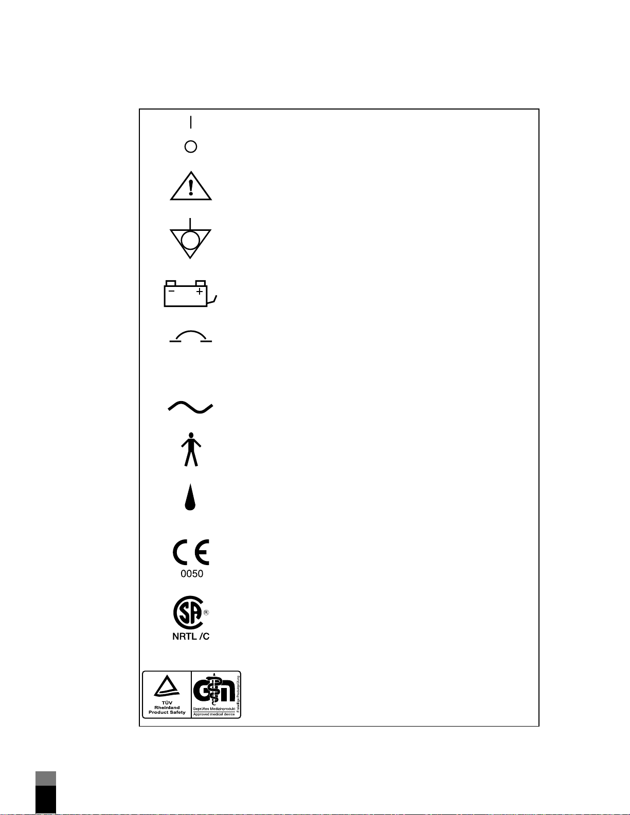
Symbols and labels
These symbols and labels appear on the 700 Series Vent ilator System:
Power switch positions per IEC 601-1. ”I” represents ON position;
“O” represents OFF position.
Refer to manual per IEC 601-1. When this symbol appears on
product, it means “Refer to documentation for information.”
Potential equalization point, per IEC 601-1
External battery connection
Circuit breaker
SN
IPX1
Serial number
ac current
Type B equipment, per IEC 601-1
Indicates the degree of protection provided by enclosure
(drip-proof).
Signifies compliance with the Medical Device Directive, 93/42/EEC.
CSA and NRTL (Nationally Recognized Testing Laboratory)
certification, gra nted by C S A
The TUV Rheinland logo sig nifies TUV Rheinland Type Test approval
to Annex III of the Medical Device Directive
vi
700 Series Ventilator System Service Manu al G-061875-00 Rev . A (11/99)
.........
..........................................................................................
.
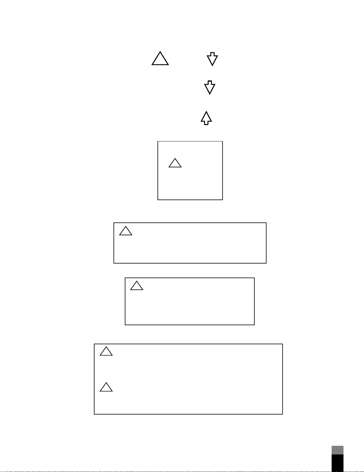
Exhaust port
Inspiratory limb
Expiratory limb
Oxygen inlet port
Air intake
connector
connector
label
connector
label
!
EXHAUST
TO
PATIENT
FROM
PATIENT
O
!
40 - 90 psi
(275 - 620 kPa)
Use 50 psi (345 kPa)
V
= 160 L/min
max
(at STPD)
2
!
WARNING:
AIR INTAKE - DO NOT OBSTRUCT. Filter located behind panel.
Replace filter every 1,000 running hours or every 3 months,
whichever occurs first. Consult operator’s manual for complete
instructions.
Cooling fan
General life support equipment warning
label
!
CAUTION:
COOLING FAN- DO NOT OBSTRUCT.
Filter located behind panel. Clean or replace filter as
required every 250 running hours or every month,
whichever occurs first. Consult operator’s manual
for complete instructions.
!
WARNING:
This ventilator is not intended to be a comprehensive monitoring device: some
types of dangerous conditions will not activate alarms. Patients on life-support
equipment should be appropriately monitored by competent medical personnel
and suitable monitoring devices.
!
WARNING:
Before use, read operator’s manual thoroughly. Before each use, check
equipment for proper operation.
label
G-061875-00 Rev. A (11/99) 700 Series Ventilator System Service Manual
vii
.............................................................................................
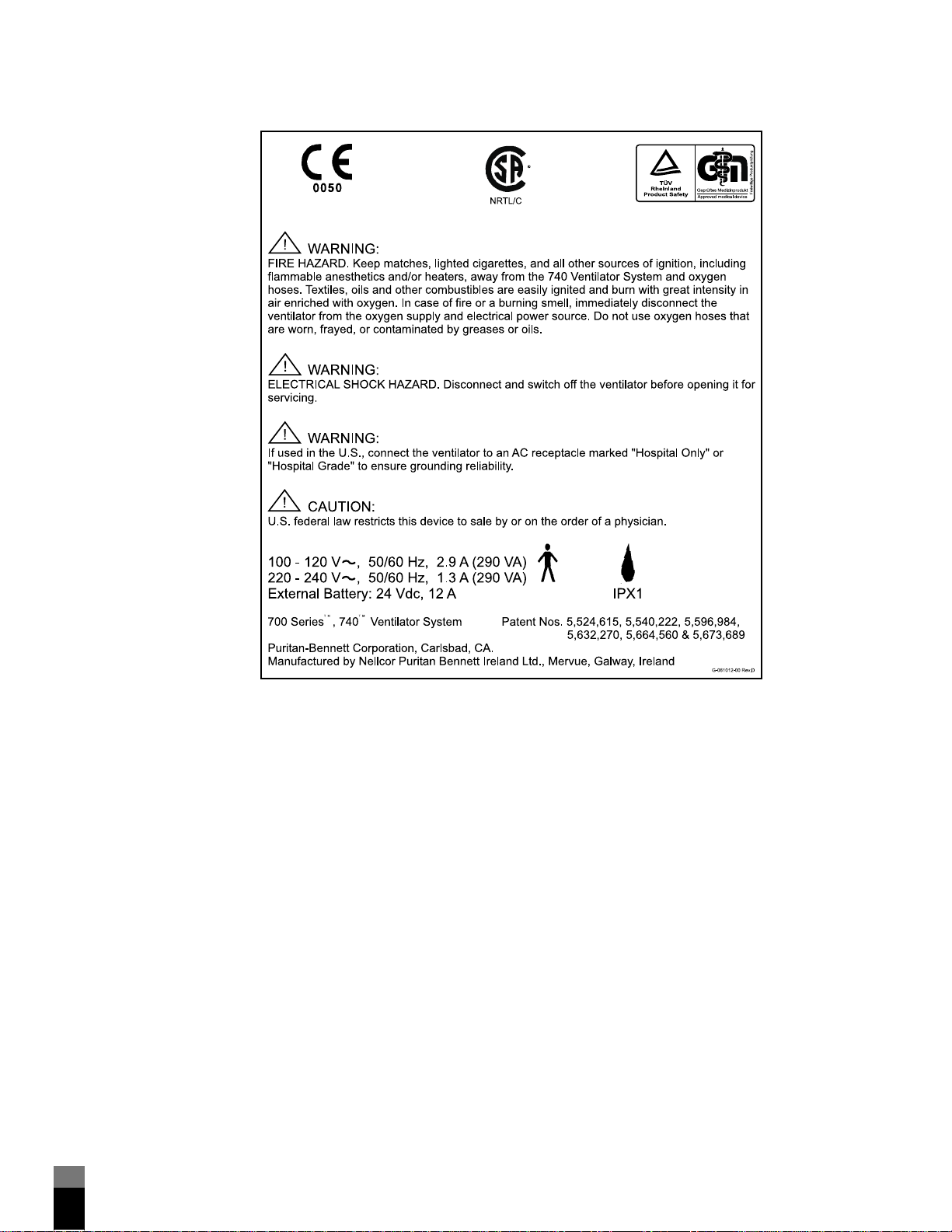
Back panel label (740)
7-00311
viii
700 Series Ventilator System Service Manu al G-061875-00 Rev . A (11/99)
.........
..........................................................................................
.
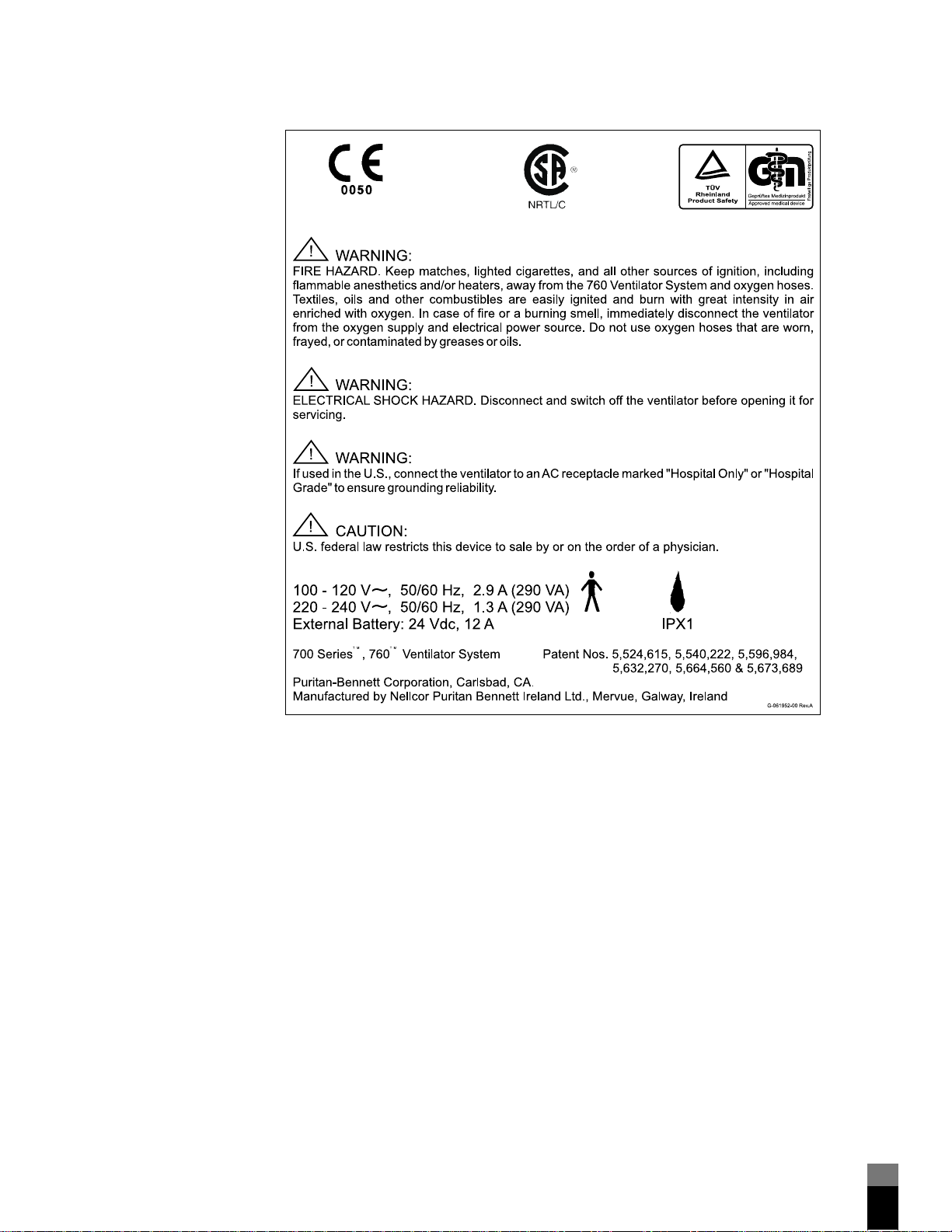
Back panel label (760)
7-00312
G-061875-00 Rev. A (11/99) 700 Series Ventilator System Se rvi c e Manual
ix
.........

.............................................................................................
x
700 Series Ventilator System Service Manu al G-061875-00 Rev . A (11/99)
.........

.
Contents
.......................................................................................
1 General information
1.1 How to use this manual. . . . . . . . . . . . . . . . . . . . . . . . . . . . . . . . . . . . . . . . . . . 1-1
1.2 Safety . . . . . . . . . . . . . . . . . . . . . . . . . . . . . . . . . . . . . . . . . . . . . . . . . . . . . . . . 1-1
1.3 General description. . . . . . . . . . . . . . . . . . . . . . . . . . . . . . . . . . . . . . . . . . . . . . 1-2
1.4 Configuration information. . . . . . . . . . . . . . . . . . . . . . . . . . . . . . . . . . . . . . . . . 1-4
1.5 Accessories . . . . . . . . . . . . . . . . . . . . . . . . . . . . . . . . . . . . . . . . . . . . . . . . . . . . 1-4
1.6 Specifications . . . . . . . . . . . . . . . . . . . . . . . . . . . . . . . . . . . . . . . . . . . . . . . . . . 1-4
1.7 Tools, Equipment, and Service Materials . . . . . . . . . . . . . . . . . . . . . . . . . . . . . . 1-9
1.8 Periodic maintenance. . . . . . . . . . . . . . . . . . . . . . . . . . . . . . . . . . . . . . . . . . . 1-14
1.9 Service kits . . . . . . . . . . . . . . . . . . . . . . . . . . . . . . . . . . . . . . . . . . . . . . . . . . . 1-15
1.10 Controls and indicators. . . . . . . . . . . . . . . . . . . . . . . . . . . . . . . . . . . . . . . . . 1-15
1.10.1 VENTILATOR SETTINGS . . . . . . . . . . . . . . . . . . . . . . . . . . . . . . . . . . . 1-18
1.10.2 PATIENT DATA . . . . . . . . . . . . . . . . . . . . . . . . . . . . . . . . . . . . . . . . . 1-24
1.10.3 VENTILATOR STATUS . . . . . . . . . . . . . . . . . . . . . . . . . . . . . . . . . . . . . 1-29
1.11 Location Of ventilator serial number . . . . . . . . . . . . . . . . . . . . . . . . . . . . . . . 1-30
1.12 Determining software revision. . . . . . . . . . . . . . . . . . . . . . . . . . . . . . . . . . . . 1-30
1.13 Service philosophy . . . . . . . . . . . . . . . . . . . . . . . . . . . . . . . . . . . . . . . . . . . . 1-30
1.14 Reference documentation . . . . . . . . . . . . . . . . . . . . . . . . . . . . . . . . . . . . . . . 1-30
2 Theory of operation
2.1 Overview of ventilator operation. . . . . . . . . . . . . . . . . . . . . . . . . . . . . . . . . . . . 2-1
2.2 Pneumatic system . . . . . . . . . . . . . . . . . . . . . . . . . . . . . . . . . . . . . . . . . . . . . . . 2-2
2.2.1 Gas Inlet System Overview . . . . . . . . . . . . . . . . . . . . . . . . . . . . . . . . . . . 2-6
2.2.2 Piston/cylinder system . . . . . . . . . . . . . . . . . . . . . . . . . . . . . . . . . . . . . 2-13
2.2.3 Inspiration manifold system . . . . . . . . . . . . . . . . . . . . . . . . . . . . . . . . . 2-20
2.2.4 Patient system . . . . . . . . . . . . . . . . . . . . . . . . . . . . . . . . . . . . . . . . . . . 2-24
2.2.5 Exhalation system. . . . . . . . . . . . . . . . . . . . . . . . . . . . . . . . . . . . . . . . . 2-27
2.2.6 PEEP/CPAP system . . . . . . . . . . . . . . . . . . . . . . . . . . . . . . . . . . . . . . . . 2-31
2.3 Electrical system . . . . . . . . . . . . . . . . . . . . . . . . . . . . . . . . . . . . . . . . . . . . . . . 2-34
2.3.1 Power assembly . . . . . . . . . . . . . . . . . . . . . . . . . . . . . . . . . . . . . . . . . . 2-38
2.3.2 Internal battery. . . . . . . . . . . . . . . . . . . . . . . . . . . . . . . . . . . . . . . . . . . 2-45
2.3.3 External battery . . . . . . . . . . . . . . . . . . . . . . . . . . . . . . . . . . . . . . . . . . 2-46
2.3.4 Pressure solenoid PCB. . . . . . . . . . . . . . . . . . . . . . . . . . . . . . . . . . . . . . 2-47
2.3.5 Controller PCB . . . . . . . . . . . . . . . . . . . . . . . . . . . . . . . . . . . . . . . . . . . 2-50
2.3.6 User interface (UI). . . . . . . . . . . . . . . . . . . . . . . . . . . . . . . . . . . . . . . . . 2-54
2.3.7 Miscellaneous electronic parts . . . . . . . . . . . . . . . . . . . . . . . . . . . . . . . 2-58
2.4 Communications option . . . . . . . . . . . . . . . . . . . . . . . . . . . . . . . . . . . . . . . . . 2-61
2.5 Motor control and drive . . . . . . . . . . . . . . . . . . . . . . . . . . . . . . . . . . . . . . . . . 2-61
2.6 Breath delivery . . . . . . . . . . . . . . . . . . . . . . . . . . . . . . . . . . . . . . . . . . . . . . . . 2-62
2.6.1 Piston initialization . . . . . . . . . . . . . . . . . . . . . . . . . . . . . . . . . . . . . . . . 2-65
2.6.2 Breath triggering . . . . . . . . . . . . . . . . . . . . . . . . . . . . . . . . . . . . . . . . . 2-66
2.6.3 Gas delivery to the patient . . . . . . . . . . . . . . . . . . . . . . . . . . . . . . . . . . 2-68
2.6.4 Exhalation and piston retraction. . . . . . . . . . . . . . . . . . . . . . . . . . . . . . 2-70
G-061875-00 Rev. A (11/99) 700 Series V en tilator System Service M a n ual
xi
.........

.......................................................................................
2.7 Power source switchover . . . . . . . . . . . . . . . . . . . . . . . . . . . . . . . . . . . . . . . . 2-76
2.8 Emergency modes . . . . . . . . . . . . . . . . . . . . . . . . . . . . . . . . . . . . . . . . . . . . . 2-78
2.8.1 Occlusion cycling mode. . . . . . . . . . . . . . . . . . . . . . . . . . . . . . . . . . . . 2-78
2.8.2 Ventilator inoperative. . . . . . . . . . . . . . . . . . . . . . . . . . . . . . . . . . . . . . 2-79
2.8.3 Safety valve open (SVO). . . . . . . . . . . . . . . . . . . . . . . . . . . . . . . . . . . . 2-80
3Self-tests
3.1 Introduction. . . . . . . . . . . . . . . . . . . . . . . . . . . . . . . . . . . . . . . . . . . . . . . . . . . 3-1
3.2 Power-on self-test (POST). . . . . . . . . . . . . . . . . . . . . . . . . . . . . . . . . . . . . . . . . 3-2
3.2.1 Structure of POST . . . . . . . . . . . . . . . . . . . . . . . . . . . . . . . . . . . . . . . . . 3-2
3.2.2 Running POST . . . . . . . . . . . . . . . . . . . . . . . . . . . . . . . . . . . . . . . . . . . . 3-2
3.2.3 How the ventilator responds to a POST error . . . . . . . . . . . . . . . . . . . . . 3-2
3.3 Short self-test (SST) . . . . . . . . . . . . . . . . . . . . . . . . . . . . . . . . . . . . . . . . . . . . . 3-6
3.4 Extended self-test (EST) . . . . . . . . . . . . . . . . . . . . . . . . . . . . . . . . . . . . . . . . . . 3-6
3.4.1 When to run . . . . . . . . . . . . . . . . . . . . . . . . . . . . . . . . . . . . . . . . . . . . . 3-6
3.4.2 Hardware requirements . . . . . . . . . . . . . . . . . . . . . . . . . . . . . . . . . . . . . 3-7
3.4.3 Running EST . . . . . . . . . . . . . . . . . . . . . . . . . . . . . . . . . . . . . . . . . . . . . 3-7
3.4.4 Troubleshooting. . . . . . . . . . . . . . . . . . . . . . . . . . . . . . . . . . . . . . . . . . 3-17
3.5 Ongoing checks . . . . . . . . . . . . . . . . . . . . . . . . . . . . . . . . . . . . . . . . . . . . . . . 3-23
4 Service and utility functions
4.1 Introduction. . . . . . . . . . . . . . . . . . . . . . . . . . . . . . . . . . . . . . . . . . . . . . . . . . . 4-1
4.1.1 Accessing the service or utilities functions . . . . . . . . . . . . . . . . . . . . . . . 4-1
4.1.2 Summary of functions . . . . . . . . . . . . . . . . . . . . . . . . . . . . . . . . . . . . . . 4-2
4.1.3 Navigating the Service and Utilities menus. . . . . . . . . . . . . . . . . . . . . . . 4-2
4.1.4 About the test and alert logs and EST test results . . . . . . . . . . . . . . . . . . 4-4
4.2 Service functions. . . . . . . . . . . . . . . . . . . . . . . . . . . . . . . . . . . . . . . . . . . . . . . . 4-4
4.2.1 Sensor data . . . . . . . . . . . . . . . . . . . . . . . . . . . . . . . . . . . . . . . . . . . . . . 4-4
4.2.2 EST (Extended self-test) . . . . . . . . . . . . . . . . . . . . . . . . . . . . . . . . . . . . . 4-8
4.2.3 Diagnostics/Calib. . . . . . . . . . . . . . . . . . . . . . . . . . . . . . . . . . . . . . . . . . 4-8
4.2.4 Review alert log: Reading the alert log . . . . . . . . . . . . . . . . . . . . . . . . . 4-26
4.2.5 Test data: Reading the test log or EST test results. . . . . . . . . . . . . . . . . 4-26
4.3 Utilities functions . . . . . . . . . . . . . . . . . . . . . . . . . . . . . . . . . . . . . . . . . . . . . . 4-27
4.3.1 Pressure format . . . . . . . . . . . . . . . . . . . . . . . . . . . . . . . . . . . . . . . . . . 4-27
4.3.2 Date and time format. . . . . . . . . . . . . . . . . . . . . . . . . . . . . . . . . . . . . . 4-27
5 Performance verification
5.1 When to run. . . . . . . . . . . . . . . . . . . . . . . . . . . . . . . . . . . . . . . . . . . . . . . . . . . 5-1
5.2 Tools, test equipment, and service materials. . . . . . . . . . . . . . . . . . . . . . . . . . . 5-2
5.3 Preliminary ventilator cleaning and inspection . . . . . . . . . . . . . . . . . . . . . . . . . 5-3
5.4 Preliminary ventilator setup . . . . . . . . . . . . . . . . . . . . . . . . . . . . . . . . . . . . . . . 5-4
5.5 Preliminary pneumatic test equipment setup . . . . . . . . . . . . . . . . . . . . . . . . . . 5-4
5.6 Performance verification procedures. . . . . . . . . . . . . . . . . . . . . . . . . . . . . . . . . 5-4
5.6.1 Electrical safety test and power-on self-test (POST) (Test 1) . . . . . . . . . . 5-5
5.6.2 Rotary encoder test (Test 2) . . . . . . . . . . . . . . . . . . . . . . . . . . . . . . . . . . 5-6
5.6.3 Battery test (Test 3) . . . . . . . . . . . . . . . . . . . . . . . . . . . . . . . . . . . . . . . . 5-6
xii
700 Series Ventilator System Service Manu al G-061875-00 Rev . A (11/99)
.........

.......................................................................................
5.6.4 Supply voltage test (Test 4) . . . . . . . . . . . . . . . . . . . . . . . . . . . . . . . . . . 5-8
5.6.5 Gas volume accuracy, breath timing, and PEEP system test (Test 5),
using the RT-200 Pneumatic Calibration Analyzer. . . . . . . . . . . . . . . . . . 5-9
5.6.6 Gas volume accuracy, breath timing, and PEEP system test (Test 5),
using the PTS 2000 and Breathlab software . . . . . . . . . . . . . . . . . . . . . 5-13
5.6.7 Extended self-test (EST) (Test 6) . . . . . . . . . . . . . . . . . . . . . . . . . . . . . . 5-17
5.6.8 Oxygen accuracy test (Test 7) using the RT-200. . . . . . . . . . . . . . . . . . 5-17
5.6.9 Oxygen accuracy test (Test 7) using the PTS 2000 . . . . . . . . . . . . . . . . 5-21
5.6.10 High pressure alarm test (Test 8) using the RT-200. . . . . . . . . . . . . . . 5-24
5.6.11 High pressure alarm test (Test 8) using the PTS 2000 . . . . . . . . . . . . . 5-25
5.6.12 Safety valve test (Test 9). . . . . . . . . . . . . . . . . . . . . . . . . . . . . . . . . . . 5-26
5.7 Troubleshooting . . . . . . . . . . . . . . . . . . . . . . . . . . . . . . . . . . . . . . . . . . . . . . . 5-27
6 Diagnostic codes
6.1 How to use this section. . . . . . . . . . . . . . . . . . . . . . . . . . . . . . . . . . . . . . . . . . . 6-1
6.2 About software errors . . . . . . . . . . . . . . . . . . . . . . . . . . . . . . . . . . . . . . . . . . . . 6-1
6.3 About ventilator status (13000 series) codes . . . . . . . . . . . . . . . . . . . . . . . . . . . 6-2
6.4 List of codes . . . . . . . . . . . . . . . . . . . . . . . . . . . . . . . . . . . . . . . . . . . . . . . . . . . 6-2
7 Alarm messages
7.1 Alarm classifications. . . . . . . . . . . . . . . . . . . . . . . . . . . . . . . . . . . . . . . . . . . . . . 7-1
7.2 Responding to alarms . . . . . . . . . . . . . . . . . . . . . . . . . . . . . . . . . . . . . . . . . . . . 7-1
8 Service and repair
8.1 Introduction . . . . . . . . . . . . . . . . . . . . . . . . . . . . . . . . . . . . . . . . . . . . . . . . . . . 8-1
8.1.1 How to use this section. . . . . . . . . . . . . . . . . . . . . . . . . . . . . . . . . . . . . . 8-1
8.1.2 General repair safety. . . . . . . . . . . . . . . . . . . . . . . . . . . . . . . . . . . . . . . . 8-1
8.1.3 General repair guidelines . . . . . . . . . . . . . . . . . . . . . . . . . . . . . . . . . . . . 8-2
8.1.4 Repair-related cleaning. . . . . . . . . . . . . . . . . . . . . . . . . . . . . . . . . . . . . . 8-3
8.1.5 Electrical cables and pneumatic tubing. . . . . . . . . . . . . . . . . . . . . . . . . . 8-3
8.1.6 Adhesive use. . . . . . . . . . . . . . . . . . . . . . . . . . . . . . . . . . . . . . . . . . . . . . 8-3
8.1.7 Electrostatic discharge control . . . . . . . . . . . . . . . . . . . . . . . . . . . . . . . . 8-4
8.1.8 Repainting and touch-up . . . . . . . . . . . . . . . . . . . . . . . . . . . . . . . . . . . . 8-5
8.1.9 Replacement part ordering. . . . . . . . . . . . . . . . . . . . . . . . . . . . . . . . . . . 8-5
8.1.10 Post-repair . . . . . . . . . . . . . . . . . . . . . . . . . . . . . . . . . . . . . . . . . . . . . . 8-5
8.2 Patient system and accessories . . . . . . . . . . . . . . . . . . . . . . . . . . . . . . . . . . . . . 8-5
8.3 Cart assembly . . . . . . . . . . . . . . . . . . . . . . . . . . . . . . . . . . . . . . . . . . . . . . . . . . 8-6
8.3.1 Removing/installing ventilator from/to cart. . . . . . . . . . . . . . . . . . . . . . . 8-6
8.3.2 Removing/installing oxygen cylinder brackets. . . . . . . . . . . . . . . . . . . . . 8-8
8.3.3 Removing/installing cylinder covers . . . . . . . . . . . . . . . . . . . . . . . . . . . . 8-9
8.3.4 Removing/installing collector vial support bracket . . . . . . . . . . . . . . . . . 8-9
8.3.5 Removing/installing humidifier support bracket . . . . . . . . . . . . . . . . . . . 8-9
8.3.6 Removing/installing basket. . . . . . . . . . . . . . . . . . . . . . . . . . . . . . . . . . . 8-9
8.3.7 Removing/installing external battery and cover . . . . . . . . . . . . . . . . . . 8-11
G-061875-00 Rev. A (11/99) 700 Series Ventilator System Se rvi c e Manual
xiii
.........

.......................................................................................
8.4 Shelf mount . . . . . . . . . . . . . . . . . . . . . . . . . . . . . . . . . . . . . . . . . . . . . . . . . . 8-12
8.4.1 Removing/installing ventilator from/to shelf mount . . . . . . . . . . . . . . . 8-12
8.4.2 Removing/installing collector vial support bracket . . . . . . . . . . . . . . . . 8-13
8.4.3 Removing/installing humidifier support bracket . . . . . . . . . . . . . . . . . . 8-13
8.5 User interface (UI) assembly (lid). . . . . . . . . . . . . . . . . . . . . . . . . . . . . . . . . . . 8-14
8.5.1 Opening and propping lid. . . . . . . . . . . . . . . . . . . . . . . . . . . . . . . . . . 8-14
8.5.2 Removing/installing lid. . . . . . . . . . . . . . . . . . . . . . . . . . . . . . . . . . . . . 8-14
8.5.3 Knob and rotary encoder. . . . . . . . . . . . . . . . . . . . . . . . . . . . . . . . . . . 8-16
8.5.4 UI display PCB . . . . . . . . . . . . . . . . . . . . . . . . . . . . . . . . . . . . . . . . . . . 8-17
8.5.5 LCD panel (message window) . . . . . . . . . . . . . . . . . . . . . . . . . . . . . . . 8-18
8.5.6 Keyboard assembly . . . . . . . . . . . . . . . . . . . . . . . . . . . . . . . . . . . . . . . 8-19
8.6 Ventilator head cabinet assembly . . . . . . . . . . . . . . . . . . . . . . . . . . . . . . . . . . 8-20
8.6.1 Oxygen adapter assembly . . . . . . . . . . . . . . . . . . . . . . . . . . . . . . . . . . 8-20
8.6.2 Options panel plate . . . . . . . . . . . . . . . . . . . . . . . . . . . . . . . . . . . . . . . 8-21
8.6.3 Communications option . . . . . . . . . . . . . . . . . . . . . . . . . . . . . . . . . . . 8-22
8.6.4 Air intake cover and filter . . . . . . . . . . . . . . . . . . . . . . . . . . . . . . . . . . . 8-27
8.6.5 Air flow thermistor assembly . . . . . . . . . . . . . . . . . . . . . . . . . . . . . . . . 8-28
8.6.6 Oxygen fitting, inspiration access panel, and air intake manifold
assembly . . . . . . . . . . . . . . . . . . . . . . . . . . . . . . . . . . . . . . . . . . . . . . . 8-28
8.6.7 Air intake filter switch . . . . . . . . . . . . . . . . . . . . . . . . . . . . . . . . . . . . . . 8-30
8.6.8 Flex arm mounting block. . . . . . . . . . . . . . . . . . . . . . . . . . . . . . . . . . . 8-31
8.6.9 Removing/installing cabinet assembly . . . . . . . . . . . . . . . . . . . . . . . . . 8-31
8.7 Oxygen regulator, oxygen solenoid, mixing manifold, and cylinder inlet
check valve . . . . . . . . . . . . . . . . . . . . . . . . . . . . . . . . . . . . . . . . . . . . . . . . . . 8-32
8.7.1 Removing oxygen regulator, oxygen solenoid, mixing manifold,
and cylinder inlet check valve . . . . . . . . . . . . . . . . . . . . . . . . . . . . . . . 8-33
8.7.2 Installing oxygen regulator, oxygen solenoid assembly, mixing
manifold, and cylinder inlet check valve. . . . . . . . . . . . . . . . . . . . . . . . 8-36
8.7.3 Oxygen regulator pressure transducer . . . . . . . . . . . . . . . . . . . . . . . . . 8-37
8.8 Inspiration manifold assembly. . . . . . . . . . . . . . . . . . . . . . . . . . . . . . . . . . . . . 8-38
8.8.1 Oxygen sensor. . . . . . . . . . . . . . . . . . . . . . . . . . . . . . . . . . . . . . . . . . . 8-38
8.8.2 Inspiration manifold thermistor . . . . . . . . . . . . . . . . . . . . . . . . . . . . . . 8-40
8.8.3 Safety valve assembly. . . . . . . . . . . . . . . . . . . . . . . . . . . . . . . . . . . . . . 8-40
8.8.4 Removing/installing inspiration manifold assembly. . . . . . . . . . . . . . . . 8-41
8.9 Exhalation assembly . . . . . . . . . . . . . . . . . . . . . . . . . . . . . . . . . . . . . . . . . . . . 8-43
8.9.1 Exhalation assembly cover . . . . . . . . . . . . . . . . . . . . . . . . . . . . . . . . . . 8-43
8.9.2 Exhalation heater and thermistor assemblies . . . . . . . . . . . . . . . . . . . . 8-44
8.9.3 Exhalation assembly. . . . . . . . . . . . . . . . . . . . . . . . . . . . . . . . . . . . . . . 8-46
8.9.4 Exhalation check valve . . . . . . . . . . . . . . . . . . . . . . . . . . . . . . . . . . . . . 8-47
8.9.5 Exhalation valve. . . . . . . . . . . . . . . . . . . . . . . . . . . . . . . . . . . . . . . . . . 8-48
8.9.6 Exhalation flow sensor assembly. . . . . . . . . . . . . . . . . . . . . . . . . . . . . . 8-48
8.10 Cable management bar, PCBs, speaker, and piezo alarm . . . . . . . . . . . . . . . 8-49
8.10.1 Speaker . . . . . . . . . . . . . . . . . . . . . . . . . . . . . . . . . . . . . . . . . . . . . . . 8-49
8.10.2 Piezo alarm . . . . . . . . . . . . . . . . . . . . . . . . . . . . . . . . . . . . . . . . . . . . 8-50
8.10.3 Pressure solenoid PCB and controller PCB . . . . . . . . . . . . . . . . . . . . . 8-50
8.10.4 Cylinder and exhalation pressure transducer autozero solenoids . . . . 8-57
8.10.5 Cable management bar . . . . . . . . . . . . . . . . . . . . . . . . . . . . . . . . . . . 8-57
xiv
700 Series Ventilator System Service Manu al G-061875-00 Rev . A (11/99)
.........

.......................................................................................
8.11 PEEP pump and reservoir. . . . . . . . . . . . . . . . . . . . . . . . . . . . . . . . . . . . . . . . 8-58
8.11.1 PEEP pump. . . . . . . . . . . . . . . . . . . . . . . . . . . . . . . . . . . . . . . . . . . . . 8-58
8.11.2 PEEP reservoir and filter. . . . . . . . . . . . . . . . . . . . . . . . . . . . . . . . . . . . 8-58
8.11.3 Exhalation solenoid. . . . . . . . . . . . . . . . . . . . . . . . . . . . . . . . . . . . . . . 8-59
8.12 Piston/cylinder and motor/encoder assemblies . . . . . . . . . . . . . . . . . . . . . . . 8-60
8.12.1 Optoswitches . . . . . . . . . . . . . . . . . . . . . . . . . . . . . . . . . . . . . . . . . . . 8-60
8.12.2 Removing/installing piston/cylinder and motor/encoder assemblies . . 8-60
8.12.3 Greasing rack . . . . . . . . . . . . . . . . . . . . . . . . . . . . . . . . . . . . . . . . . . . 8-62
8.12.4 Meshing motor pinion gear with rack. . . . . . . . . . . . . . . . . . . . . . . . . 8-62
8.13 Ventilator rear components. . . . . . . . . . . . . . . . . . . . . . . . . . . . . . . . . . . . . . 8-67
8.13.1 Main fan and filter . . . . . . . . . . . . . . . . . . . . . . . . . . . . . . . . . . . . . . . 8-67
8.13.2 Internal battery. . . . . . . . . . . . . . . . . . . . . . . . . . . . . . . . . . . . . . . . . . 8-67
8.14 Power assembly. . . . . . . . . . . . . . . . . . . . . . . . . . . . . . . . . . . . . . . . . . . . . . . 8-69
8.14.1 Power cord. . . . . . . . . . . . . . . . . . . . . . . . . . . . . . . . . . . . . . . . . . . . . 8-69
8.14.2 Removing power assembly . . . . . . . . . . . . . . . . . . . . . . . . . . . . . . . . . 8-69
8.14.3 Line filter . . . . . . . . . . . . . . . . . . . . . . . . . . . . . . . . . . . . . . . . . . . . . . 8-70
8.14.4 Circuit breaker . . . . . . . . . . . . . . . . . . . . . . . . . . . . . . . . . . . . . . . . . . 8-71
8.14.5 Power switch . . . . . . . . . . . . . . . . . . . . . . . . . . . . . . . . . . . . . . . . . . . 8-71
8.14.6 External battery harness . . . . . . . . . . . . . . . . . . . . . . . . . . . . . . . . . . . 8-72
8.14.7 Power supply . . . . . . . . . . . . . . . . . . . . . . . . . . . . . . . . . . . . . . . . . . . 8-73
8.14.8 Power supply fan . . . . . . . . . . . . . . . . . . . . . . . . . . . . . . . . . . . . . . . . 8-76
8.14.9 BBU PCB and heatsink bars. . . . . . . . . . . . . . . . . . . . . . . . . . . . . . . . . 8-77
8.15 Harnesses and wiring . . . . . . . . . . . . . . . . . . . . . . . . . . . . . . . . . . . . . . . . . . 8-78
8.15.1 Main ventilator head harness . . . . . . . . . . . . . . . . . . . . . . . . . . . . . . . 8-78
9 Parts list
9.1 How to use this parts list. . . . . . . . . . . . . . . . . . . . . . . . . . . . . . . . . . . . . . . . . . 9-1
9.2
9.3 Oxygen hose assemblies . . . . . . . . . . . . . . . . . . . . . . . . . . . . . . . . . . . . . . . . . . 9-7
9.4 Flex arm assembly. . . . . . . . . . . . . . . . . . . . . . . . . . . . . . . . . . . . . . . . . . . . . . . 9-8
9.5 Ventilator major assemblies. . . . . . . . . . . . . . . . . . . . . . . . . . . . . . . . . . . . . . . . 9-9
9.6 Cart assembly . . . . . . . . . . . . . . . . . . . . . . . . . . . . . . . . . . . . . . . . . . . . . . . . . 9-12
9.7 Shelf mounting kit. . . . . . . . . . . . . . . . . . . . . . . . . . . . . . . . . . . . . . . . . . . . . . 9-18
9.8 User interface (UI) assembly . . . . . . . . . . . . . . . . . . . . . . . . . . . . . . . . . . . . . . 9-20
9.9 Ventilator head assembly. . . . . . . . . . . . . . . . . . . . . . . . . . . . . . . . . . . . . . . . . 9-23
9.10 Oxygen hose adapters. . . . . . . . . . . . . . . . . . . . . . . . . . . . . . . . . . . . . . . . . . 9-30
9.11 Label kit . . . . . . . . . . . . . . . . . . . . . . . . . . . . . . . . . . . . . . . . . . . . . . . . . . . . 9-32
9.12 Inspiration manifold assembly . . . . . . . . . . . . . . . . . . . . . . . . . . . . . . . . . . . 9-34
9.13 Oxygen regulator and oxygen solenoid assembly . . . . . . . . . . . . . . . . . . . . . 9-36
9.14 Exhalation assembly . . . . . . . . . . . . . . . . . . . . . . . . . . . . . . . . . . . . . . . . . . . 9-38
9.15 Cable management bar, PCBs, speaker, and piezo alarm. . . . . . . . . . . . . . . . 9-41
9.16 PEEP pump and reservoir. . . . . . . . . . . . . . . . . . . . . . . . . . . . . . . . . . . . . . . . 9-46
9.17 Piston/cylinder and motor/encoder assemblies . . . . . . . . . . . . . . . . . . . . . . . 9-48
9.18 Ventilator rear components . . . . . . . . . . . . . . . . . . . . . . . . . . . . . . . . . . . . . 9-52
9.19 Power assembly . . . . . . . . . . . . . . . . . . . . . . . . . . . . . . . . . . . . . . . . . . . . . . 9-54
9.20 Power cords . . . . . . . . . . . . . . . . . . . . . . . . . . . . . . . . . . . . . . . . . . . . . . . . . 9-60
Ventilator System patient system and accessories parts list . . . . . . . . 9-3
G-061875-00 Rev. A (11/99) 700 Series Ventilator System Se rvi c e Manual
xv
.........
.......................................................................................
9.21 Tubing . . . . . . . . . . . . . . . . . . . . . . . . . . . . . . . . . . . . . . . . . . . . . . . . . . . . . 9-62
9.22 Harnesses and wiring . . . . . . . . . . . . . . . . . . . . . . . . . . . . . . . . . . . . . . . . . . 9-64
9.23 15,000-hour preventive maintenance kit . . . . . . . . . . . . . . . . . . . . . . . . . . . 9-67
9.24 30,000-hour preventive maintenance kit . . . . . . . . . . . . . . . . . . . . . . . . . . . 9-68
9.25
9.26 Service tool kit . . . . . . . . . . . . . . . . . . . . . . . . . . . . . . . . . . . . . . . . . . . . . . . 9-71
9.27 Oxygen sensor assemblies . . . . . . . . . . . . . . . . . . . . . . . . . . . . . . . . . . . . . . 9-72
9.28 Communications option. . . . . . . . . . . . . . . . . . . . . . . . . . . . . . . . . . . . . . . . 9-72
9.29
A Alphabetic part index
B Numeric parts index
Ventilator spare parts kit . . . . . . . . . . . . . . . . . . . . . . . . . . . . . . . 9-69
Ventilator assemblies . . . . . . . . . . . . . . . . . . . . . . . . . . . . . . . . . . . . . . . 9-72
xvi
700 Series Ventilator System Service Manu al G-061875-00 Rev . A (11/99)
.........

.
Figures
.......................................................................................
Figure 1-1.
Figure 1-2. Controls and indicators on
Figure 1-3. Controls and indicators on
Figure 2-1.
Figure 2-2. Pneumatic system . . . . . . . . . . . . . . . . . . . . . . . . . . . . . . . . . . . . . . . . . . . . . . . . . . . 2-3
Figure 2-3. Gas inlet system pneumatic diagram . . . . . . . . . . . . . . . . . . . . . . . . . . . . . . . . . . . . 2-6
Figure 2-4. Gas inlet system . . . . . . . . . . . . . . . . . . . . . . . . . . . . . . . . . . . . . . . . . . . . . . . . . . . . 2-7
Figure 2-5. Gas inlet system components . . . . . . . . . . . . . . . . . . . . . . . . . . . . . . . . . . . . . . . . . 2-11
Figure 2-6. Piston/cylinder system pneumatic diagram . . . . . . . . . . . . . . . . . . . . . . . . . . . . . . . 2-13
Figure 2-7. Piston/cylinder system . . . . . . . . . . . . . . . . . . . . . . . . . . . . . . . . . . . . . . . . . . . . . . 2-16
Figure 2-8. Piston/cylinder system components. . . . . . . . . . . . . . . . . . . . . . . . . . . . . . . . . . . . . 2-17
Figure 2-9. Motor/encoder pinion gear and rack . . . . . . . . . . . . . . . . . . . . . . . . . . . . . . . . . . . 2-19
Figure 2-10. Operation of optical encoder . . . . . . . . . . . . . . . . . . . . . . . . . . . . . . . . . . . . . . . . . 2-19
Figure 2-11. Inspiration manifold system pneumatic diagram . . . . . . . . . . . . . . . . . . . . . . . . . . . 2-20
Figure 2-12. Inspiration manifold system . . . . . . . . . . . . . . . . . . . . . . . . . . . . . . . . . . . . . . . . . . 2-22
Figure 2-13. Inspiration manifold system components. . . . . . . . . . . . . . . . . . . . . . . . . . . . . . . . . 2-23
Figure 2-14. Patient system pneumatic diagram . . . . . . . . . . . . . . . . . . . . . . . . . . . . . . . . . . . . . 2-25
Figure 2-15. Patient system components . . . . . . . . . . . . . . . . . . . . . . . . . . . . . . . . . . . . . . . . . . 2-26
Figure 2-16. Exhalation system pneumatic diagram . . . . . . . . . . . . . . . . . . . . . . . . . . . . . . . . . . 2-27
Figure 2-17. Exhalation system . . . . . . . . . . . . . . . . . . . . . . . . . . . . . . . . . . . . . . . . . . . . . . . . . . 2-28
Figure 2-18. Exhalation system components . . . . . . . . . . . . . . . . . . . . . . . . . . . . . . . . . . . . . . . . 2-29
Figure 2-19. PEEP/CPAP system pneumatic diagram . . . . . . . . . . . . . . . . . . . . . . . . . . . . . . . . . . 2-31
Figure 2-20. PEEP/CPAP system . . . . . . . . . . . . . . . . . . . . . . . . . . . . . . . . . . . . . . . . . . . . . . . . . 2-32
Figure 2-21. PEEP/CPAP system components . . . . . . . . . . . . . . . . . . . . . . . . . . . . . . . . . . . . . . . 2-33
Figure 2-22. Main ventilator head harness. . . . . . . . . . . . . . . . . . . . . . . . . . . . . . . . . . . . . . . . . . 2-34
Figure 2-23.
Figure 2-24. Wiring diagram. . . . . . . . . . . . . . . . . . . . . . . . . . . . . . . . . . . . . . . . . . . . . . . . . . . . 2-36
Figure 2-25. Power assembly. . . . . . . . . . . . . . . . . . . . . . . . . . . . . . . . . . . . . . . . . . . . . . . . . . . . 2-38
Figure 2-26. Power assembly harnesses . . . . . . . . . . . . . . . . . . . . . . . . . . . . . . . . . . . . . . . . . . . 2-40
Figure 2-27. Power supply/ventilator head harness . . . . . . . . . . . . . . . . . . . . . . . . . . . . . . . . . . . 2-40
Figure 2-28. Power input components . . . . . . . . . . . . . . . . . . . . . . . . . . . . . . . . . . . . . . . . . . . . 2-41
Figure 2-29. Power supply with harnesses . . . . . . . . . . . . . . . . . . . . . . . . . . . . . . . . . . . . . . . . . 2-42
Figure 2-30. BBU PCB . . . . . . . . . . . . . . . . . . . . . . . . . . . . . . . . . . . . . . . . . . . . . . . . . . . . . . . . . 2-44
Figure 2-31. BBU PCB and fan installed in power assembly . . . . . . . . . . . . . . . . . . . . . . . . . . . . . 2-44
Figure 2-32. Power supply fan . . . . . . . . . . . . . . . . . . . . . . . . . . . . . . . . . . . . . . . . . . . . . . . . . . 2-45
Figure 2-33. Internal battery . . . . . . . . . . . . . . . . . . . . . . . . . . . . . . . . . . . . . . . . . . . . . . . . . . . . 2-46
Figure 2-34. Internal battery and main fan installed in ventilator . . . . . . . . . . . . . . . . . . . . . . . . 2-46
Figure 2-35. External battery . . . . . . . . . . . . . . . . . . . . . . . . . . . . . . . . . . . . . . . . . . . . . . . . . . . 2-47
Figure 2-36. Pressure solenoid PCB . . . . . . . . . . . . . . . . . . . . . . . . . . . . . . . . . . . . . . . . . . . . . . . 2-49
Figure 2-37. Pressure solenoid and controller PCBs installed . . . . . . . . . . . . . . . . . . . . . . . . . . . . 2-49
Figure 2-38. Controller PCB. . . . . . . . . . . . . . . . . . . . . . . . . . . . . . . . . . . . . . . . . . . . . . . . . . . . . 2-51
Ventilator Systems . . . . . . . . . . . . . . . . . . . . . . . . . . . . . . . . . . . . . . . . . . 1-3
Ventilator keyboard . . . . . . . . . . . . . . . . . . . . . . . . 1-16
Ventilator keyboard . . . . . . . . . . . . . . . . . . . . . . . . 1-17
Ventilator Systems . . . . . . . . . . . . . . . . . . . . . . . . . . . . . . . . . . . . . . . . . . 2-2
Ventilator System block diagram. . . . . . . . . . . . . . . . . . . . . . . . . . . . . . . 2-35
G-061875-00 Rev. A (11/99) 700 Series V en tilator System Service M a n ual
xvii
.........

.......................................................................................
Figure 2-39. EPROM . . . . . . . . . . . . . . . . . . . . . . . . . . . . . . . . . . . . . . . . . . . . . . . . . . . . . . . . . 2-51
Figure 2-40. User interface (UI) . . . . . . . . . . . . . . . . . . . . . . . . . . . . . . . . . . . . . . . . . . . . . . . . . 2-55
Figure 2-41. UI display PCB (740 shown) . . . . . . . . . . . . . . . . . . . . . . . . . . . . . . . . . . . . . . . . . . 2-56
Figure 2-42. 4-line x 20-character LCD panel (message window) . . . . . . . . . . . . . . . . . . . . . . . . 2-56
Figure 2-43. Keyboard assembly (740 shown) . . . . . . . . . . . . . . . . . . . . . . . . . . . . . . . . . . . . . . 2-57
Figure 2-44. Rotary encoder with knob . . . . . . . . . . . . . . . . . . . . . . . . . . . . . . . . . . . . . . . . . . . 2-57
Figure 2-45. Speaker . . . . . . . . . . . . . . . . . . . . . . . . . . . . . . . . . . . . . . . . . . . . . . . . . . . . . . . . . 2-58
Figure 2-46. Piezo alarm . . . . . . . . . . . . . . . . . . . . . . . . . . . . . . . . . . . . . . . . . . . . . . . . . . . . . . 2-58
Figure 2-47. Speaker, piezo alarm, air flow thermistor assembly, and air intake filter
switch installed . . . . . . . . . . . . . . . . . . . . . . . . . . . . . . . . . . . . . . . . . . . . . . . . . . . 2-59
Figure 2-48. Main fan with cover, filter, and guard . . . . . . . . . . . . . . . . . . . . . . . . . . . . . . . . . . 2-59
Figure 2-49. Air flow thermistor assembly . . . . . . . . . . . . . . . . . . . . . . . . . . . . . . . . . . . . . . . . . 2-60
Figure 2-50. Air flow thermistor assembly installed on air intake manifold . . . . . . . . . . . . . . . . . 2-60
Figure 2-51. Air intake filter switch . . . . . . . . . . . . . . . . . . . . . . . . . . . . . . . . . . . . . . . . . . . . . . . 2-61
Figure 2-52. Motor control and drive . . . . . . . . . . . . . . . . . . . . . . . . . . . . . . . . . . . . . . . . . . . . . 2-62
Figure 2-53. Breath cycle for a VCV breath without PEEP . . . . . . . . . . . . . . . . . . . . . . . . . . . . . . 2-63
Figure 2-54. Breath cycle for a PCV breath . . . . . . . . . . . . . . . . . . . . . . . . . . . . . . . . . . . . . . . . . 2-64
Figure 2-55. Piston initialization . . . . . . . . . . . . . . . . . . . . . . . . . . . . . . . . . . . . . . . . . . . . . . . . . 2-65
Figure 2-56. Pneumatic diagram of breath triggering. . . . . . . . . . . . . . . . . . . . . . . . . . . . . . . . . 2-67
Figure 2-57. Breath triggering and breath delivery parameters . . . . . . . . . . . . . . . . . . . . . . . . . . 2-68
Figure 2-58. Pneumatic diagram of gas delivery . . . . . . . . . . . . . . . . . . . . . . . . . . . . . . . . . . . . . 2-69
Figure 2-59. Pneumatic diagram of exhalation and piston retraction (low-flow oxygen
solenoid energized) . . . . . . . . . . . . . . . . . . . . . . . . . . . . . . . . . . . . . . . . . . . . . . . . 2-72
Figure 2-60. Exhalation and piston retraction parameters. . . . . . . . . . . . . . . . . . . . . . . . . . . . . . 2-73
Figure 2-61. Air and oxygen flow during retraction . . . . . . . . . . . . . . . . . . . . . . . . . . . . . . . . . . 2-74
Figure 2-62. Piston movement for volumes <250 ml . . . . . . . . . . . . . . . . . . . . . . . . . . . . . . . . . 2-75
Figure 2-63. Power source switchover. . . . . . . . . . . . . . . . . . . . . . . . . . . . . . . . . . . . . . . . . . . . . 2-77
Figure 2-64. Safety valve open pneumatic diagram . . . . . . . . . . . . . . . . . . . . . . . . . . . . . . . . . . 2-81
Figure 4-1. Navigating the Service and Utilities menus . . . . . . . . . . . . . . . . . . . . . . . . . . . . . . . . 4-3
Figure 4-3. Oxygen regulator pressure transducer calibration setup . . . . . . . . . . . . . . . . . . . . . 4-13
Figure 4-4. PEEP pump calibration setup . . . . . . . . . . . . . . . . . . . . . . . . . . . . . . . . . . . . . . . . . 4-16
Figure 4-5. P
Figure 4-6. Adjusting oxygen regulator pressure. . . . . . . . . . . . . . . . . . . . . . . . . . . . . . . . . . . . 4-22
Figure 4-7. Test and alert log format. . . . . . . . . . . . . . . . . . . . . . . . . . . . . . . . . . . . . . . . . . . . . 4-26
Figure 5-1. Power supply/reference voltage test connector J2 on pressure solenoid PCB . . . . . . 5-8
Figure 5-2. RT-200 Setup for Test 5 . . . . . . . . . . . . . . . . . . . . . . . . . . . . . . . . . . . . . . . . . . . . . 5-10
Figure 5-3. PTS 2000 Setup for Test 5 . . . . . . . . . . . . . . . . . . . . . . . . . . . . . . . . . . . . . . . . . . . 5-13
Figure 8-1. Removing ventilator attachment screws from cart . . . . . . . . . . . . . . . . . . . . . . . . . . 8-6
Figure 8-2. Removing ventilator from cart . . . . . . . . . . . . . . . . . . . . . . . . . . . . . . . . . . . . . . . . . 8-7
Figure 8-3. Removing oxygen cylinder brackets . . . . . . . . . . . . . . . . . . . . . . . . . . . . . . . . . . . . . 8-8
Figure 8-4. Removing collector vial and Fisher & Paykel Humidifier support brackets from cart . 8-9
Figure 8-5. Removing Hudson RCI humidifier bracket assembly . . . . . . . . . . . . . . . . . . . . . . . . 8-10
Figure 8-6. Removing basket . . . . . . . . . . . . . . . . . . . . . . . . . . . . . . . . . . . . . . . . . . . . . . . . . . 8-10
xviii
700 Series Ventilator System Service Manual G-061875-00 Rev. A (11/99)
gain equalization setup . . . . . . . . . . . . . . . . . . . . . . . . . . . . . . . . . . . . . . . . 4-18
e Pcyl
.........

.......................................................................................
Figure 8-7. Removing external battery cover . . . . . . . . . . . . . . . . . . . . . . . . . . . . . . . . . . . . . . 8-11
Figure 8-8. Removing collector vial and humidifier support brackets from shelf mount . . . . . . . 8-12
Figure 8-9. Removing shelf mount from ventilator . . . . . . . . . . . . . . . . . . . . . . . . . . . . . . . . . . 8-13
Figure 8-10. Lid raised . . . . . . . . . . . . . . . . . . . . . . . . . . . . . . . . . . . . . . . . . . . . . . . . . . . . . . . . 8-15
Figure 8-11. Propping the lid . . . . . . . . . . . . . . . . . . . . . . . . . . . . . . . . . . . . . . . . . . . . . . . . . . . 8-16
Figure 8-12. UI removed . . . . . . . . . . . . . . . . . . . . . . . . . . . . . . . . . . . . . . . . . . . . . . . . . . . . . . . 8-17
Figure 8-13. Removing LCD panel . . . . . . . . . . . . . . . . . . . . . . . . . . . . . . . . . . . . . . . . . . . . . . . 8-18
Figure 8-14. Spacers on keyboard assembly . . . . . . . . . . . . . . . . . . . . . . . . . . . . . . . . . . . . . . . . 8-19
Figure 8-15. Oxygen adapter assemblies disassembled . . . . . . . . . . . . . . . . . . . . . . . . . . . . . . . . 8-20
Figure 8-16. Options panel plate . . . . . . . . . . . . . . . . . . . . . . . . . . . . . . . . . . . . . . . . . . . . . . . . 8-21
Figure 8-17.
Figure 8-18. Removing Communications option assembly . . . . . . . . . . . . . . . . . . . . . . . . . . . . . 8-23
Figure 8-19. Disassembling Communications option assembly (remote alarm, nebulizer,
Figure 8-20. Removing harnesses/connectors from Communications option assembly . . . . . . . . 8-25
Figure 8-21. Removing the Communications option PCB assembly from the
Figure 8-22. Inspiration access panel . . . . . . . . . . . . . . . . . . . . . . . . . . . . . . . . . . . . . . . . . . . . . 8-27
Figure 8-23. Air flow thermistor assembly installed . . . . . . . . . . . . . . . . . . . . . . . . . . . . . . . . . . . 8-28
Figure 8-24. Inspiration access panel removed . . . . . . . . . . . . . . . . . . . . . . . . . . . . . . . . . . . . . . 8-29
Figure 8-25. Air intake manifold assembly disassembled . . . . . . . . . . . . . . . . . . . . . . . . . . . . . . . 8-30
Figure 8-26. Flex arm mounting block . . . . . . . . . . . . . . . . . . . . . . . . . . . . . . . . . . . . . . . . . . . . 8-31
Figure 8-27. Removing oxygen regulator/oxygen solenoid assembly . . . . . . . . . . . . . . . . . . . . . 8-33
Figure 8-28. Separating the oxygen solenoid assembly from the oxygen regulator . . . . . . . . . . . 8-34
Figure 8-29. Cylinder check valves . . . . . . . . . . . . . . . . . . . . . . . . . . . . . . . . . . . . . . . . . . . . . . . 8-35
Figure 8-30. Oxygen regulator pressure transducer . . . . . . . . . . . . . . . . . . . . . . . . . . . . . . . . . . 8-37
Figure 8-31. Inspiration manifold assembly . . . . . . . . . . . . . . . . . . . . . . . . . . . . . . . . . . . . . . . . 8-39
Figure 8-32. Oxygen sensor with and without adapter . . . . . . . . . . . . . . . . . . . . . . . . . . . . . . . . 8-39
Figure 8-33. Removing inspiration manifold assembly . . . . . . . . . . . . . . . . . . . . . . . . . . . . . . . . 8-42
Figure 8-34. Exhalation assembly cover . . . . . . . . . . . . . . . . . . . . . . . . . . . . . . . . . . . . . . . . . . . 8-43
Figure 8-35. Exhalation assembly installed . . . . . . . . . . . . . . . . . . . . . . . . . . . . . . . . . . . . . . . . . 8-44
Figure 8-36. Exhalation heater and thermistor assemblies . . . . . . . . . . . . . . . . . . . . . . . . . . . . . . 8-45
Figure 8-37. Threading thermistor through flow sensor heater clip . . . . . . . . . . . . . . . . . . . . . . . 8-46
Figure 8-38. Exhalation assembly, speaker, and piezo alarm mounting . . . . . . . . . . . . . . . . . . . . 8-47
Figure 8-39. Exhalation check valve in position . . . . . . . . . . . . . . . . . . . . . . . . . . . . . . . . . . . . . . 8-48
Figure 8-40. Cable management bar, PCBs, speaker, and piezo alarm . . . . . . . . . . . . . . . . . . . . 8-49
Figure 8-41. Pressure solenoid PCB tube connectors . . . . . . . . . . . . . . . . . . . . . . . . . . . . . . . . . . 8-51
Figure 8-42. Controller PCB component locations . . . . . . . . . . . . . . . . . . . . . . . . . . . . . . . . . . . 8-53
Figure 8-43. Removing and installing EPROMs . . . . . . . . . . . . . . . . . . . . . . . . . . . . . . . . . . . . . . 8-56
Figure 8-44. PEEP pump and reservoir . . . . . . . . . . . . . . . . . . . . . . . . . . . . . . . . . . . . . . . . . . . . 8-59
Figure 8-45. Piston/cylinder assembly installed . . . . . . . . . . . . . . . . . . . . . . . . . . . . . . . . . . . . . . 8-60
Figure 8-46. Greasing rack . . . . . . . . . . . . . . . . . . . . . . . . . . . . . . . . . . . . . . . . . . . . . . . . . . . . . 8-62
Figure 8-47. Gear mesh procedure: Pushing rack to end stop at delivered end . . . . . . . . . . . . . . 8-63
Figure 8-48. Gear mesh procedure: Positioning motor encoder . . . . . . . . . . . . . . . . . . . . . . . . . 8-64
Figure 8-49. Gear mesh procedure: Fasteners installed but not locked . . . . . . . . . . . . . . . . . . . . 8-64
Figure 8-50. Gear mesh procedure: Tightening screws to slightly compress spring washers . . . . 8-65
nurse call, and serial port hardware) . . . . . . . . . . . . . . . . . . . . . . . . . . . . . . . . . . . . 8-24
option plate assembly . . . . . . . . . . . . . . . . . . . . . . . . . . . . . . . . . . . . . . . . . . . . . . . 8-26
Communications option panel . . . . . . . . . . . . . . . . . . . . . . . . . . . . . . . . 8-22
G-061875-00 Rev. A (11/99) 700 Series Ventilator System Se rvi c e Manual
xix
.........

.......................................................................................
Figure 8-51. Gear mesh procedure: Pushing rack from end to end . . . . . . . . . . . . . . . . . . . . . . . 8-66
Figure 8-52. Ventilator rear components . . . . . . . . . . . . . . . . . . . . . . . . . . . . . . . . . . . . . . . . . . 8-68
Figure 8-53. Power assembly pulled out . . . . . . . . . . . . . . . . . . . . . . . . . . . . . . . . . . . . . . . . . . 8-70
Figure 8-54. Line filter, circuit breaker, and power switch connections . . . . . . . . . . . . . . . . . . . . 8-70
Figure 8-55. Power supply input terminal connections . . . . . . . . . . . . . . . . . . . . . . . . . . . . . . . . 8-71
Figure 8-56. Power supply output terminal connections . . . . . . . . . . . . . . . . . . . . . . . . . . . . . . 8-72
Figure 8-57. Power assembly removed . . . . . . . . . . . . . . . . . . . . . . . . . . . . . . . . . . . . . . . . . . . . 8-74
Figure 8-58. Power supply baffle. . . . . . . . . . . . . . . . . . . . . . . . . . . . . . . . . . . . . . . . . . . . . . . . . 8-75
Figure 8-59. BBU PCB and power supply fan. . . . . . . . . . . . . . . . . . . . . . . . . . . . . . . . . . . . . . . . 8-76
Figure 8-60. Heatsink bars and conductive strips on BBU PCB. . . . . . . . . . . . . . . . . . . . . . . . . . . 8-77
Figure 8-61. BBU PCB attaching hardware . . . . . . . . . . . . . . . . . . . . . . . . . . . . . . . . . . . . . . . . . 8-78
Figure 8-62. Main ventilator head harness installed . . . . . . . . . . . . . . . . . . . . . . . . . . . . . . . . . . 8-79
Figure 8-63. Main ventilator head harness connections . . . . . . . . . . . . . . . . . . . . . . . . . . . . . . . 8-79
Figure 9-1.
Figure 9-2. Oxygen hose assemblies . . . . . . . . . . . . . . . . . . . . . . . . . . . . . . . . . . . . . . . . . . . . . 9-7
Figure 9-3. Flex arm assembly . . . . . . . . . . . . . . . . . . . . . . . . . . . . . . . . . . . . . . . . . . . . . . . . . . 9-8
Figure 9-4. Ventilator major assemblies . . . . . . . . . . . . . . . . . . . . . . . . . . . . . . . . . . . . . . . . . . 9-10
Figure 9-5. Cart assembly. . . . . . . . . . . . . . . . . . . . . . . . . . . . . . . . . . . . . . . . . . . . . . . . . . . . . 9-15
Figure 9-6. Shelf mounting kit . . . . . . . . . . . . . . . . . . . . . . . . . . . . . . . . . . . . . . . . . . . . . . . . . 9-19
Figure 9-7. User interface (UI) assembly . . . . . . . . . . . . . . . . . . . . . . . . . . . . . . . . . . . . . . . . . . 9-22
Figure 9-8. Ventilator head assembly . . . . . . . . . . . . . . . . . . . . . . . . . . . . . . . . . . . . . . . . . . . . 9-27
Figure 9-9. Oxygen hose adapters . . . . . . . . . . . . . . . . . . . . . . . . . . . . . . . . . . . . . . . . . . . . . . 9-31
Figure 9-10. Label kit . . . . . . . . . . . . . . . . . . . . . . . . . . . . . . . . . . . . . . . . . . . . . . . . . . . . . . . . . 9-33
Figure 9-11. Inspiration manifold assembly. . . . . . . . . . . . . . . . . . . . . . . . . . . . . . . . . . . . . . . . . 9-35
Figure 9-12. Oxygen regulator and oxygen solenoid assembly . . . . . . . . . . . . . . . . . . . . . . . . . 9-37
Figure 9-13. Exhalation assembly . . . . . . . . . . . . . . . . . . . . . . . . . . . . . . . . . . . . . . . . . . . . . . . . 9-39
Figure 9-14. Cable management bar, PCBs, speaker, and piezo alarm . . . . . . . . . . . . . . . . . . . . 9-43
Figure 9-15. Controller PCB component locations . . . . . . . . . . . . . . . . . . . . . . . . . . . . . . . . . . . 9-44
Figure 9-16. Pressure solenoid PCB component locations . . . . . . . . . . . . . . . . . . . . . . . . . . . . . . 9-44
Figure 9-17. PEEP pump and reservoir . . . . . . . . . . . . . . . . . . . . . . . . . . . . . . . . . . . . . . . . . . . . 9-47
Figure 9-18. Piston/cylinder and motor/encoder assemblies . . . . . . . . . . . . . . . . . . . . . . . . . . . . 9-49
Figure 9-19. Ventilator rear components . . . . . . . . . . . . . . . . . . . . . . . . . . . . . . . . . . . . . . . . . . 9-53
Figure 9-20. Power assembly . . . . . . . . . . . . . . . . . . . . . . . . . . . . . . . . . . . . . . . . . . . . . . . . . . . 9-57
Figure 9-21. BBU PCB component locations . . . . . . . . . . . . . . . . . . . . . . . . . . . . . . . . . . . . . . . . 9-59
Figure 9-22. Power cords . . . . . . . . . . . . . . . . . . . . . . . . . . . . . . . . . . . . . . . . . . . . . . . . . . . . . . 9-61
Figure 9-23. Tubing . . . . . . . . . . . . . . . . . . . . . . . . . . . . . . . . . . . . . . . . . . . . . . . . . . . . . . . . . . 9-63
Figure 9-24. Wiring diagram. . . . . . . . . . . . . . . . . . . . . . . . . . . . . . . . . . . . . . . . . . . . . . . . . . . . 9-65
Figure 9-25. 15,000-hour preventive maintenance kit . . . . . . . . . . . . . . . . . . . . . . . . . . . . . . . . 9-67
Figure 9-26. 30,000-hour preventive maintenance kit. . . . . . . . . . . . . . . . . . . . . . . . . . . . . . . . . 9-68
Ventilator System . . . . . . . . . . . . . . . . . . . . . . . . . . . . . . . . . . . . . . . . . . 9-5
xx
700 Series Ventilator System Service Manual G-061875-00 Rev. A (11/99)
.........
.
Tables
.......................................................................................
Table 1-1: Specifications . . . . . . . . . . . . . . . . . . . . . . . . . . . . . . . . . . . . . . . . . . . . . . . . . . . . . . . 1-4
Table 1-2: Tools, equipment, and service materials . . . . . . . . . . . . . . . . . . . . . . . . . . . . . . . . . . . 1-9
Table 1-3: Schedule of periodic maintenance . . . . . . . . . . . . . . . . . . . . . . . . . . . . . . . . . . . . . . 1-14
Table 1-4: Service kits . . . . . . . . . . . . . . . . . . . . . . . . . . . . . . . . . . . . . . . . . . . . . . . . . . . . . . . . 1-15
Table 1-5:
Table 1-6:
Table 1-7:
Table 2-1: Pneumatic component data . . . . . . . . . . . . . . . . . . . . . . . . . . . . . . . . . . . . . . . . . . . . 2-4
Table 2-2: NVRAM contents . . . . . . . . . . . . . . . . . . . . . . . . . . . . . . . . . . . . . . . . . . . . . . . . . . . 2-52
Table 2-3: Changes to current settings in occlusion cycling mode . . . . . . . . . . . . . . . . . . . . . . . 2-78
Table 2-4: Safety valve open causes and indications . . . . . . . . . . . . . . . . . . . . . . . . . . . . . . . . . . 2-80
Table 3-1: Self-tests . . . . . . . . . . . . . . . . . . . . . . . . . . . . . . . . . . . . . . . . . . . . . . . . . . . . . . . . . . 3-1
Table 3-2: POST routines . . . . . . . . . . . . . . . . . . . . . . . . . . . . . . . . . . . . . . . . . . . . . . . . . . . . . . . 3-4
Table 3-3: Hardware requirements for EST . . . . . . . . . . . . . . . . . . . . . . . . . . . . . . . . . . . . . . . . . . 3-7
Table 3-4: EST prompts . . . . . . . . . . . . . . . . . . . . . . . . . . . . . . . . . . . . . . . . . . . . . . . . . . . . . . . . 3-8
Table 3-5: Key functions during EST . . . . . . . . . . . . . . . . . . . . . . . . . . . . . . . . . . . . . . . . . . . . . 3-10
Table 3-6: Prompts during EST testing . . . . . . . . . . . . . . . . . . . . . . . . . . . . . . . . . . . . . . . . . . . . 3-11
Table 3-7: EST completion status . . . . . . . . . . . . . . . . . . . . . . . . . . . . . . . . . . . . . . . . . . . . . . . . 3-12
Table 3-8: EST tests . . . . . . . . . . . . . . . . . . . . . . . . . . . . . . . . . . . . . . . . . . . . . . . . . . . . . . . . . . 3-13
Table 3-9: EST troubleshooting . . . . . . . . . . . . . . . . . . . . . . . . . . . . . . . . . . . . . . . . . . . . . . . . . 3-17
Ventilator keyboards: VENTILATOR SETTINGS . . . . . . . . . . . . . . . . . . . . . 1-19
Ventilator keyboards: PATIENT DATA . . . . . . . . . . . . . . . . . . . . . . . . . . . . 1-24
Ventilator keyboards: VENTILATOR STATUS . . . . . . . . . . . . . . . . . . . . . . . 1-29
Table 4-1: Service functions . . . . . . . . . . . . . . . . . . . . . . . . . . . . . . . . . . . . . . . . . . . . . . . . . . . . . 4-2
Table 4-2: Utilities menu functions . . . . . . . . . . . . . . . . . . . . . . . . . . . . . . . . . . . . . . . . . . . . . . . 4-2
Table 4-3: Pressure sensors . . . . . . . . . . . . . . . . . . . . . . . . . . . . . . . . . . . . . . . . . . . . . . . . . . . . . 4-5
Table 4-4: Temperature sensors . . . . . . . . . . . . . . . . . . . . . . . . . . . . . . . . . . . . . . . . . . . . . . . . . . 4-6
Table 4-5: Battery/BBU sensors . . . . . . . . . . . . . . . . . . . . . . . . . . . . . . . . . . . . . . . . . . . . . . . . . . 4-6
Table 4-6: UI/HW sensors . . . . . . . . . . . . . . . . . . . . . . . . . . . . . . . . . . . . . . . . . . . . . . . . . . . . . . 4-7
Table 4-7: Pressure sol sensors . . . . . . . . . . . . . . . . . . . . . . . . . . . . . . . . . . . . . . . . . . . . . . . . . . . 4-7
Table 4-8: Other data . . . . . . . . . . . . . . . . . . . . . . . . . . . . . . . . . . . . . . . . . . . . . . . . . . . . . . . . . 4-7
Table 4-9: Performing calibrations/Updating NVRAM Constants . . . . . . . . . . . . . . . . . . . . . . . . . 4-9
Table 5-1: When to run performance verification . . . . . . . . . . . . . . . . . . . . . . . . . . . . . . . . . . . . . 5-1
Table 5-2: Test equipment required for performance verification . . . . . . . . . . . . . . . . . . . . . . . . . 5-2
Table 5-3: Pressure solenoid PCB test connector (J2) voltages . . . . . . . . . . . . . . . . . . . . . . . . . . . 5-9
Table 6-1: Diagnostic codes . . . . . . . . . . . . . . . . . . . . . . . . . . . . . . . . . . . . . . . . . . . . . . . . . . . . . 6-3
Table 7-1: How the ventilator responds to alarm conditions . . . . . . . . . . . . . . . . . . . . . . . . . . . . 7-1
Table 7-2: Alarm messages . . . . . . . . . . . . . . . . . . . . . . . . . . . . . . . . . . . . . . . . . . . . . . . . . . . . . 7-2
Table 9-1: Abbreviations used in parts list . . . . . . . . . . . . . . . . . . . . . . . . . . . . . . . . . . . . . . . . . . 9-1
G-061875-00 Rev. A (11/99) 700 Series V en tilator System Service M a n ual
xxi
.........

.......................................................................................
xxii
700 Series Ventilator System Service Manual G-061875-00 Rev. A (11/99)
.........

.
anual Name:
700 Seri
l
art Rev Date: G-061875-00 Rev. A (11/99)
es Ventilator System Service Manua
SECTION
General information 1
1
.......................................................................................
This section provides introductory information on the Nellcor Puritan Bennett
700 Series Ventilator System. It contains a description of the ventilator, including
specifications, required tools and test equipmen t , schedule of maintenance, and
controls and indicators.
1.1 How to use this manual
The 700 Series Ventilator System Service Manual is intended to be used in conjunction
with the 700 Series Ventilator System Operator’s Manual. Both parts are needed for
field repair of the ventilator.
In several cases, however, similar information is contained in both manuals:
• Refer to the “Maintenance” appendix of the Operator’s Manual for operator
maintenance of filters and the patient system. Refer to the “Service and repair”
section of the Service Manual for maintenance activities performed by the service
technician.
• Refer to the “Self-tests” section of the Operator’s Manual or this manual for
instructions on running short self-test (SST) and extended self-test (EST). This
manual also provides EST troubleshooting information for the qualified service
technician.
1.2 Safety
• The “Part numbers” appendix of the Operator’s Manual contains ordering
information for patient system parts. Refer to the “Parts list” section of the
Service Manual for complete part ordering information.
Warning
• To p revent personal injury or death, do not attempt an y ventilator service while
a patient or other person is connected to the ventilator.
• To prevent disease transmission, use personal protective equipment when
handling contaminated bacterial filters or other patient accessories. Use
Cavicide to kill bloodborne pathogens, as required.
Ventilator maintenance may involve exposure to hazardous materials, equipment,
and conditions such as: possible electrical shock; pressurized gas; transmittable
diseases; and fire, which could result from an oxygen-enriched en vironment and
easily ignitable material. Before servicing the 70 0 Series Ventilator System, be awar e
of possible hazards and necessary precautions to be taken.
• Familiarize yourself with the warnings and caut ions on the ventilator labels
and in related publicatio n s, includin g th is manual. Also familiarize yourself
with any warnings and cautions associated with the service equip ment and
materials being used, as well as those posted in the facility where the ventilator
is serviced.
G-061875-00 Rev. A (11/99) 700 Series Ventilator System Se rvi c e Manual
1-1

1 General information
.......................................................................................
• Use any applicable personal protective equipment and adhere to the applicable
warnings and cautions.
• Be aware of the safet y standards and consi de ra t ions specific to your
situation. Safety standards may vary with international, federal, state, and local
regulatory agencies. When in doubt, consult material safety data sheets;
environmental, health, and safety professionals; and regulatory affairs
specialists. In addition, many facilities and institutions may have their own
special safety considerations.
• Be sure the ventilator passes the performance verification (Section 5) before
it is retur n e d to operation after being serviced. The performance verification
ensures the product’s safety in addition to its functional integrity.
1.3 General description
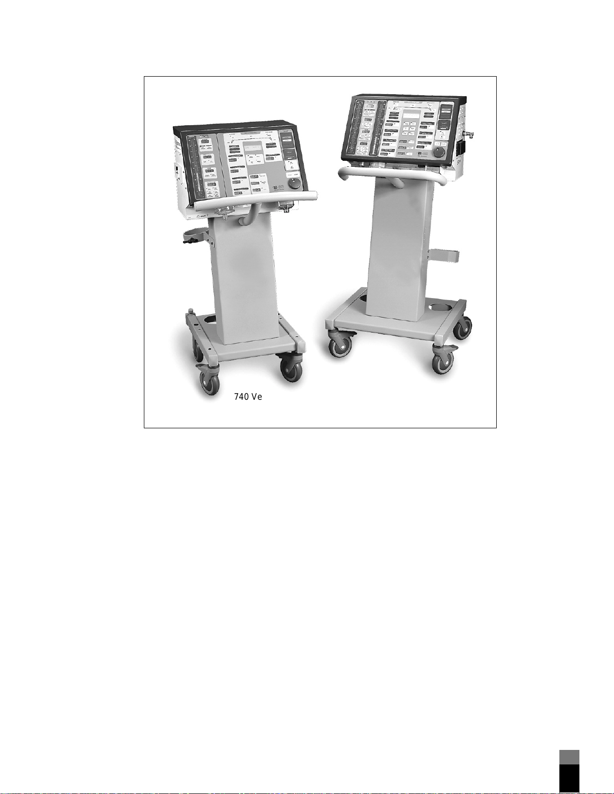
The 700 Series Ventilato r System (including the 740 and 760 Ventilators) provides
respiratory support for a wide range of pediatric to adult patients for a wide variety
of clinical conditions. The ventilator’s mixing technique allows it to ventilate
critically ill patients at adjustable oxygen concentrations without the need for a
blender, compressor, or hospital-grade wall air.
The 700 Series Ventilator System can be mains or battery powered. Each ventilator
includes two microcontrollers: one for breath delivery (which controls ventilation),
and one for the user interface (which monitors ventilator and patient data). Each
microcontroller verifies that the other is functioning properly. Using two
independent microcontrollers in this fashion prevents a single fault from causing a
simultaneous failure of controlling and monitoring functions.
The 700 Series Ventilator System supplies mandatory or spontaneous breaths with a
piston-based pneumatic system. Mandatory breaths can be volume con trol ventilat ion
(VCV, available on 740 and 760 Ventilators) or pressure control ventilation (PCV,
available on the 760 Ventilator only). VCV delivers breaths to the patient at a preset
tidal volume, peak flow, waveform, and oxygen concentration at a minimum
respiratory rate. PCV delivers breaths to the pa tient at a pr eset insp iratory pressure,
I:E ratio or inspiratory time, rise time factor (how quickly inspiratory pressure rises
to achieve the set inspiratory pressure), and oxygen concentration at a minimum
respiratory rate. A spontaneous breath allows the patient inspiratory flows of up to
300 L/min, with or without pressure support ventilation (PSV). On the 760 V e ntilator ,
you can set the rise time f actor a nd exha lation flow sensit ivit y (t hat is, the point a t
which the ventilator cycles from inspiration to exhalation) in PSV.
The ventilator begins apnea ventilation if no patient- or operator-initiated breath is
delivered within the operator-selected apnea interval. Apnea ventilation is available
in all modes (for ventilators equipped with software Rev. J or later). On the 740
Ventilator, only VCV breaths are available in apnea ventilation. On the 760
Ventilator, VCV or PCV breaths are available in apnea ventilation.
1-2
700 Series Ventilator System Service Manu al G-061875-00 Rev . A (11/99)
.........
General information 1
.......................................................................................
760 Ventilator
740 Ventilator
Ventilator System
Figure 1-1. 700 Series Ventilator Systems
Ventilator System
7-00122
G-061875-00 Rev. A (11/99) 700 Series Ventilator System Se rvi c e Manual
1-3
.........
1 General information
.......................................................................................
1.4 Configuration information
The 700 Series Ventilator System is available in a variety of versions, intended to
meet differing needs and regulations throughout the world. The major differences
in configuration among ventilators are listed below:
• Language. Keyboard (user interface) and other ventilator labeling available in
assorted languages.
• Electrical requirements. Available in 110 V and 230 V.
• Power cord. A variety of plug ends available.
• Oxygen fitting and hose. Available in DISS (diameter index safety standar d)
male and female, NIST (non-interchangeable screw thread), Australian type, Air
Liquide, and Dräger.
• Mounting. Cart or shelf mount available.
• Accessories. Ventilators may have the accessories listed in Section 1.5.
1.5 Accessories
The following accessories are either required or can be used with the ventilator.
V entil ator breat hing circuit . A variety of reusable Nellcor Puritan Bennett cir cuits,
adult and pediatric, with and without water traps, and with and without heated
wire, is available. Contact your Nellcor Puritan Bennett representative. In addition,
other breathing circuits may be used with t he ventila tor, provided they ensure that
the ventilator breathing system meets the specifications stated in Table 1-1 (see
Results of ventilator breathing system testing).
Humidifica tion device. The 700 Series Ventilator supports use of an optional
humidification device, inc luding a heated humi difier , heat and moi sture exchanger
(HME), or heated wire. A Fisher & Paykel MR730 Humidifier is available for the
ventilator. Mounting brackets are available for the Fisher & Paykel humidifiers and
the Hudson RCI ConchaTherm Humidifier.
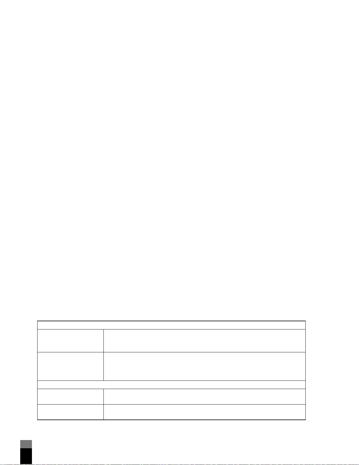
1.6 Specifications
Ventilator specifications are listed in Table 1-1.
Table 1-1: Specifications
Physical characteris t ics
Weight Ventilator only: 30 kg (66 lb)
Cart only: 18 kg (40 lb)
External battery: 12.75 kg (28 lb)
Dimensions Ventilator only: 378 mm high x 515 mm wide x 370 mm deep
(14.9 in. high x 20.3 in. wide x in. 14.6 in. deep)
Ventilator and cart: 1255 mm high x 515 mm wide x 370 mm deep
(49.4 in. high x 20.3 in. wide x 14.6 in. deep)
Environmental requirements
Temperature Operating: 5 to 45°C (41 to 113°F) at 10 to 95% relative humidity
Storage: -40 to 60°C (-40 to 140°F) at 10 to 95% relative humidity
Atmospheric pressure Operating: 8.7 to 16.0 psi (600 to 1100 hPa)
Storage: 7.3 to 16.0 psi (500 to 1100 hPa)
1-4
700 Series Ventilator System Service Manu al G-061875-00 Rev . A (11/99)
.........

General information 1
.......................................................................................
Table 1-1: Specifications (continued)
Altitude Operating: Up to 4570 m (15,000 ft)
Storage: Up to 15,240 m (50,000 ft)
Storage Maintain under conditions listed above. Remove batteries from ventilator before
storage. See “Electrical specifications, Battery shelf life when charge is not
maintained” for battery life details.
Pneumat ic specif ications
Oxygen inlet supply Pressure: 40 to 90 psi (275 to 620 kPa)
Flow: Maximum of 160 L/min at standard temperature and pressure, dry (STPD)
Fitting type: DISS male, DISS female, NIST, Air Liquide, Australian type, or Dräger
(depending on country and configuration)
Oxygen regulator bleed: Up to 3 L/min
Warning
Due to excessive restriction of the Air Liquide, Australian, and Dräger hose
assemblies, reduced FIO
psi (345 kPa) are employed. Make sure oxygen inlet pressure is ³ 50 psi (345
kPa) when using these hose assemblies, to maintain correct FIO
Connectors Inspiratory limb connector: ISO 22-mm conical male
Expiratory limb connector: ISO 22-mm conical female
Gas exhaust port: ISO 30-mm conical
Gas mixing system Range of delivery to the patient: Up to 300 L/min for pressure support ventilation
(PSV) spontaneous breaths or pressure control ventilation (PCV) mandat ory breaths;
3 to 150 L/min for mandatory or assisted volume control ventilation (VCV) breaths.
Leakage from one gas system to another: Not applicable (no high-pressure air
source)
Design pressure: 50 psi (345 kPa)
Operating pressure range: 40 to 90 psi (275 to 620 kPa)
Maximum limited
pressure
Maximum ventilating
pressure
92 cmH
A dedicated backup circuit opens the safety valve if system pressure exceeds
115 cmH
89 cmH2O (89 hPa) for VCV breaths or 80 cmH2O (80 hPa) for PSV breaths and PCV
breaths (including PEEP ), ens ur e d by HIGH PRESSURE limit.
O (92 hPa)
2
O (113 hPa).
2
levels may result when oxygen inlet pressures < 50
2
levels.
2
G-061875-00 Rev. A (11/99) 700 Series Ventilator System Se rvi c e Manual
1-5
.........
1 General information
.......................................................................................
Table 1-1: Specifications (continued)
Results of ventilator
breathing system testing
(using circuits identified
for use with
Ventilator)
Resistance ranges:
Adult circuits:
Inspiratory resistance at 60 L/min: 4.8 to 5.7 cmH
2.0 cmH
Expiratory resistance at 60 L/min: 1.6 to 2.2 cmH
4.6 cmH
Pediatric circuits:
Inspiratory resistance at 30 L/min: 1.7 to 3.0 cmH
2.8 cmH
Expiratory resistance at 30 L/min: 0.8 to 1.0 cmH
2.7 cmH
O maximum at 0 cmH2O CPAP.
2
O maximum at 0 cmH2O CPAP.
2
O maximum at 0 cmH2O CPAP.
2
O maximum at 0 cmH2O CPAP.
2
O (ventilator powered off),
2
O (ventilator powered off),
2
O (ventilator powered off),
2
O (ventilator powered off),
2
NOTE:
The circuits identified for use with the
ventilator breathing system does not exceed the EN 794-1 values for
maximum resistance (both inspiratory and expiratory), which are as follows:
Adult: 60 L/min, 6 hPa (6 cmH
Compliance range of recommended breathing circuits: 2.40 to 3.33 ml/cmH2O
Internal volume: Not applicable. The
volume losses due to gas compressibility (that is, automatic compliance
compensation), subject to a maximum delivered volume of 2.5 L.
O); Pediatric: 30 L/min, 6 hPa (6 cmH2O).
2
Ventil ator ensure that the
Ventilator automatically adjusts for
NOTE:
• To ensure that compliance compensation functions correctly, the user must run
SST or EST with the circuit configured as intended for use on the patient.
• Ventilator breathing circuit testing specifications are ba sed on the recommended
configurations shown in the
.
Electrical specifications
Power supply Input range: 100 to 120 V ac nominal (110 V units), 220 to 240 V ac nominal
(230 V units), 50/60 Hz, 2.9 A (110 V units) or 1.3 A (230 V units), 290 VA
Mains fuse: 10 A, 250 V, medium time lag, high (H) breaking capacity, 6 x 32 mm
(meets IEC and CSA standards). (A circuit breaker in the power assembly opens when
current draw exceeds 4 A.)
Earth leakage current At 100 to 120 V ac operation: less than 300 mA
At 220 to 240 V ac operation: less than 500 mA
(Includes ventilator, power cord, and internal and external batteries)
Enclosure leakage current Less than 50 mA in normal condition (all units)
Less than 300 mA in single fault condition at 100-120 V AC operation
Less than 500 mA in single fault condition at 220-240 V AC operation
Ground resistance < 0.1 W (excluding power cord); < 0.2 W (including power cord)
1-6
700 Series Ventilator System Service Manu al G-061875-00 Rev . A (11/99)
.........
General information 1
.......................................................................................
Table 1-1: Specifications (continued)
Internal battery 24 V dc, 7 Ah
Operating time (for a new, fully charged battery at 20°C and sea level):
• Approximately 2.5 hours under nominal conditions
(nominal conditions: tidal volume 0.6 L, respiratory rate 15/min,
PEEP/CPAP 5 cmH
30 cmH
• Approximately 2 hours under extreme conditions
(extreme conditions: tidal volume 1.2 L, respiratory rate 15/min,
PEEP/CPAP 15 cmH
average peak pressure 64 cmH
Recharge time: 2.5 to 3 hours in ventilator
Charges automatically while ventilator is connected to ac power and power switch is
on (including standby mo de)
Charge level indicated on user interface
External battery 24 V dc, 17 Ah
Operating time (for a new, fully charged battery at 20°C and sea level):
• Approximately 7 hours under nominal conditions
(See internal battery for definition of nominal conditions.)
• Approximately 5.5 hours under extreme conditions
(See internal battery for definition of extreme conditions.)
Recharge time: 7.5 to 8 hours in ventilator (3 to 4 hours using optional battery
charger)
Charges automatically while ventilator is connected to ac power and the power
switch is on (including standby mode)
Battery charge levels available under Battery info menu function
Battery shelf life when
charge is not maintained
Ideally internal and external batteries should be stored in a cool, dry place. If the
batteries are stored
• At 0 to 20°C (32 to 68°F): 12 months
• At 21 to 30°C (69 to 86°F): 9 months
• At 31 to 40°C (87 to 104°F): 5 months
• At 41 to 50°C (105 to 122°F): 2.5 months
O, average mean pressure 8 cmH2O)
2
O, peak flow 60 L/min, plateau 0 s; average peak pressure
2
O, peak flow 60 L/min, plateau 0 s;
2
O, average mean pressure 24 cmH2O)
2
maintaining charge, typical shelf life is as follows:
NOTE:
• If you plan to store the ventilator for longer than 6 months, remove batteries
before storage. Replace the batteries before using the ventilator again.
• Battery life specifications are approximate. To ensure maximum battery life,
maintain full charge and minimize the number of complete discharges.
Serial communications DB9 male connector
Lets computer access ventilator data. Used to upload/download service data and to
perform other communications functions.
Alarm volume Minimum (level 1): 74 dBA at 1 m
Maximum (level 5): 88 dBA at 1 m
Measuring and display devices
Mean airway pressure Sensing position: Exhalation limb
Range: 0 to 99 cmH
Type: Silicon solid state
Peak pressure Sensing position: Exhalation limb
Range: 0 to 140 cmH
Type: Silicon solid state
G-061875-00 Rev. A (11/99) 700 Series Ventilator System Se rvi c e Manual
O (0 to 99 hPa)
2
O (0 to 140 hPa)
2
1-7
.........
1 General information
.......................................................................................
Table 1-1: Specifications (continued)
Plateau pressure
(
Ventilator only)
PEEP/CPAP pressure
(
Ventilator only)
Rate Sensing position: Microprocessor
I:E ratio Sensing position: Microprocessor
Inspiratory time
(
Ventilator only)
Exhaled tidal volume Sensing position: Exhalation limb
Total minute volume Sensing position: Exhalation limb
Delivered volume
(
Ventilator only)
Spontaneous minute
volume
(
Ventilator only)
sensor Sensing position: Inspiration manifold
FIO
2
Sensing position: Exhalation limb
Range: 0 to 140 cmH
Type: Silicon solid state
Sensing position: Exhalation limb
Range: 0 to 140 cmH
Type: Silicon solid state
Range: 1 to 500 breaths/min
Type: Calculated from inspiratory and expiratory time measurements
Range: 1:99.9 to 9.9:1
Type: Calculated from inspiratory and expiratory time measurements
Sensing position: Microprocessor
Range: 0.1 to 9.9 s
Type: Inspiratory time measurement
Range: 0 to 9 L
Type: Differential pressure pneumotach
Range: 0 to 99 L
Type: Differential pressure pneumotach
Sensing position: Exhalation limb
Range: 0 to 3000 ml
Type: Differential pressure pneumotach
Sensing position: Exhalation limb
Range: 0 to 99 L
Type: Calculated from expiratory flow measurements
Range: 18 to 109 %
Type: Galvanic cell
Sensor life: 2 years, nominal. (Actual life depends on operating environment;
operation at higher temperature or FIO
O (0 to 140 hPa)
2
O (0 to 140 hPa)
2
levels will result in shorter sensor life.)
2
1-8
NOTE:
To achieve compliance with the more rigid requirements for oxygen
monitoring (as set forth in ISO 7767), Nellcor Puritan Bennett recommends
using an external monitor that meets that standard.
Service specifications
Self-test capabilities Automatic power-on self-test (POST): Verifies integrity of electronics.
Short self-test (SST): An abbreviated version of EST to be run by the operator.
Characterizes system leaks and system/tubing compliance.
Extended self-test (EST): Lets the t echnician thoroughly t est the ope rational integrity
of the ventilator , both electronics and p neumatics. Tests can also be run individually ,
in diagnostic EST mode.
Automatic, ongoing softwa re and ha r dw are c he cks .
Bacteria filter efficiency Inspiratory and expiratory filters (disposable and reusable): 99.97% retention of 0.3
mm particles at 100 L/min.
Languages Software and user labeling available in Dutch, English, French, German, Italian,
Japanese, Polish, Portuguese, Russian, or Spanish.
700 Series Ventilator System Service Manu al G-061875-00 Rev . A (11/99)
.........
 Loading...