

MA lighting SCANCOMMANDER User Manual

SCANCOMMANDER
User´s Manual
Version 4.31h
Januar 2009

MA Lighting Technology GmbH . Dachdeckerstr. 16 . D-97297 Waldbüttelbrunn . Fax: + 49 9 31 4 97 94 29 . www.malighting.de
22
22
2
Contents
1. Introduction (Version 4.31).............................................................. 5
1.1 General remarks ........................................................................................ 5
1.2 Specifications and extras ........................................................................... 6
1.3 Installation .................................................................................................. 6
2. Setup ............................................................................................. 7
2.1 Top menu ................................................................................................... 7
2.2 Lamp type .................................................................................................. 8
2.3 DMX output addresses ............................................................................... 9
2.4 Movement direction on DMX mode ........................................................... 10
2.5 Initializing of stage ................................................................................... 11
3. Direct access ............................................................................... 13
3.1 Scan groups and brightness fader ............................................................ 13
3.2 Basic scan functions ................................................................................ 14
3.2.1 Tuning with the encoder .................................................................... 14
3.2.2 Programming of presets .................................................................... 15
3.2.3 Playback of presets .......................................................................... 16
3.3 Movements .............................................................................................. 18
3.3.1 Movement on direct DMX or on stage calculation .............................. 18
3.3.2 Changing the movement mode .......................................................... 19
3.3.3 Transforming memories to a new stage ............................................. 20
3.3.4 Trackball and Mouse ......................................................................... 21
3.3.5 Followspot mode ............................................................................... 21
3.3.6 Circle mode ....................................................................................... 22
3.3.7 Movement speed ............................................................................... 23
4. Memories ..................................................................................... 24
4.1 Programming of basic memories .............................................................. 24
4.2 Playback memories ................................................................................. 26
4.2.1 Playback with programmed x-fade time and trigpoint ......................... 26
4.2.2 Playback with new x-fade time .......................................................... 26
4.2.3 Playback with manual x-fade ............................................................. 26
4.2.4 Freezing of single channels ............................................................... 27
4.2.5 Display of Memory Names ................................................................ 28
4.3 Selective memories .................................................................................. 29
4.3.1 Programming of selective memories .................................................. 29
4.3.2 Playback of selective memories ........................................................ 30
4.4 Modifying of memories ............................................................................. 31
4.4.1 Changing names and parameters ...................................................... 31
4.4.2 Changing matrix and data ................................................................. 31
4.4.3 Copying memories ............................................................................ 32

ScancommanderScancommander
ScancommanderScancommander
Scancommander
eMail: info@malighting.de . Tel.: + 49 9 31 4979 40 . User's Manual Scancommander
33
33
3
5. Chaser ......................................................................................... 33
5.1 Programming of chasers .......................................................................... 33
5.1.1 New chaser steps ............................................................................. 33
5.1.2 Programming chaser parameters ...................................................... 34
5.1.3 Insert or delete chaser steps ............................................................. 34
5.2 Playback chasers .................................................................................... 35
5.2.1 Enable Chaser .................................................................................. 35
5.3 Modifying a chaser program ..................................................................... 36
5.3.1 Changing names and parameters ...................................................... 36
5.3.2 Changing sequence of steps ............................................................. 37
5.3.3 Changing step matrix and levels ........................................................ 39
6. Sequences ................................................................................... 40
6.1 Programming of sequences ...................................................................... 40
6.1.1 New sequence steps ......................................................................... 40
6.2 Playback of sequences ............................................................................ 43
6.2.1 Playback of a sequence by GO button .............................................. 43
6.2.2 Playback of a sequence with adjusted step rate ................................ 44
6.2.3 Playback of a sequence triggered by sound input .............................. 44
6.2.4 Manual x-fade between sequence steps ............................................ 44
6.2.5 Playback of a sequence with programmed STEP MODE ................... 45
6.2.6 Enable Sequence .............................................................................. 45
6.2.7 Sequence playback menu ................................................................. 46
6.3 Modifying a sequence .............................................................................. 47
6.3.1 Changing sequence step times ......................................................... 47
6.3.2 Changing step sequence and STEP MODES .................................... 48
6.3.3 Changing step matrix and levels ........................................................ 50
6.3.4 Recalling a memory or chaser as step of a sequence ....................... 51
7. REMOTE ..................................................................................... 52
7.1 Remote via Touchboard ............................................................................ 53
7.1.1 Input signal ....................................................................................... 53
7.1.2 Assigning board functions ................................................................. 53
7.2 Remote via DMX input .............................................................................. 54
7.2.1 Input signal ....................................................................................... 54
7.2.2 Assigning board functions ................................................................. 54
7.3 MIDI ......................................................................................................... 55
7.3.1 Choosing the MIDI channel ................................................................ 55
7.3.2 MIDI data format of the Scancommander ........................................... 55
7.4 Master-Slave Operation ........................................................................... 56
7.4.1 Installation ......................................................................................... 56
7.4.2 Starting the couple mode .................................................................. 56
7.4.3 Working on master-slave mode ......................................................... 56
7.5 SMPTE TIME CODE ................................................................................ 57
7.5.1 Time Code Network Technics ............................................................ 57
7.5.2 Live recording of a Time Code show .................................................. 58
7.5.3 Time Code Playback ......................................................................... 60
7.5.4 Modifying a Time Code program ........................................................ 61
7.6 The Scancommander Extension Unit ....................................................... 63

MA Lighting Technology GmbH . Dachdeckerstr. 16 . D-97297 Waldbüttelbrunn . Fax: + 49 9 31 4 97 94 29 . www.malighting.de
44
44
4
8. Dimmer and color changers ......................................................... 64
8.1 Assigning EXTRA channels .................................................................. 64
8.2 Direct access to EXTRA channels ........................................................ 64
8.3 EXTRA groups and brightness master .................................................. 65
8.4 EXTRA presets .................................................................................... 65
8.5 EXTRA channels in memories .............................................................. 66
9. Utilities ......................................................................................... 67
9.1 Display index ........................................................................................... 67
9.2 Storage of programs ................................................................................. 68
9.2.1 Backup on to memory card ............................................................... 68
9.3 Clearing programs .................................................................................... 70
9.4 Keyswitch ................................................................................................ 70
9.5 Macros ..................................................................................................... 71
9.5.1 Programming macros ........................................................................ 71
9.5.2 Macro user examples ........................................................................ 72
10. Inputs and outputs ....................................................................... 73
11. Defining your own Scans ............................................................ 75
Index ................................................................................................ 79
Fixture Library: ................................................................................. 83
Appendix 1:...................................................................................... 87
Appendix 2:.................................................................................... 124
Controlling "TRACKSPOT" ........................................................................... 124
Controlling "INTELLABEAM" ........................................................................ 125
Controlling "Cyberlight" ................................................................................ 127
Safety instructions .......................................................................... 128
Declaration of Confirmity ................................................................ 129

ScancommanderScancommander
ScancommanderScancommander
Scancommander
eMail: info@malighting.de . Tel.: + 49 9 31 4979 40 . User's Manual Scancommander
55
55
5
1. Introduction (Version 4.31)
1.1 General remarks
The MA SCANCOMMANDER features perfect and easy control of most DMX
512 compatible moving lights and multifunctional fixtures. Up to 16 units can
be controlled simultaneously.
Main features of the MA SCANCOMMANDER:
- Access to colours, gobos etc. via labelled buttons.
- Programming of selective scenes with - for example - fixed positions but
new colours.
- Transformation of all programs to different stages and different types of
fixtures.
- Followspot via Trackball with several different fixtures.
- Slow fades with freely selectable trigpoint for colours, gobos etc.
- Direct access to all functions during running scenes.
- Fader for direct control of brightness.
- Remote inputs for touchboards, DMX 512, MIDI Sound and SMPTE Time
Code.
- Unlimited number of fixtures by docking several MA SCANCOMMANDERS.
- Simultaneous control of different types of lighting fixtures.
- Additional 96 channels for dimming or color changers.
Chapter 2 describes the set up, which has to be followed step by step:
Choosing lamp type, giving DMX starting address and initializing the stage.
Chapter 3 to 6 describe the direct access to single functions and the
programming of scenes.
Appendix 1 lists the types of fixtures, which can be interfaced to the
MA SCANCOMMANDER.
When you see ">>...." in this menu, there will be further explanations on this
subject. The index at the end makes it easy to find certain subjects.
To be involved in the update service, please fill out the registration
card at the end of the manual.
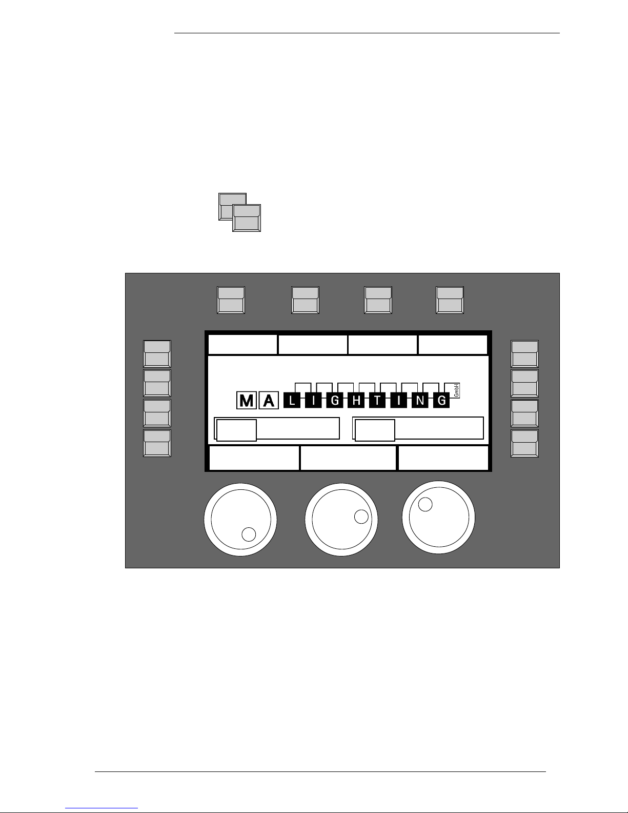
MA Scancommander
basic features

MA Lighting Technology GmbH . Dachdeckerstr. 16 . D-97297 Waldbüttelbrunn . Fax: + 49 9 31 4 97 94 29 . www.malighting.de
66
66
6
Trackball,
Computermouse
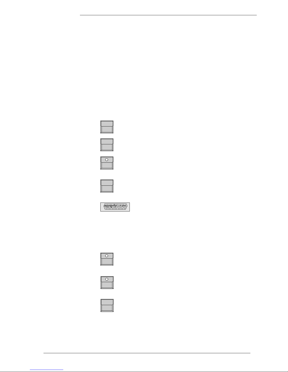
1.3 Installation
230 Volt, 50 Hz via Euro plug.
or (as option)
110 Volt, 60 Hz
According to USITT DMX 512 (1990) protocol. The output is opto insulated and
even better than RS 485 or RS 422. The pins in the 5 pin XLR plug are: Pin 1:
ground, Pin 2: Data-, Pin 3: Data+ (Pin 4 and 5: not used)
Other in- and outputs see chapter 9.
Powersupply
DMX 512 output
1.2 Specifications and extras
The basic MA SCANCOMMANDER is delivered as a 19" version with 1
desklamp. With this configuration it can perform all functions except labelling
your scenes and presets in the display. There is a list of options available that
will fit your needs.
Makes it easy to control movements. All Atari compatible trackballs or mice
can be used. Note: PC compatible mice cannot be used !!
Enables you to label your programs. Any PC-MF keyboard will work. American
keyboards may cause some problems by exchanging different letters.
(>>Memory Names, Preset Names)
The keyboard, offered by MA, can be mounted in a drawer underneath the
SCANCOMMANDER
Wooden sides and a front armrest are available.
All programs can be stored on a memory card in addition to the internal
storage. Cards from 32 to 256 kilobyte, type ITT STAR CARD S-RAM can be
used.
Backup cue card
Board housing
Keyboard drawer
Keyboard
ScancommanderScancommander
ScancommanderScancommander
Scancommander
eMail: info@malighting.de . Tel.: + 49 9 31 4979 40 . User's Manual Scancommander
77
77
7
2. Setup
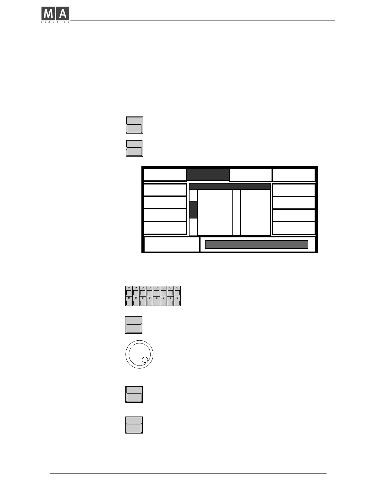
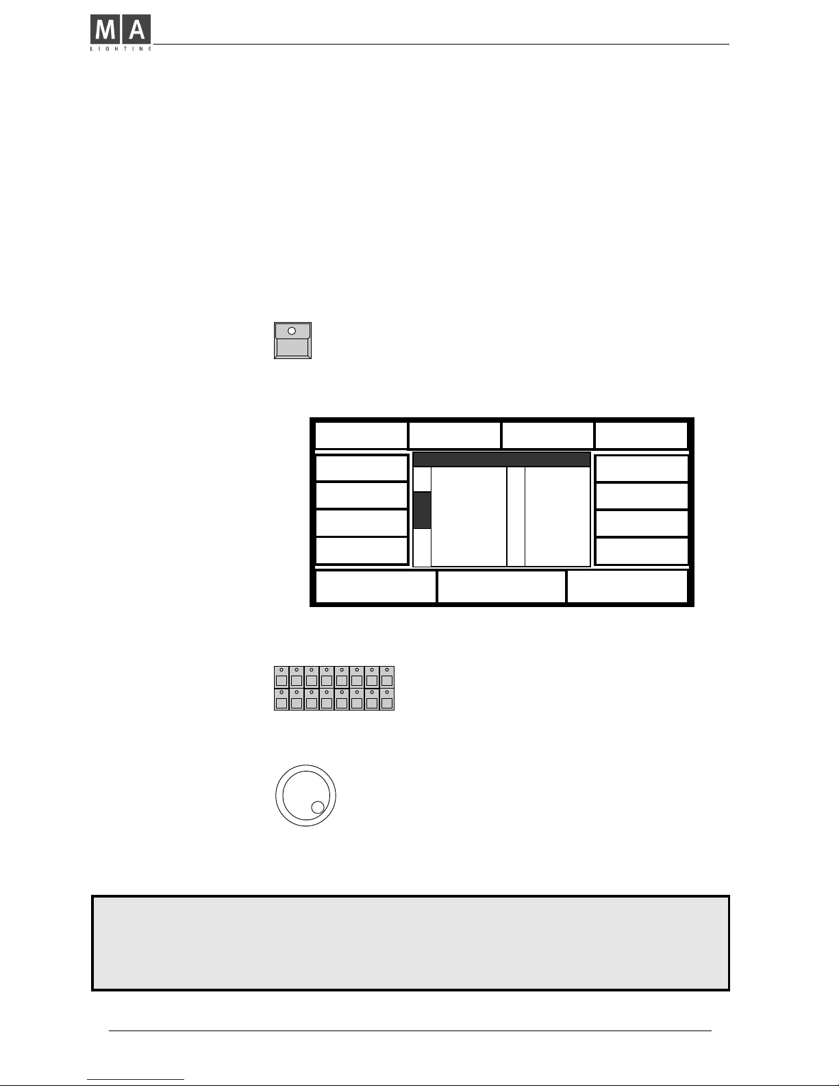
2.1 Top menu
QUIT button (2x)
Starting point for all operations is the TOP MENU. To
go back to the TOP MENU during any operation
press Quit button 2 x.
Top Menu
SETUP
PRESET
BACKUP REMOTE
14 : 50 : 17
01 / 16 / 97
DATE:TIME:
RUNNING FADE
+/- 00 %
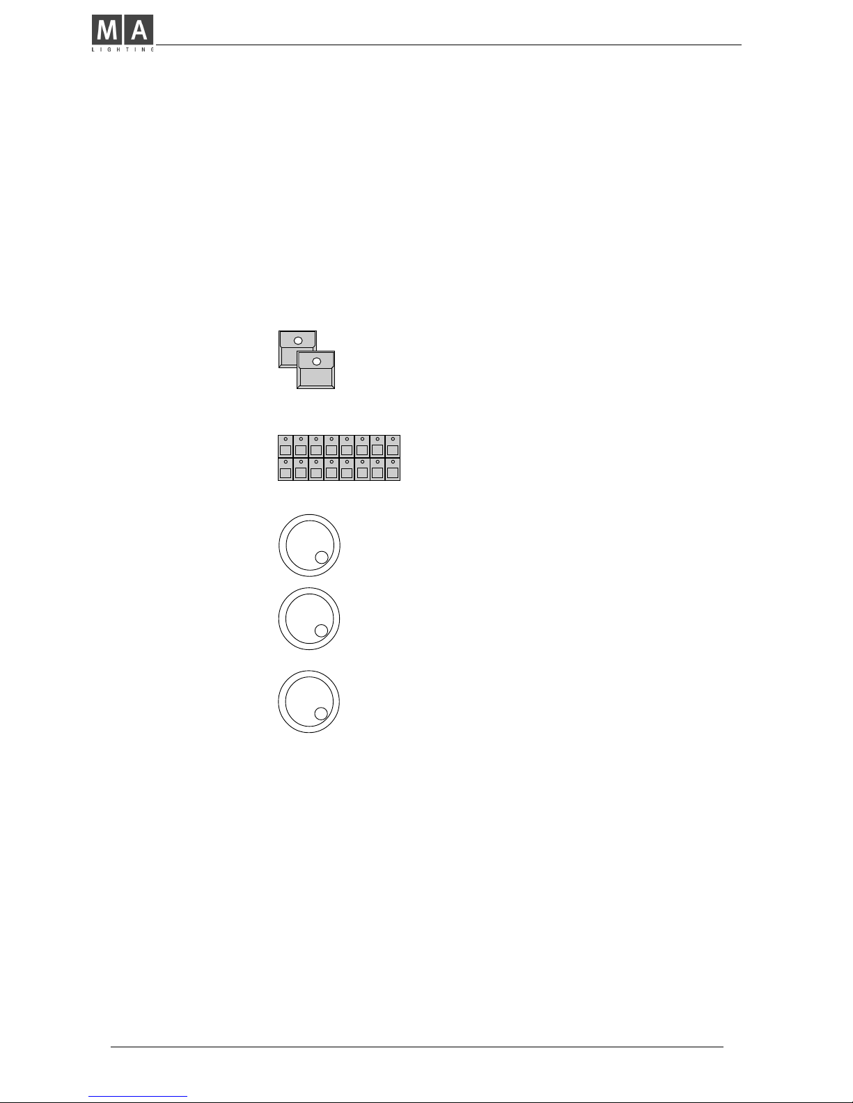
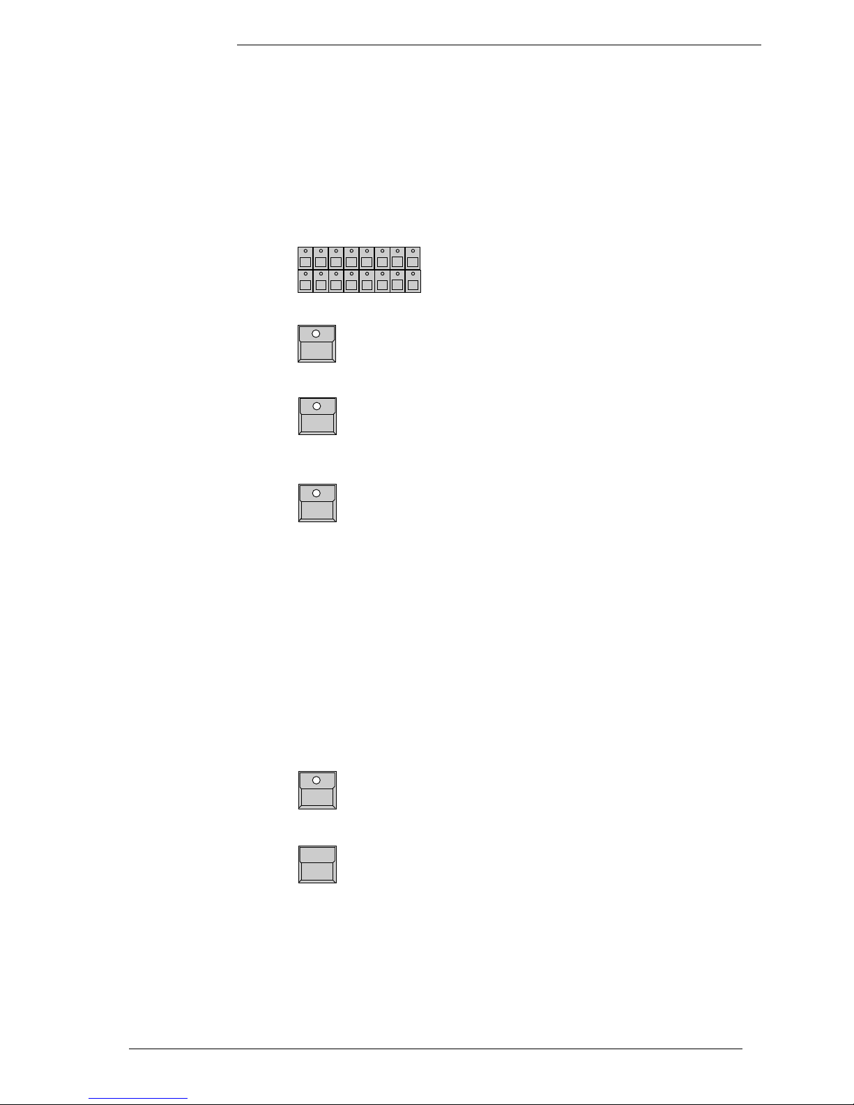
The squares in the display show the current function of your 12 buttons around
the display. The 3 encoders are dedicated to the 3 lower squares of the
display.
By pressing the Quit button 2 x you can return to the TOP MENU. The current
operation will be cancelled and the board returns to the normal operation
mode.
The encoder wheel no.2 can be used to modify the speed of all active fades
(see 9.1 for details).
Display buttons
Quit button
Running fade
modification
V. 4.11
MA Lighting Technology GmbH . Dachdeckerstr. 16 . D-97297 Waldbüttelbrunn . Fax: + 49 9 31 4 97 94 29 . www.malighting.de
88
88
8
In the "Scan Selection" block the buttons have to be
switched on according the number of scans to be
registered.
Manufacturer Name
When pushing the desired button, the square of that
manufacturer will be shown inverted.
Encoder 1:
In the lower section of the display you find the first
types of fixtures of the selected manufacturer. Turning Encoder 1 will scroll through the list of available
lamps. If there are "Presets" for the chosen type the
scan type will be shown inversely.
READY
After selecting the desired lamp type, press READY
INIT:SCANS+VALUES+NAMES
All necessary data for this scan type is now
downloaded. The three other kinds of initialization are
for registration of different scan types for simultaneous operation.
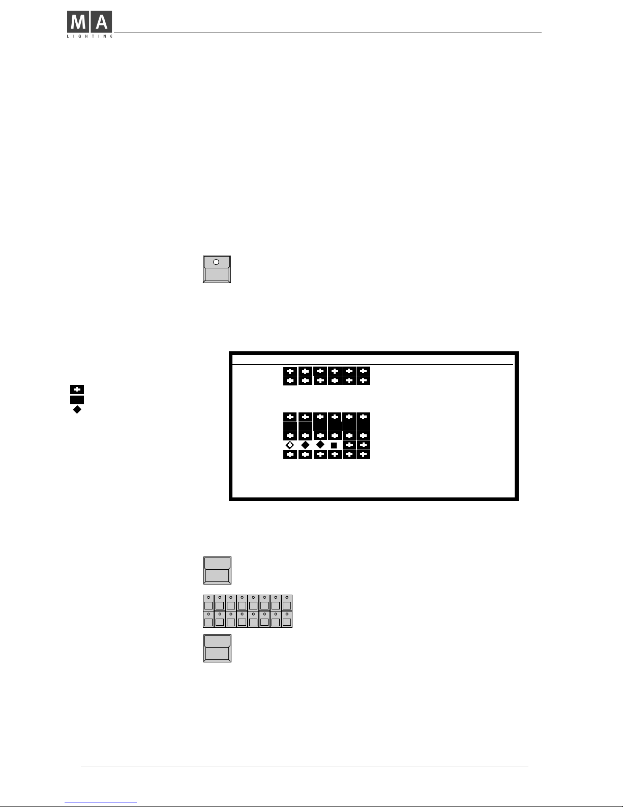
The display shows in 10
sections names of manufactures. MORE turns the
page for more manufactures. The list in the
centre shows the 16
selected lamp types.
For self-defined scans
please choose "User
Scan" (see chap. 11). You
can call 16 different scans
which were defined by
yourself previously.
Selecting number of Scans
Selecting manufacturer and
lamp type
Registration of selected
lamp type
2.2 Lamp type
The MA SCANCOMMANDER is able to control various lamp types. All necessary
adjustments are made by simply choosing a lamp type from the list.
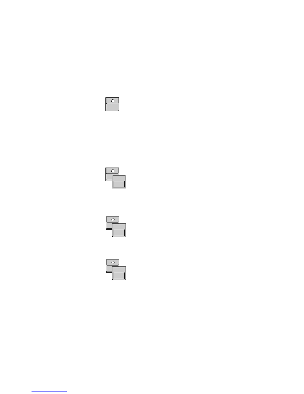
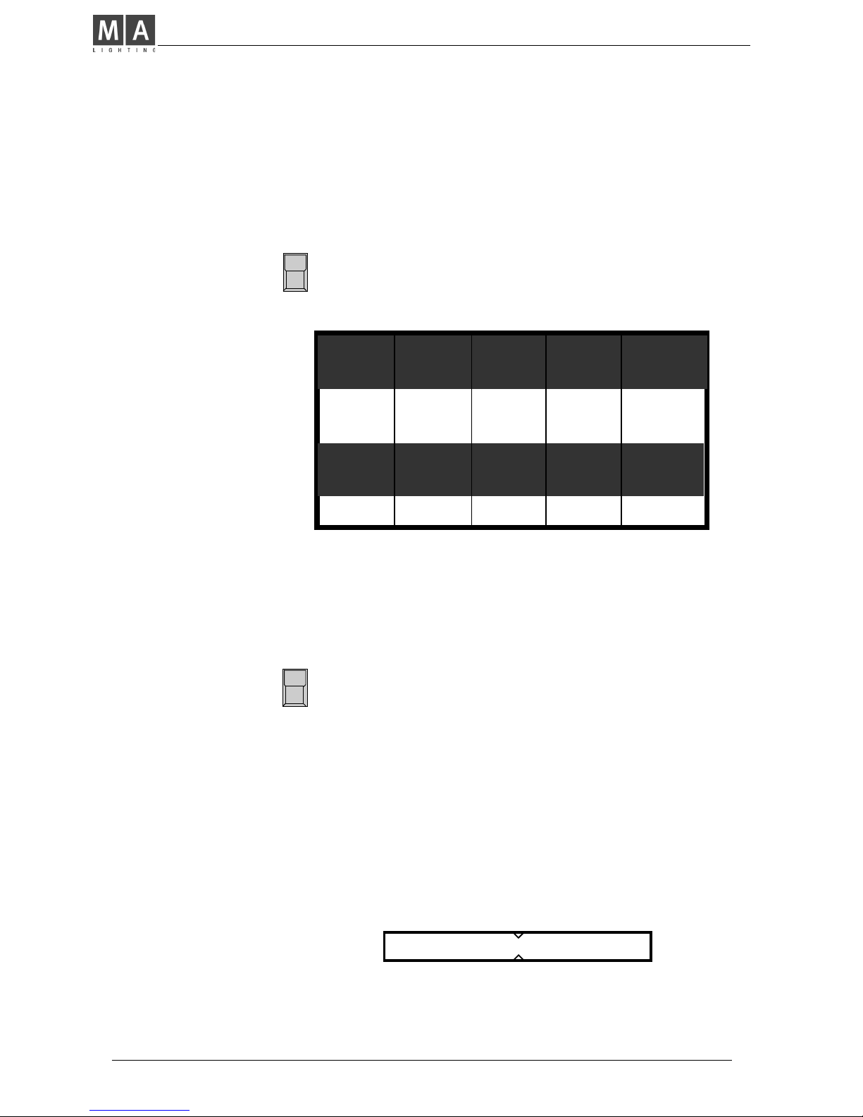
SETUP
The button on top of the display label "SETUP"
switches the board to the setup menu.
LAMPTYPE
Selecting the
Lamp Type Menu
CLAY PAKY
ITALY
CAMELEON
FRANCE
B + K
GERMANY
AMPTOWN
GERMANY
COEMAR
ITALY
FAL
ITALY
FLY
ITALY
JB
GERMANY
SELECT TYPE
MORE
READY
1(3)
1 GOLD 2
2 GOLD 2
3 GOLD 2
4 GOLD 2
5 GOLD 2
6 GOLD 2
7 GOLD 2
8 GOLD 2
LAMPTYPE SETUP
9 GOLD 2
10 GOLD 2
11 TIGER
12 TIGER
13 INTEL7
14 INTEL7
15 INTEL7
16 INTEL7
USER SCAN
GOLDEN SCAN 2 3 ( 12 )
!
LAMPO
ITALY

ScancommanderScancommander
ScancommanderScancommander
Scancommander
eMail: info@malighting.de . Tel.: + 49 9 31 4979 40 . User's Manual Scancommander
99
99
9
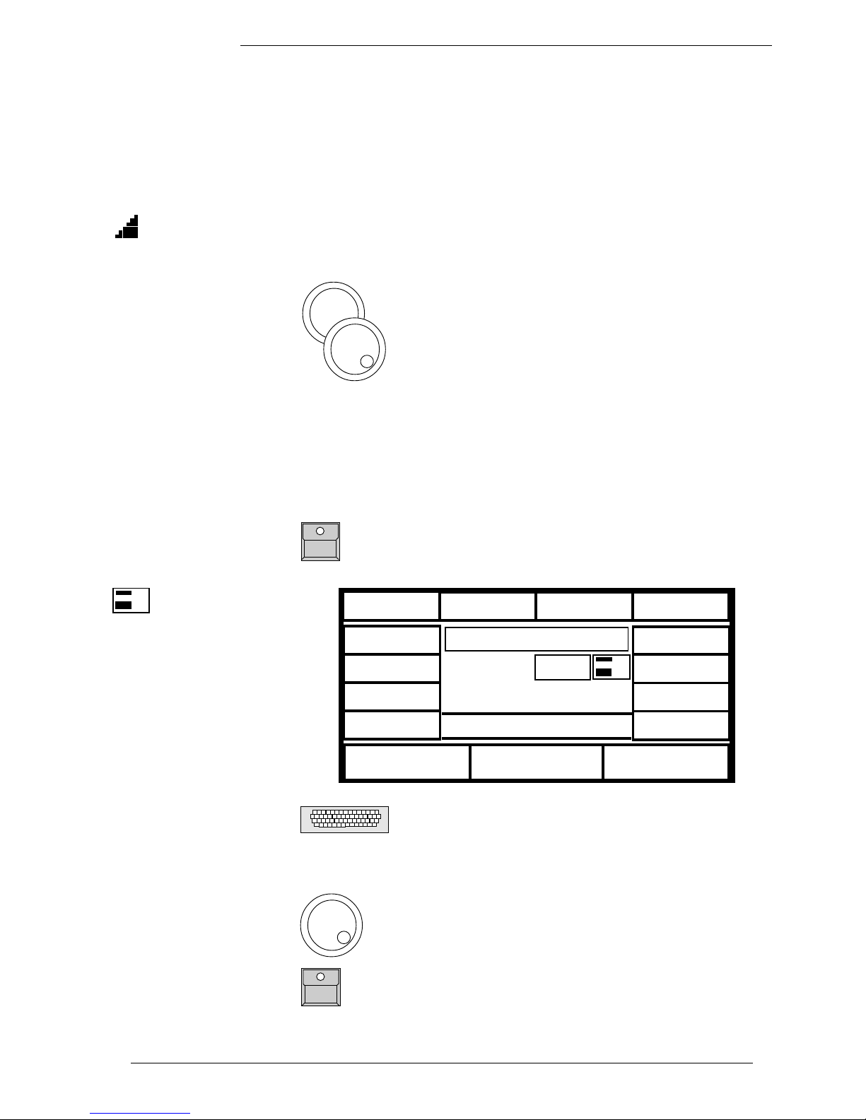
The DMX Output Patch
Menu shows three lists of
16 DMX addresses each.
The first list concerns the
scans, list 2 and 3 are for
additional dimmers and
color changers
(>>Extra1,Extra2) .
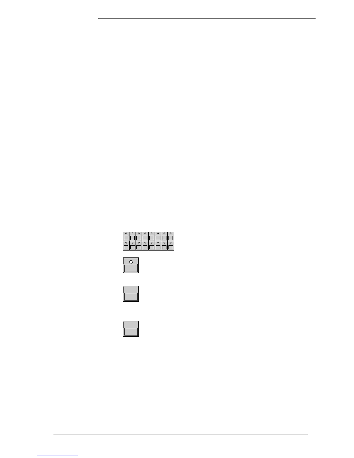
SCANS
The square SCANS has to be inverted.
SCAN Selection buttons
DMX start addresses have to be set one by one for all
scans. The scans have to be selected by their respective button in the SCAN SELECTION block.
Encoder 1:
Selects the startaddress. An address is only possible to select, if the number of channels, needed for
this scan, is freely available (Number in brackets
shows the number of channels, necessary for the
registered lamptype)
PATCH
Registers the selected address for the activated Scan.
To go on the next automatically selected scan has to
be chosen.
Clear
Clears the registered address and enables the selec-
tion of a new start address.
Adjusting DMX start
addresses
( )
2.3 DMX output addresses
All control signals from the Scancommander are on DMX 512 and are sent on
a two conductor cable to stage. Therefore the single scans need to have a
DMX start address to know, to which data they must respond.. Usually this
address can be selected by a DIL switch directly on the lamp or at their DMX
interface.
On the SCANCOMMANDER these addresses have to be set for the individual
scans.
SETUP
DMX
EXTRA 1
EXTRA 2
CLEAR
PATCH
131
1 1 (6)
2 7 (6)
3 13 (6)
4 19 (6)
5
25 (6)
6 31 (6)
7 37 (6)
8 43 (6)
9 49 (6)
10 55 (6)
11 61 (6)
12 67 (6)
13 73 (6)
14 79 (6)
15 85 (6)
16 91 (6)
1 - - (3)
2 - - (3)
3 - - (3)
4 - - (3)
5
- - (3)
6 - - (3)
7 - - (3)
8 - - (3)
9 - - (3)
10 - - (3)
11 - - (3)
12 - - (3)
13 - - (3)
14 - - (3)
15 - - (3)
16 - - (3)
1 - - (3)
2 - - (3)
3 - - (3)
4 - - (3)
5
- - (3)
6 - - (3)
7 - - (3)
8 - - (3)
9 - - (3)
10 - - (3)
11 - - (3)
12 - - (3)
13 - - (3)
14 - - (3)
15 - - (3)
16 - - (3)
Scans
Dimmer
MA Lighting Technology GmbH . Dachdeckerstr. 16 . D-97297 Waldbüttelbrunn . Fax: + 49 9 31 4 97 94 29 . www.malighting.de
1010
1010
10
2.4 Movement direction on DMX mode
The movement of the beams can be controlled via two of the encoder wheels,
an external tracker ball or computer mouse. To reach an ergonomic handling of
the trackerball it is possible to do a course adjustment of the movement.
SETUP
DMX MOVEMENT
PAN
T I
LT
INVERT
TILT
INVERT
PAN
CHANGE
PAN<>TILT
CENTER
4
PAN: 128 , TILT : 266
SCAN Selection
Selection of one single scan.
CHANGE PAN<>TILT
Exchanges the DMX signal of the pan and the tilt
channel.
INVERT PAN or INVERT TILT
Changes the direction of the pan or tilt channel.
Using the DMX mode, the values, adjusted on the Scancommanders display,
are send directly as DMX values to the lamps.
Beside this mode the Scancommander offers a stage adapted way of controlling pan and tilt. The difference between this two modes are listed in the
following chapter and in 3.3.1.
ScancommanderScancommander
ScancommanderScancommander
Scancommander
eMail: info@malighting.de . Tel.: + 49 9 31 4979 40 . User's Manual Scancommander
1111
1111
11
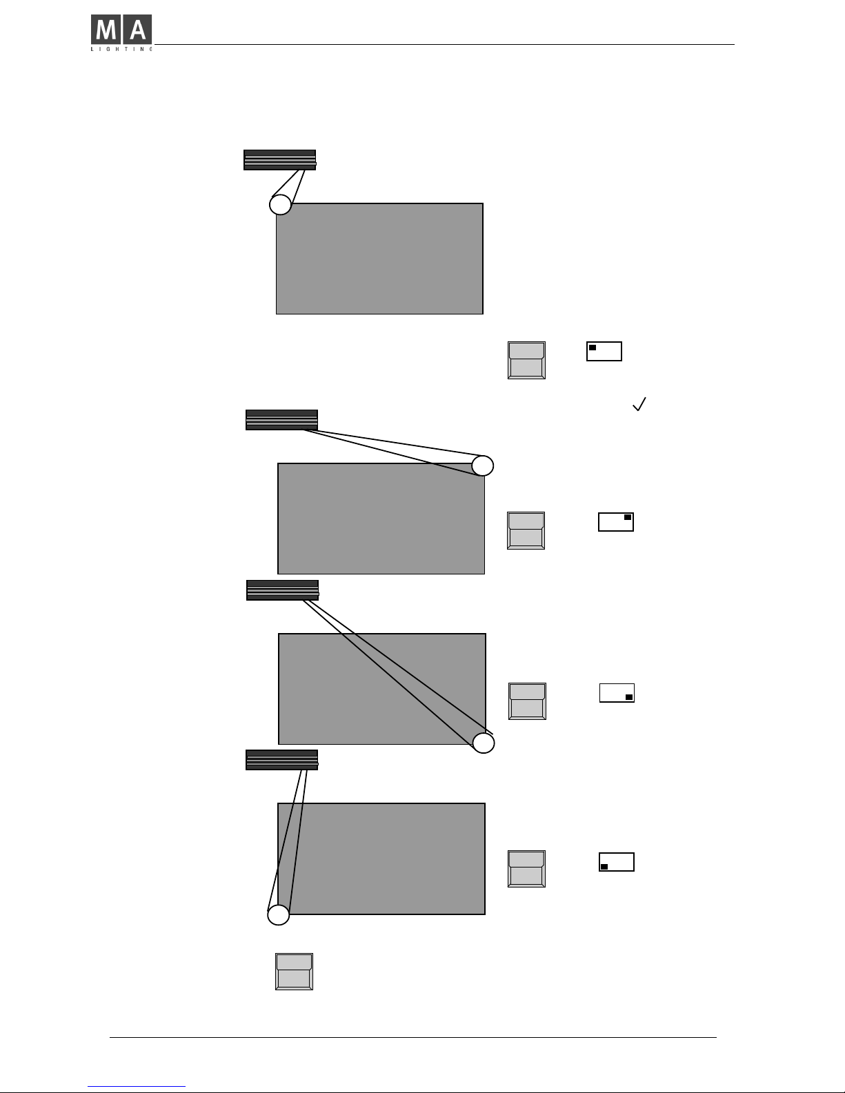
2.5 Initializing of stage
Optionally movement and positions of the light beam are handled as X/Y
coordinates on stage. The value 0/0 corresponds to the middle of the stage.
Changing the X value relates to movement right or left, changing Y moves
between front and backside of the stage. This way of calculation makes it
necessary to do an initialization before starting the programming of scenes,
but gives you a list of advantages
- Programs can be easily transferred to a new stage setup.
- On followspot mode via trackball all beams stay together.
- Moving the trackball or mouse in one direction will move the beam of all
lamps the same direction.
To be able to use these advantages, the stage has to be "shown" to the single
scans. This initialization is done by pointing with the beam to the 4 corners of
the stage. (The most exact way to do this initialization is by using nearly
closed iris or small dot gobo >> see chapter 3 Direct access.)
Basic features of movement control
SETUP
STAGE MOVEMENT
The Display shows the MOVEMENT SETUP Menu.
SCAN SELECTION block
Selection of one scan.
RESET
Clears all former initializations and gives the scan a
standard movement. This is helpful if the movement
of the scan in some way is restricted by a former
initialization.
STORE
PAN
T I
LT
INVERT
TILT
INVERT
PAN
CHANGE
PAN<>TILT
Center
RESET
SET
SET
SET
SET
4
Note:
RESET data can be used
for controlling the movement, but cannot be
adapted to new stage
setups
After RESET (square inverted) the buttons CHANGE PAN<>TILT, INVERT
PAN and INVERT TILT offer the chance of a course adaptation of the
trackerball movement to the beam movement.
Changing movement
directions after RESET
PAN: -254 , TILT : 312
MA Lighting Technology GmbH . Dachdeckerstr. 16 . D-97297 Waldbüttelbrunn . Fax: + 49 9 31 4 97 94 29 . www.malighting.de
1212
1212
12
Heading the first corner on the left
backside of stage with the beam (To be
sure to get the same corner points for
all the scans, the corners should be
marked on stage with white tape
crosses.)
! Attention !
button in the DISPLAY
Initializes the new movement. Changing to
the next scan without STORE will clear the
register of the corner positions.
! STORE !
As soon as the beam meets the corner
point,
SET
- button
stores the position in a temporary data
register. The mark " " shows, that
this corner was already adjusted.
Heading the second corner
SET
- button
SET
- button
Heading the third corner
SET
- button
Heading the fourth corner
ScancommanderScancommander
ScancommanderScancommander
Scancommander
eMail: info@malighting.de . Tel.: + 49 9 31 4979 40 . User's Manual Scancommander
1313
1313
13
3. Direct access
There is constant direct access to the single functions of the scans. Any
function can be controlled for a number of scans simultaneously. The LED´s in
the Scan Selection block determine, which of the 16 scans will be affected.
The "CLEAR" button beside the "SCAN SELECTION" block clears the selection,
the "INVERT" button inverts the actual selection.
"CLEAR"-"INVERT" selects all 16 Scans.
As long as the OPTION button is held down, the lower display button on the
left side changes between the SINGLE and MULTI mode.
SINGLE: Only one scan can be selected at once. All other scans will be
deselected automatically.
MULTI: It is possible to select more than one scan at a time to be
controlled simultaneously.
3.1 Scan groups and brightness fader
Combinations of scans, which are mostly used, can be stored and recalled as
groups. In the same time, the brightness master underneath the group buttons
are masterfaders for the brightness of this combination of scans.
SCAN Selection
Selection of the scans, which shall be stored as one
of the groups.
STORE
Keep button pressed, select "SCAN" to be displayed
on white background,
...and simultaneously press...
Group button A-H
Stores the actual scan selection as group.
If you accidentally release the STORE button before pressing a group button,
press two times QUIT to return to the TOP MENU.
Group buttons, when pushed during standard running mode, always overwrite
the actual scan selection.
To have one or more of the scans lighting the stage, at least one of the group
brightness faders has to be up. Even during movement initialization there will
be no beam on stage as long as all group brightness masters are at zero.
The function "MASTERS ALL 100%" at the SETUP menu will set all master
faders to full on. This makes sense during playback of synchronised shows
but should be switched off during standard operation (white background).
Actual Scan Selection
Programming of scan
groups
! Attention !
! Attention !
MA Lighting Technology GmbH . Dachdeckerstr. 16 . D-97297 Waldbüttelbrunn . Fax: + 49 9 31 4 97 94 29 . www.malighting.de
1414
1414
14
Controlling functions via
encoder
For any selected function
the DIRECT ACCESS
Menu shows the actual
data in a list at the centre
of the display.
(Right the COLOR display)
SCAN SELECTION
The encoder always controls the scans, which are
actually selected in the selection block. Their numbers in the display list are printed inverted and the
values are modified when the encoder is used.
Encoder 1, 2 and 3
The three lower sections in the display show the
functions, which are controlled by the encoder. The
inside part of the encoder controls the function step
by step, the outside ring offers a fast and course
adjustment. (16 steps per increment).
NOTE:
As it is now possible, to select small beams and to control movement scan by scan, the stage initialization
should be done before going on with programming. This is important to have the chance of transforming
programs to new stage setups. (>>Movement initialization)
1 WHITE
2 WHITE
3 YELLOW
4 YELLOW
5 WHITE
6 WHITE
7 89 -8 89 --
FEATURE C O L O R
9 WHITE
10 WHITE
11 RED
12 RED
13 WHITE
14 WHITE
15 WHITE
16 WHITE
VIOLET
WHEEL 1
WHEEL 2
WHITE
RED
YELLOW
GREEN
ORANGE
PINK
BLUE
MORE
1(2)
3.2 Basic scan functions
3.2.1 Tuning with the encoder
All functions of a registered lamp can be selected and controlled directly. To
see any effect on stage, every lamp has to be part of at least one of the groups
and its brightness master has to be up.
FEATURE button
Selection of any function is by their button in the
FEATURE block. As soon as the EXTRA LED lites,
the red printed functions are valid.
ScancommanderScancommander
ScancommanderScancommander
Scancommander
eMail: info@malighting.de . Tel.: + 49 9 31 4979 40 . User's Manual Scancommander
1515
1515
15
3.2.2 Programming of presets
Using the Encoder Wheels, all functions are controlled in 256 steps. But for
most of the functions there are special values, which are used all the time, like
the single colours on the color channel. These values can be stored together
with a label as PRESETS and can be recalled by the push of a button later on.
On direct access the 12 display sections will show these names. For most of
the scans these PRESETS are stored internally and are downloaded when
doing the lamptype setup. If these PRESETS are not available for the actual
registered lamp type, or they are not right and have to be adjusted, you have to
swop to the PRESET ADJUST menu.
QUIT button
The display switches to the TOP MENU.
PRESET
The display shows the actual output values and the
headline "Adjust Preset".
Feature button
Presets can be programmed for all functions. Also for
PAN/TILT, positions can be prepared as presets.
Display button of the desired square
Short push (<1/2 sec.) of a button inverts the square.
KEYBOARD
Input of a name with up to 6 characters.
ENTER or RETURN (KEYBOARD)
Stores the name for the preset.
Adjustment of values via SCAN SELECTION and ENCODER 1 to 3.
1. x STORE button
All Scans, where the function is available, are selected
2. x STORE button
For all selected scans the actual output values are
stored as PRESET.
Preset button pressed for more than 1/2 sec
The selected PRESET will be recalled and can be
modified and stored.
After the second STORE the next PRESET can be programmed or the desk
will return to the TOP MENU by using the QUIT button.
PRESETS
PRESET names
Adjusting values
Saving a PRESET
Testing and modifying
PRESETS
MA Lighting Technology GmbH . Dachdeckerstr. 16 . D-97297 Waldbüttelbrunn . Fax: + 49 9 31 4 97 94 29 . www.malighting.de
1616
1616
16
Playback PRESETS
3.2.3 Playback of presets
(X-Fader in the Feature block zero)
Feature Button
Selects a function for direct access.
Display buttons
In direct access mode preprogrammed PRESETS
can be recalled by their button. Similar to the control
via encoder, only the scans which are actually
selected, will change to the new value.
Display list:
If the actual value of a scan was selected by recalling a preset, the list will no
longer show the channel value, but will show the preset name.
Encoder 1 to 3
Modifications via encoder:
- Any modification via the encoder will change the
display to show the actual output value. If the value
returns to the preset value, the display returns to
show the preset name.
Slow x-fades to a preset value:
X-FADER (FEATURE SELECTION BLOCK)
The x-fader in the feature selection block sets the
time for the slow fade. On any recall of a preset, while
this fader is raised to a value above zero, the channels
will slowly change from their actual output value to
the value stored in the preset.
When recalling a preset for a switch function like
gobo, this fader should be down, otherwise the gobo
wheels will slowly change to the selected new gobo.
Preset X-Fades
ScancommanderScancommander
ScancommanderScancommander
Scancommander
eMail: info@malighting.de . Tel.: + 49 9 31 4979 40 . User's Manual Scancommander
1717
1717
17
The SAMPLE function enables the recall of up to nine presets even for different
features simultaneously. The SAMPLE preset commands can be created in
advance and are listed in the display, as soon as the SAMPLE button is
pressed.
SAMPLE - keep button pressed
As long as the sample button is pressed, the SCANCOMMANDER works in the SAMPLE mode.
- the display shows a insert window with up to nine
preset recalls.
- Preset commands will not be executed but listed in
the Display
- The GO+ button of the sequence will not recall the
next step of the sequence, but will recall the sampled
preset recalls.
SAMPLE function
SAMPLE display
SAMPLE button and simultaneously
any Preset button in direct access
The Preset are not executed, but are listed in the
SAMPLE list together with the actual scan selection
and the actual x-fade time.
SAMPLE button and simultaneously
GO + button of the sequence section
The listed preset recalls get executed. The list will
not be cleared and can be recalled again later on.
Any new preset command, which is sampled in the list, may overwrite and
therefore automatically clear a former command. (For example if a new
command sets a gobo for all scans, any former gobo commands in the sample
list are cleared.)
SAMPLE button and simultaneously
CLEAR button in the feature section
The SAMPLE list will be cleared.

MA Lighting Technology GmbH . Dachdeckerstr. 16 . D-97297 Waldbüttelbrunn . Fax: + 49 9 31 4 97 94 29 . www.malighting.de
1818
1818
18
3.3 Movements
Controlling the movement works basically like controlling any other function.
Positions, which are stored as presets, can be recalled by their buttons. The
scan selection block shows, which of the 16 scans will go to the new position.
When a preset is recalled with a x-fade time greater than zero, the beams will
change slowly and with a linear travel from their actual position to the new one.
In addition to encoder and preset playback, there are some functions which
are only available for Pan/Tilt.
(two different mode, trackball and mouse, followspot and circle movement)
PAN/TILT coordinates
PAN/TILT via encoder
and Presets
3.3.1 Movement on direct DMX or on stage calculation
As noted in 2.4 and 2.5 on the Scancommander it can be selected between
adjusting the DMX values of pan and tilt directly or adjusting the stage position
where the scans are supposed to point to. Although it is possible to swap
between this two modes any time, it is highly recommended to select one of
the modes as basic for all programs.
Advantages and disadvantages of the two
operation modes
Stage calculation mode
- synchronously control of all scans
within the stage
- linear movement of the beam even
when using moving head lamps.
- reaching the bump position of the
yoke, the head lamp turns around.
- linear movement of the beam within
the stage area
- adapting all programs by initializing
the 4 corners
- adjustment of single presets
- without any problem up to 50% outside stage
-99 - 99
to
99 99
the rhomb marks stage coordinates,
white ramp marks a fade to stage
coordinates
DMX direct mode
Setting position:
- better control in extreme positions
far outside stage
- on moving head lamps, pan turns
the yokes while tilt turns the lamp
- the bump position of the yokes is
placed at the same side every time
the picture is recalled.
Movements on fade:
- depends on mechanical construction of the lamps
Adaptation to new stage setups:
- scans have to be mounted exactly
to the same position as before or
- all presets have to be adjusted
Follow mode:
- not possible
Display on the pan/tilt menu:
00 00
to
FF FF
(optional in % or hexadecimal)
ScancommanderScancommander
ScancommanderScancommander
Scancommander
eMail: info@malighting.de . Tel.: + 49 9 31 4979 40 . User's Manual Scancommander
1919
1919
19
- During stage oriented movement mode the value in the display reaches from
-99 to +99. The centre of the stage corresponds to 0/0, the corners have values
of +/-25. Values outside +/- 25 mean, that the beam is actually outside the
stage.
- When a preset is recalled with a x-fade time greater than zero, the beams will
change slowly and with a linear travel from their actual position to the new one.
- If the movement initialization was done correctly, any combination of scans,
which shows the same values in the display, meet the same point on stage.
Outside the stage, this effect will loose its accuracy.
Programming presets for Pan/Tilt makes movement control very handy.
44 positions on stage can be preprogrammed and recalled by their button.
In addition it helps to return to a well defined point if the operation via trackball
gets confusing.
Special regulations on
stage oriented movement
! Attention !
During any programming of positions make sure, that the circle radius is set to
zero. If only the circle speed is zero, but the radius is greater zero, there is no
circle movement visible, but the radius is still valid and will cause an offset on
the programmed positions.
! Attention !
3.3.2 Changing the movement mode
SCAN SELECTION
Selection of the scans to be changed
OPTION button
keep button pressed and simultaneously press
SET SELECTION TO STAGE MOVEMENT
selected scans, which work on direct DMX mode, will
swap to the stage calculation mode and jump to "00
00" middle of stage.
SET SELECTION TO DMX MOVEMENT
selected scans swap to direct DMX mode without
changing their position.
The actual mode is marks by "S" or "D" for all 16 scans. Changing the mode
via option cancels all running fades.
The working mode is stored within any preset, memory, chaser or sequence
step. The playback of this programs automatically restores the according
working mode. Fades between two positions with different working mode
always run in DMX direct mode.
Direct setting of the
working mode
Changing the working
mode can be done by
recalling according
playbacks

MA Lighting Technology GmbH . Dachdeckerstr. 16 . D-97297 Waldbüttelbrunn . Fax: + 49 9 31 4 97 94 29 . www.malighting.de
2020
2020
20
3.3.3 Transforming memories to a new stage
Transforming stage mode data:
All movement positions which are stored as presets, memories or scenes, are
automatically adapted to a new stage setup, as soon as the movement
initialization is done. Therefore it is important to have the first movement
initialization done before any program is stored. If the programs had been
done on the basic of an exact initialization, no further adjustments are
necessary. The same initialization is necessary, if the mounting position or
height of a scan has been changed.
Preset positions can also be adjusted, if the point they have to hit on stage,
has moved. If, for example, the position of the keyboard player has moved,
only the preset "KEYB." has to be adjusted, and any memory, chaser or
sequence step, which was programmed to meet the keyboard, will recall the
right position.
Transforming direct DMX mode data:
If programs are stored on direct DMX mode the easiest way is to adjust the
lamp position as exact as possible.
Otherwise all programs, which are based on preset positions can be transformed by simply adjusting the 44 preset positions. Stage pictures, which are
not based on presets, have to be tested and adjusted one by one.
Transforming programs to
a new stage setup
Adjusting preset positions
Transforming direct DMX
memories
ScancommanderScancommander
ScancommanderScancommander
Scancommander
eMail: info@malighting.de . Tel.: + 49 9 31 4979 40 . User's Manual Scancommander
2121
2121
21
3.3.4 Trackball and Mouse
An Atari compatible mouse or trackball makes control of movement very
comfortable. In standard operation mode, no follow spot fixed (see 3.3.3), the
mouse will always control the actual selected scans simultaneously. Unlike
the control via encoder, the mouse even works when Pan/Tilt is not selected in
direct access mode.
The mouse buttons switch the working modes, the new mode will be displayed
for one second in the centre of the display.
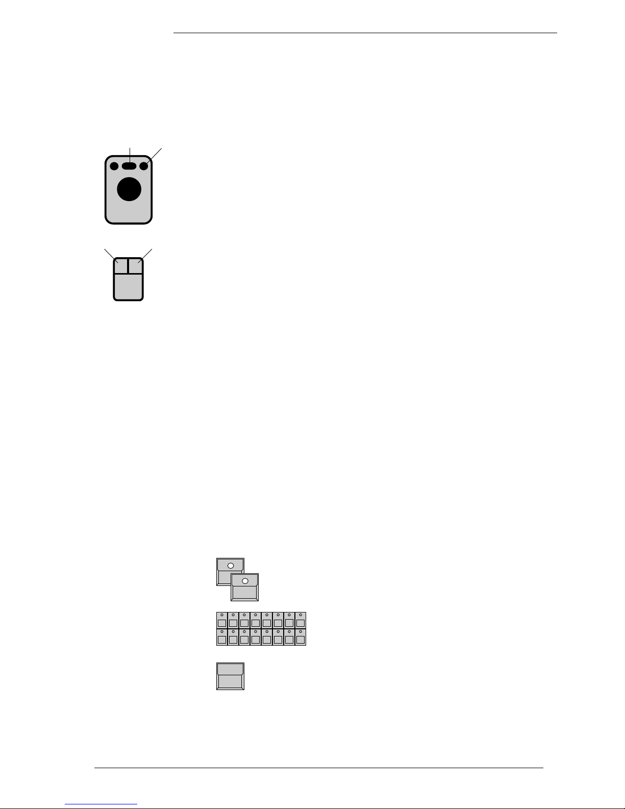
Right mouse button (outer buttons on the trackball):
Switches the mouse on and off, to avoid accidental
movements.
Left mouse button (inner button on the trackerball)
Mouse speed changes between slow and fast.
3.3.5 Followspot mode
The Pan/Tilt calculation via the stage coordinates has the effect, that all
beams, starting at the same point, stay together during simultaneous operation. Outside the stage this effect looses part of its accuracy.
To have a real tracking of a person moving on stage, it is necessary to do the
movement initialization of the four corners at about 1.5 m height, otherwise the
beams will perfectly light up the feet of the person, but not the body. Therefore
the corners have to be marked by a microphone stand or something similar.
In standard operation mode, the mouse controls the actual selected scans.
Using the EXTRA-FOLLOW feature, it is possible to fix one group of scans to
the mouse. Any change of the scan selection while controlling colours, gobos
or any other feature, will not affect the follow selection. The mouse will go on to
control their scans.
Additionally the scans, fixed to the follow mode, won't be affected by any
memory or playback program.
EXTRA LED has to be switched on
FOLLOW
The display changes to FOLLOW FIX Menu with the
list of Pan/Tilt coordinates.
SCAN Selection
Selection of scans, which shall be fixed to follow
mode.
FREEZE FOLLOW inverted
The selected scans are fixed to follow mode.
MODE PROGRAM inverted
Standard operation mode. The mouse always controls the actual selection of scans.
Followspot in standard
operation mode
On/OffSlow/Fast
Slow/Fast
On/Off
Fixing the followspot
mode
MA Lighting Technology GmbH . Dachdeckerstr. 16 . D-97297 Waldbüttelbrunn . Fax: + 49 9 31 4 97 94 29 . www.malighting.de
2222
2222
22
3.3.6 Circle mode
The feature EXTRA - CIRCLE offers direct control of circle movements. The
actual Pan/Tilt position will be the centre point of the circle movement, radius
and speed can be controlled by encoder. By moving the Pan/Tilt position, the
circle will move simultaneously.
Circle parameters can be stored as presets like any other feature and can also
be stored within memories, chasers or sequence steps.
(>>Programming selective memories).
Speed
EXTRA LED has to be switched on
CIRCLE
Direct access to the CIRCLE feature can be done
with encoder or presets like on any other feature. At
least one preset should be prepared with speed and
radius set to zero for all scans.
SCAN Selection
Encoder 1
Controls the speed. Crossing zero will change the
direction.
Encoder 2
As long as the radius is zero, a starting angle can be
set between 0 to 15 (=F). This helps to start the
different scans at different positions of the same
circle.
Encoder 3
sets the radius of the circle.
Circle movement as a
Feature
Starting angle
Radius
Any circle movement can only be terminated by turning the radius to zero or
by recalling a preset, which sets the radius to zero.
For keeping control of circle movements and to have the chance to terminate
circles as quick as possible, it is recommended to program a preset for circle
"OFF".
Using the selective way of programming memories and sequence steps, it is
important to have one of the memories S1 to S10 stored as "CIRCLE OFF"
memory. (>> 4.3 Selective memories)
When a circle movement is terminated by setting the radius to zero, the beam
returns to the centre of the circle.
Terminating a circle
movement
! Attention !
During any programming of positions make sure, that the circle radius is set to
zero. If only the circle speed is zero, but the radius is greater zero, there is no
circle movement visible, but the radius is still valid and will cause an offset on
the programmed positions.

ScancommanderScancommander
ScancommanderScancommander
Scancommander
eMail: info@malighting.de . Tel.: + 49 9 31 4979 40 . User's Manual Scancommander
2323
2323
23
3.3.7 Movement speed
Slow movements are one of the major applications of moving lights. The
MA SCANCOMMANDER controls fades by updating the position about 40
times a second. The intern resolution of the SCANCOMMANDER is 1600
steps for Pan and 1600 steps for Tilt. Using one or two channels per direction,
the Pan/Tilt informations can be sent with 8 to 16 bit accuracy. Depending on
the lamp type, the single steps of the SCANCOMMANDER will be conducted
with individual degree of accuracy.
As the DMX 512 signal features a 8 bit resolution, it offers control with 256
steps. A much improved movement control is possible, if the lamp offers a
second channel for fine adjustment, reaching a 10, 12 or 16 bit resolution.
Unfortunately today only few of the available lamps feature this second
channel for high resolution control via DMX 512.
Some of the lamps feature an intelligent logic, which enables the lamp to
make smooth movements by creating their own intermediate steps. Therefore
these lamps show a little delay on slow movement (Hysteresis). Especially
when doing the movement setup, this may cause some loose of accuracy.
Other lamps require that the speed data are sent on a separate DMX 512
channel. As this speed information has to be set by the user any time there
are changes between fast movement and slow fades or follow spot operations,
it is not very handy.
Setting this speed to maximum leaves no chance to do slow movements, as
the lamps will jump from position to position.
Appendix 1 lists the scans, which will successfully interface with the
MA SCANCOMMANDER. Unused features such as focus or zoom can be
used as a makeshift for lamps which need additional speed information.
Controlling the movement speed of these scans can be done by programming
some selective memories on S1 to S10, which only set a value on to the speed
channels.
(>>4.3 Selective memories)
Handling within the
Scancommander
Lamp types with smooth
movements by creating
intermediate steps
Lamp types with 10 to 16
BIT accuracy
Lamp types with a speed
channel
MA Lighting Technology GmbH . Dachdeckerstr. 16 . D-97297 Waldbüttelbrunn . Fax: + 49 9 31 4 97 94 29 . www.malighting.de
2424
2424
24
4. Memories
Any picture on stage can be stored as a memory and recalled by touching a
button. If the actual position is created by recalling a preset, any modification
of this preset will cause the memory to recall the modified values. Therefore it
is no longer necessary to adjust every single scene when adapting programs
to a new stage setup.
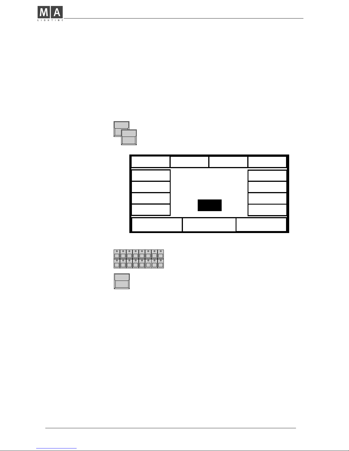
4.1 Programming of basic memories
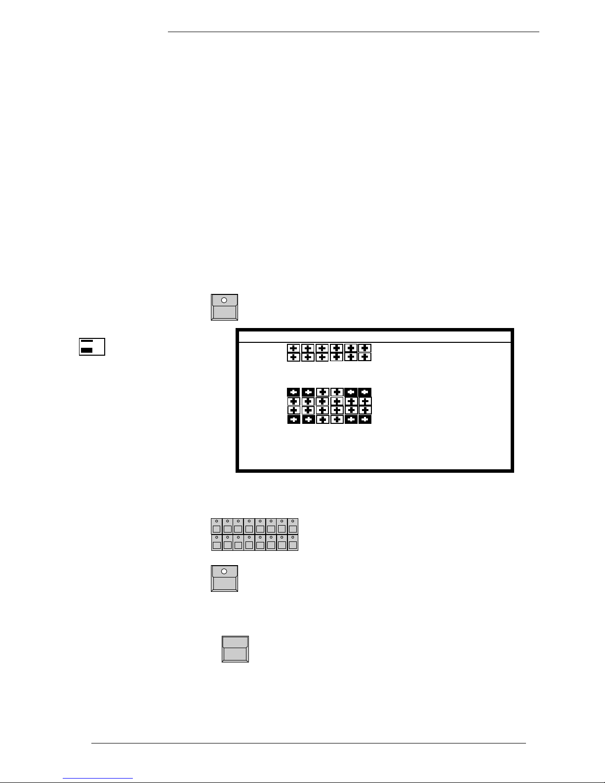
STORE button
The display shows a matrix with 16 columns for the
scans and 12 rows for the features. "-" in the matrix
indicates, that this feature is not available for the
registered scan. Small dots in the middle of a square
show, that the feature for this scan was set by the
encoder wheel, a cross indicates, that the value is a
presetvalue.
STORE MATRIX when
controlling 6 scans.
Preset values
Encoder values
Stage coordinates
For the beginning it is just
important, to have all
squares in the matrix
inverted.
(>> 4.3 SELECTIVE
MEMORIES)
Note: if the STORE
MATRIX is not completely
selected, only some of the
adjustments on stage are
stored.
(>> 4.3 Selective Memories)
During initial programming operations, all blocks within the matrix have to be
displayed in inverted contrast. In case some of the squares are not inverted,
press
1. x CLEAR button in the feature block
The matrix is cleared, all blocks are not displayed
inverted.
SCANSELECTION
Use -CLEAR - INVERT to select all scans
2. x CLEAR
The matrix is completely selected. All blocks are
displayed inverted.
The matrix is stored internally and reconstructed as soon as the next picture
is stored.
Selecting the complete
STORE MATRIX
SHUTT
IRIS
FOCUS
C-M-Y
PRISMA
COLOR
DIMMER
GOBO
MOVE
CIRCLE
SPEED
ROTAT.
EXTRA 1
EXTRA 2
SCAN No: 1 2 3 4 5 6 7 8 9 10 11 12 13 14 15 16
ScancommanderScancommander
ScancommanderScancommander
Scancommander
eMail: info@malighting.de . Tel.: + 49 9 31 4979 40 . User's Manual Scancommander
2525
2525
25
Features may be selected for slow infade (indicated by the small ramp) or for
fast switching to the new value (trig). A trigpoint will set, whether the switching
will be done at the beginning, the middle or the end of the fade.
Example: A scan may move slowly from its old position to the middle of the
stage, the color is set to change quickly at 50%, means middle of the travel.
Encoder 1
Selects a feature marked by an arrow.
Encoder 2 or 3
Switches between Trig and fade.
Ramp (black triangle): Slow x-fade
No Ramp :Switching at the Trigpoint
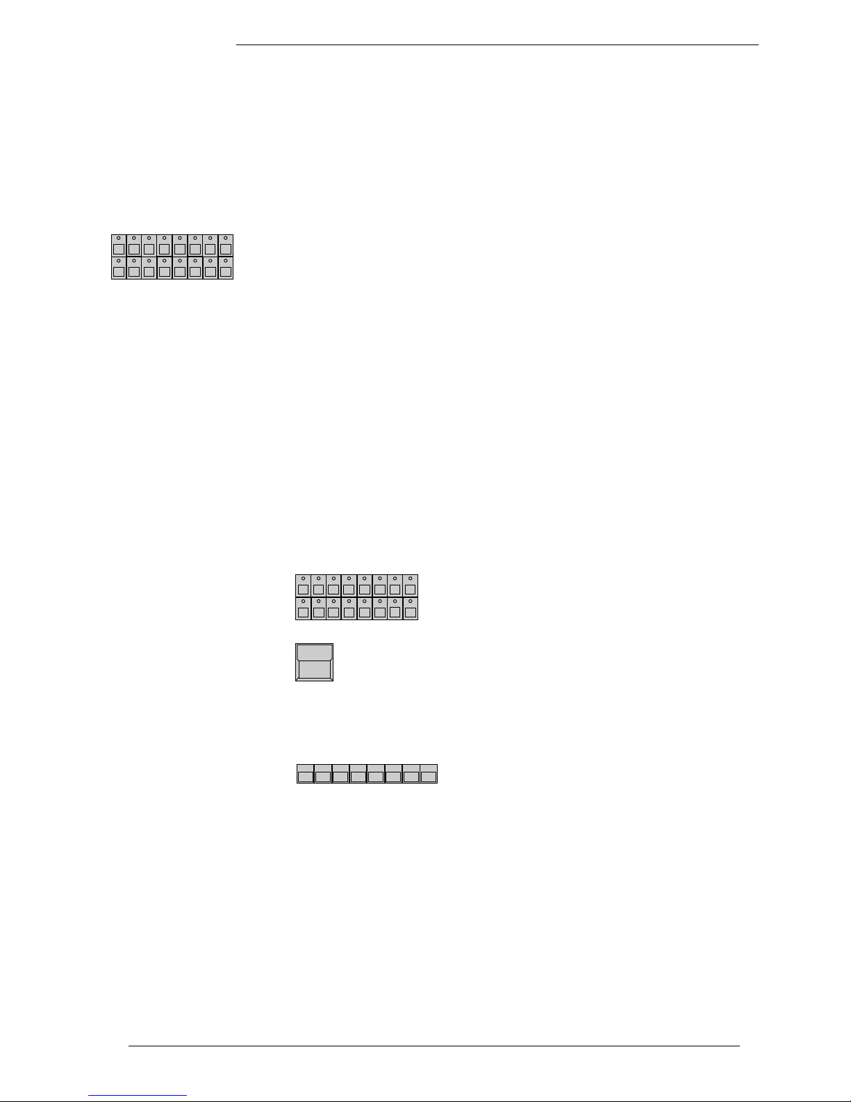
Memory pages
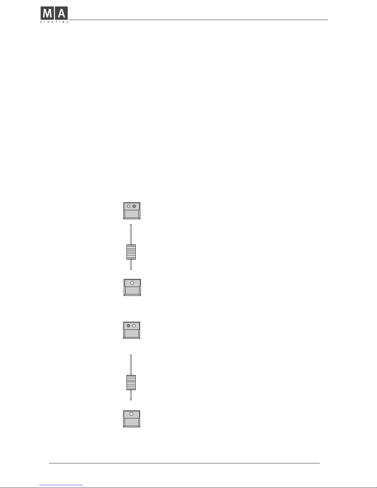
the PLAYBACK area right hand on the front panel offers 40 buttons for
memories, whereas the upper 30 buttons can be switched to 4 different pages
A to D. The right hand buttons with two LED´s are able to contain chasers. A
flashing LED in a page button shows the preselected page. The lower ten
memory buttons S1 to S10 stay untouched by the page buttons and should be
programmed to contain the mostly used memories.
MEMORY button/ (PAGE A-D)
Selects a place to store the picture as memory.
Trigpoint and x-fade
KEYBOARD
Input of a name with up to 14 characters.
ENTER or RETURN (Keyboard)
Stores the name.
Encoder 1 and 3
Sets x-fade time and trigpoint.
STORE button
Saves the actual stage as a memory.
Storing a memory
Memory name and
parameters
NO NAME
PROGRAM
MEMORY:
A 2
FADE 0.0 sec
TRIG 0 %
MEMORY
FREE: (84233)
A small graphic
shows the STORE
matrix of this memory
MA Lighting Technology GmbH . Dachdeckerstr. 16 . D-97297 Waldbüttelbrunn . Fax: + 49 9 31 4 97 94 29 . www.malighting.de
2626
2626
26
4.2 Playback memories
Memories can be recalled by their respective buttons any time. All channels,
which had been selected in the store matrix, will be set to a new value.
Therefore standard memories with completely selected store matrix will recall
one well defined picture on stage. The LED in the last recalled memory lites
up.
4.2.1 Playback with programmed x-fade time and trigpoint
For any feature which was set to x-fade mode (small ramp in the store matrix),
the output will not switch to the new value but will change slowly with the
programmed fade time.
The output of the trigger features will switch as quickly as possible to their new
value. The time of switching is set by the trigpoint.
Preprogrammed fade
time
Standard Memories
4.2.3 Playback with manual x-fade
FADE MODE switched to MAN FADE
As soon as the fader is moved to one of the end
positions (LED on), a memory can be loaded for
manual crossfade.
X-FADER
Moving the fader will crossfade the values between
the start position and the new memory.
MEMORY button during running fade
FADE LED flashes and the memory will be recalled
with its stored fade time.
Manual cross fades
4.2.2 Playback with new x-fade time
FADE MODE switched to SET TIME
X-Fader in the playback section
The x-fader will now overwrite the programmed fade
time.
Switching features will adapt their trigpoint according
the new fade time.
Overwriting the programmed fade time
Memory button
Recalls the memory with the adjusted fade time.
ScancommanderScancommander
ScancommanderScancommander
Scancommander
eMail: info@malighting.de . Tel.: + 49 9 31 4979 40 . User's Manual Scancommander
2727
2727
27
4.2.4 Freezing of single channels
The FREEZE function fixes the actual value of single channels. These channels
will no longer be affected by any playback.
SCAN Selection
Select a combination of scans
FREEZE button in the FEATURE block
keep button pressed ...(The display shows a matrix.
The already frozen channels are displayed inverted.)
and simultaneously press
FEATURE button
The LED inside the FREEZE button lights up. For the
actually selected scans the selected feature is fixed.
MEMORY button
The fixed channels get no longer affected by any
memory, even if they had been selected in the store
matrix of this memory.
Changing the scan selection and pushing another feature button will create a
combination of frozen channels shown in the display.
Selecting a feature where already some scans are fixed will clear the old
selection of scans and will freeze the new selection. This way, for single
features, the Freeze can be cleared by not selecting any scans.
FREEZE button
Direct Access via presets or encoder will work even on frozen channels. The
Freeze only protects against playback buttons like memories.
Controlling frozen channels
Changing the selection of
frozen channels
The complete freeze is cleared by pushing
FREEZE button...
and simultaneously ...
CLEAR button in the FEATURE block
The LED in the FREEZE button is dark.
All scans fixed to follow effect by EXTRA FOLLOW Mode are frozen
automatically. This is to avoid accidental changes of the beams, which are
used to track a person. (>>Fixing the followspot mode)
Automatic FREEZE on
FOLLOW MODE
Clear FREEZE
MA Lighting Technology GmbH . Dachdeckerstr. 16 . D-97297 Waldbüttelbrunn . Fax: + 49 9 31 4 97 94 29 . www.malighting.de
2828
2828
28
4.2.5 Display of Memory Names
The names of the memories, set during programming or editing, can be listed
in the display.
LIST button at the playback section
As long as the button is pressed, the display will
show the names of the actual memory page.
LIST double click (2 x pushing within 1/4 sec.)
Outside STORE, EDIT or MODIFY the list can be
recalled for permanent display by a double click. It
automatically switches off when using the display for
any other function.
All the functions of the desk remain untouched, but the display buttons and
encoders will be cancelled as long as the list is in display.
When releasing the button, the desk will return to the
last display. This list can be recalled any time, even
during STORE or EDIT function, without interrupting
the actual procedure.
List of memory names
Upper 5 buttons
Memory S1 to S10 are the
same on all 4 pages
2. line
3. line
4. line
..
..
Permanent display
The names of memory 1 to 30 are displayed with 2 x 7 characters. S1 to S10
get 7 characters each. When typing the name during STORE or EDIT, small
arrows mark the beginning of the second 7 characters.
Display buttons and
encoder locked
Setting names via key-
board
MEMORY MEMORY MEMORY MEMORY MEMORY
A/01 A/02 A/03 A/04 A/05
MEMORY MEMORY MEMORY MEMORY MEMORY
A/06 A/07 A/08 A/09 A/10
MEMORY MEMORY MEMORY MEMORY MEMORY
A/11 A/12 A/13 A/14 A/15
MEMORY MEMORY MEMORY MEMORY MEMORY
A/16 A/17 A/18 A/19 A/20
MEMORY MEMORY MEMORY MEMORY MEMORY
A/21 A/22 A/23 A/24 A/25
MEMORY MEMORY MEMORY MEMORY MEMORY
A/26 A/27 A/28 A/29 A/30
S/01 S/02 S/03 S/04 S/05
S/06 S/07 S/08 S/09 S/10
ScancommanderScancommander
ScancommanderScancommander
Scancommander
eMail: info@malighting.de . Tel.: + 49 9 31 4979 40 . User's Manual Scancommander
2929
2929
29
4.3 Selective memories
Memories and scenes may be programmed in a way, that they only affect
selected channels. When this memory is recalled by its button, all other
channels stay untouched.
Example: a memory may be supposed to recall only a new color for scan
numbers 1 to 6. The position of the beams, the gobos and all other functions
stay unchanged, when this memory is recalled. Scan no.7 to 16 stay completely untouched.
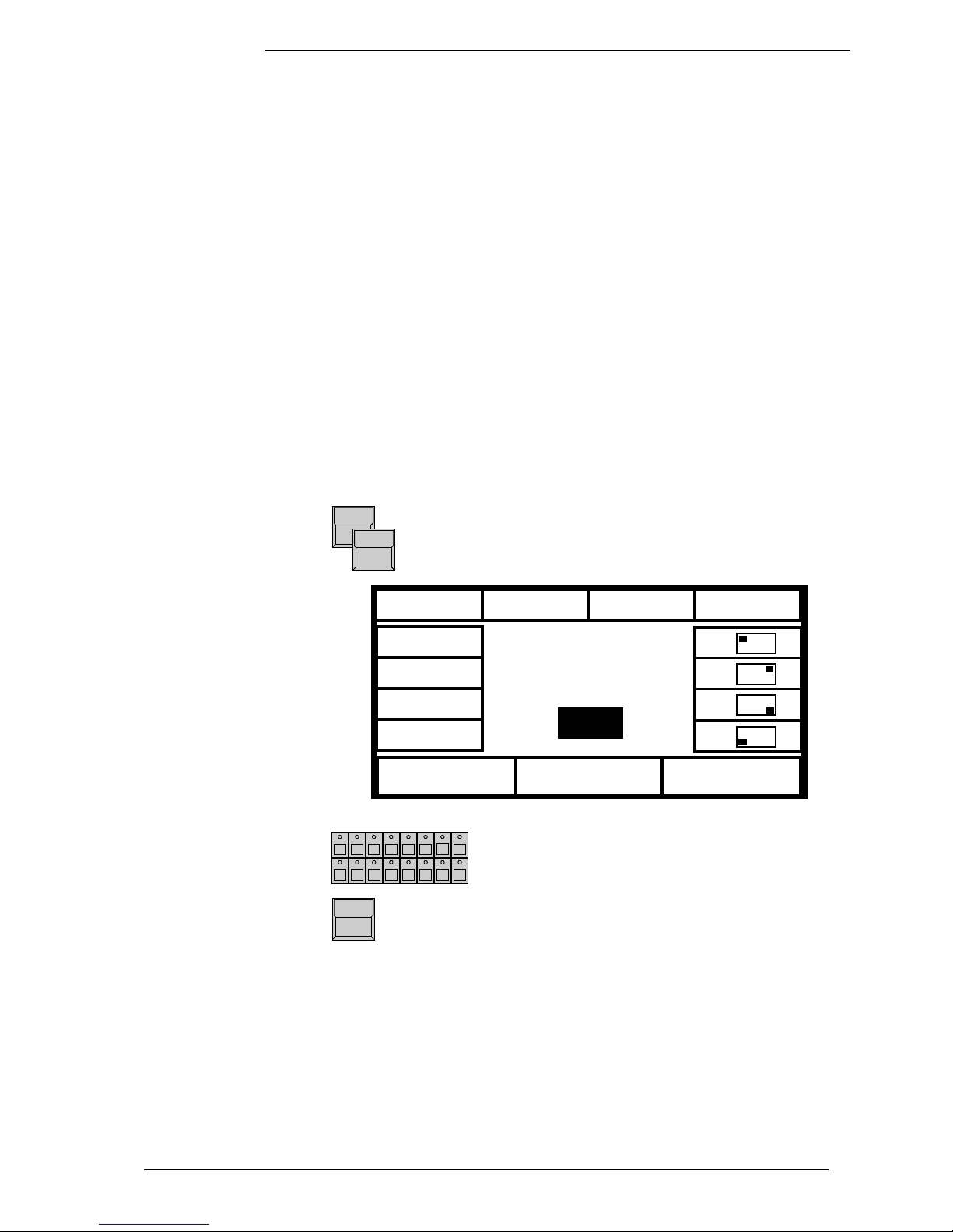
4.3.1 Programming of selective memories
The STORE MATRIX, displayed any time the STORE button is pushed to save
a picture, marks out, which of the channels will be controlled by this scene.
STORE button
Working mode of
selective memories
A small copy of
this matrix will be
displayed during the next
step and during any edit
or modify operation.
Selecting single channels
in the STORE MATRIX
Unlike programming standard memories, on programming selective memories
only a part of the channels are selected.
SCAN Selection
Selects the scans which will be affected by the
following feature
.
FEATURE button
For the actual selection of scans, this feature is
selected. Selected channels are displayed inverted.
Changing the scan selection before pushing the next
feature button enables you to select any free
combination of channels.
CLEAR button in the FEATURE block
Clears the complete matrix. The second CLEAR will
select all features for the selected scans. The third
CLEAR selects all features for all scans.
The further procedure of storing selective memories is the same as storing
standard memories.
The modified STORE MATRIX is saved internally and reconstructed as soon as
the next STORE operation starts.
( )
SHUTT
IRIS
FOCUS
R-G-B
PRISMA
COLOR
DIMMER
GOBO
MOVE
CIRCLE
SPEED
ROTAT.
EXTRA 1
EXTRA 2
SCAN No: 1 2 3 4 5 6 7 8 9 10 11 12 13 14 15 16

MA Lighting Technology GmbH . Dachdeckerstr. 16 . D-97297 Waldbüttelbrunn . Fax: + 49 9 31 4 97 94 29 . www.malighting.de
3030
3030
30
4.3.2 Playback of selective memories
Recalling selective memories works the same way as recalling standard
memories, but there are some advantages on programming selectively
Free combination of a number of selective memories:
A memory, setting the position of the scans can join
together with pure color memories or pure gobo
memories. The same color memory may be recalled
during a running chase for movement. Operating in
this way saves time when programming up and saves
storage capacity.
Saving storage capacity:
On a selective memory, only the data of the selected
channels get saved. Using selective memories
enlarges the number of chaser steps possible to
program later on.
Drawback of selective programming:
Using selective programs requires a good overview of
the stored programs. As selective memories affect
only selected channels, the picture they produce on
stage may be different depending on the picture
before.
Example: If the beams are doing a circle and a new
memory only contains a new pan/tilt position, pushing this memory will only move the centre of the
circle to the new position but will not stop the circle
movement. To stop the circle and to send the scans
to a new and well defined position, the new memory
needs to contain the information "Set radius to 00"
and CIRCLE has to be selected in its STORE MATRIX
for all the scans.
To avoid confusion on using selective memories, the
memories S1 to S10 should be programmed to contain
some standard memories with fully selected STORE
MATRIX.
In addition there should be some "Stop" memories
like "Circle Off", which only set the circle radius to 0
for all the scans, or "Shutter Strobe Off".
 Loading...