

Malibu Networks AM581 Installation Manual

TM
AirMAX
580/5800
Installation &
Configuration
Guide
November 20, 2002 P/N 8000505-000 B

ii
Malibu Networks AirMAX™ 580/5800 CPE/BTS
Trademarks
AirMAXTM and Malibu Networks are trademarks of Malibu
Networks Inc. Windows and Microsoft are registered
trademarks of Microsoft Corporation. All other trademarks are
the property of their respective holders.
Notice
All rights reserved. All information in this manual is subject to
change without notice. No part of the document may be
reproduced or transmitted in any form, or by any means,
electronic or mechanical, including photocopying or
recording, without the express written permission of Malibu
Networks Inc.
FCC Emission Information
This equipment has been tested and found to comply with the
limits for a Class B digital device, pursuant to Part 15 of the
FCC Rules. These limits are designed to provide reasonable
protection against harmful interference when the equipment
is operated in a residential installation. This equipment
generates, uses and can radiate radio frequency energy and,
if not installed and used in accordance with the instructions,
may cause harmful interference to radio communications.
However, there is no guarantee that interference will not
occur in a particular installation. If this equipment does cause
harmful interference to radio or television reception, which
can be determined by turning the equipment off and on, the
user is encouraged to try to correct the interference by one or
more of the following measures:
•
Reorient or relocate the receiving antenna.
•
Increase the separation between the equipment and
receiver.
•
Connect the equipment to an outlet on a circuit different
from that to which the receiver is connected.
•
Consult the dealer or an experienced radio/TV technician
for help.

FCC Radiation Hazard Warning
To ensure compliance with FCC RF exposure
requirements, this device must be professionally installed
outdoors on a permanent structure with an antenna that is
separated from all persons by a minimum of two meters.
Using higher gain antennas and types of antennas not
covered under the FCC certification of this product is not
allowed. Installers of the radio and end users of the system
must adhere to instructions provided in this manual.
Safety
WARNING
Warning:
service the unit or its associated power supply. This unit is
not a user serviceable device.
To avoid shock, do not open or attempt to
iii
1
WARNING
WARNING
CAUTION
CAUTION
Warning:
progress. Possible adverse health affects can occur.
Warning:
operate your wireless network device near unshielded
blasting caps or in an explosive environment unless the
device has been modified to be especially qualified for such
use.
Caution:
energy during normal operation. Do not stand or work in its
close proximity for extended periods of time to avoid possible
harmful exposure. The long-term health effects of exposure
to radio frequency energy are not fully understood.
Caution:
grounding, ensure that it presents no threat to people or
property. Verify that the antenna mast is grounded properly
and is protected from voltage surges and static charges.
Observe all regional and national building and safety
regulations.
Do not touch antennas when transmission is in
Explosive Device Proximity Warning—do not
This instrument transmits radio frequency
When performing antenna installation and

iv
Malibu Networks AirMAX™ 580/5800 CPE/BTS
Contacting Malibu Networks For Information or Support
1107 Investment Blvd. Suite 250
El Dorado Hills, CA. 95762 USA
Telephone: +1.916.941.8777
Fax: +1.916.941.8850
Web: http://www.malibunetworks.com
Email: support@malibunetworks.com

Table of Contents
Trademarks . . . . . . . . . . . . . . . . . . . . . . . . . . . . . . . . . . . . . . . . . . . . . . . . . ii
Notice . . . . . . . . . . . . . . . . . . . . . . . . . . . . . . . . . . . . . . . . . . . . . . . . . . . . . ii
FCC Emission Information . . . . . . . . . . . . . . . . . . . . . . . . . . . . . . . . . . . . .ii
FCC Radiation Hazard Warning . . . . . . . . . . . . . . . . . . . . . . . . . . . . . . . . . iii
Safety . . . . . . . . . . . . . . . . . . . . . . . . . . . . . . . . . . . . . . . . . . . . . . . . . . . . . iii
Contacting Malibu Networks For Information or Support . . . . . . . . . . . . . .iv
v
Chapter 1: Introduction
Product Overview . . . . . . . . . . . . . . . . . . . . . . . . . . . . . . . . . . . . . . . . . . . .1
System Components . . . . . . . . . . . . . . . . . . . . . . . . . . . . . . . . . . . . . . . 2
Product Names and Numbers . . . . . . . . . . . . . . . . . . . . . . . . . . . . . . . . 5
Component Identification . . . . . . . . . . . . . . . . . . . . . . . . . . . . . . . . . . . 6
Minimum Installation Requirements . . . . . . . . . . . . . . . . . . . . . . . . . . . . . . 7
About This Manual . . . . . . . . . . . . . . . . . . . . . . . . . . . . . . . . . . . . . . . . . . .7
Manual Conventions . . . . . . . . . . . . . . . . . . . . . . . . . . . . . . . . . . . . . . . . . . 8
Chapter 2: Installation
Before Installation . . . . . . . . . . . . . . . . . . . . . . . . . . . . . . . . . . . . . . . . . . . . 9
Installation Overview . . . . . . . . . . . . . . . . . . . . . . . . . . . . . . . . . . . . . . . . . . 11
Mounting the BTS or CPE Antenna . . . . . . . . . . . . . . . . . . . . . . . . . . . . . . 12
Omnidirectional Antenna Mounting . . . . . . . . . . . . . . . . . . . . . . . . . . . .13
CPE Directional Antenna Mounting . . . . . . . . . . . . . . . . . . . . . . . . . . .16
Mount the ODU . . . . . . . . . . . . . . . . . . . . . . . . . . . . . . . . . . . . . . . . . . . . . .17
Connecting the Antenna to ODU . . . . . . . . . . . . . . . . . . . . . . . . . . . . . . . . 19
Connecting Ethernet and Power . . . . . . . . . . . . . . . . . . . . . . . . . . . . . . . . .20
Chapter 3: Configuration
Configuration Overview . . . . . . . . . . . . . . . . . . . . . . . . . . . . . . . . . . . . . . .23
Initial TCP/IP Configuration . . . . . . . . . . . . . . . . . . . . . . . . . . . . . . . . . . . .24
Configuring the BTS . . . . . . . . . . . . . . . . . . . . . . . . . . . . . . . . . . . . . . . . . .25
Launch a Web Browser on the PC . . . . . . . . . . . . . . . . . . . . . . . . . . . . 26
Status Web Page . . . . . . . . . . . . . . . . . . . . . . . . . . . . . . . . . . . . . . . . . 28
Configure Web Page . . . . . . . . . . . . . . . . . . . . . . . . . . . . . . . . . . . . . . . 33
1

vi
Malibu Networks AirMAX™ CPE/BTS
Adding CPEs From the BTS . . . . . . . . . . . . . . . . . . . . . . . . . . . . . . . . . . . 35
Configuring the CPE . . . . . . . . . . . . . . . . . . . . . . . . . . . . . . . . . . . . . . . . . 36
QoS Management From the BTS . . . . . . . . . . . . . . . . . . . . . . . . . . . . . . . 40
When You Log On . . . . . . . . . . . . . . . . . . . . . . . . . . . . . . . . . . . . . . . . 40
Click APPLY to Make Changes Active . . . . . . . . . . . . . . . . . . . . . . . . 40
Service Levels . . . . . . . . . . . . . . . . . . . . . . . . . . . . . . . . . . . . . . . . . . . 41
Subscribers . . . . . . . . . . . . . . . . . . . . . . . . . . . . . . . . . . . . . . . . . . . . . 43
Rules . . . . . . . . . . . . . . . . . . . . . . . . . . . . . . . . . . . . . . . . . . . . . . . . . . 45
Changing The Password . . . . . . . . . . . . . . . . . . . . . . . . . . . . . . . . . . . . . . 47
Testing BTS to CPE Wireless Communications . . . . . . . . . . . . . . . . . . . . 48
Test Web Page . . . . . . . . . . . . . . . . . . . . . . . . . . . . . . . . . . . . . . . . . . . . . 49
Statistics Web Page . . . . . . . . . . . . . . . . . . . . . . . . . . . . . . . . . . . . . . . . . . 50
WEP . . . . . . . . . . . . . . . . . . . . . . . . . . . . . . . . . . . . . . . . . . . . . . . . . . . . . . 51
Configuration Troubleshooting and Testing . . . . . . . . . . . . . . . . . . . . . . . . 51
Verify Connections by Pinging . . . . . . . . . . . . . . . . . . . . . . . . . . . . . . . 51
Diagnosing CPE Startup Failures . . . . . . . . . . . . . . . . . . . . . . . . . . . . 55
Appendix A: Specification Tables
. . . . . . . . . . . . . . . . . . . . . . . . . . . . . 57
Appendix B: ODU Ethernet and Power Cable
Appendix C: Glossary of Terms
. . . . . . . . . . . . . . . . . . . . . . . . . . . . . . . 63
. . . . . . . . . . . . . . . . . . . . 62

Product Overview
Chapter 1
Introduction
Malibu Networks 580/5800 AirMAXTM system provides
fixed wireless broadband access in the 5.8GHz band with
a wide array of features ideal for voice, video and data
communications.
AirMAX uniquely takes bi-directional IP traffic and offers
quality of service (QoS) features ideal for Internet Service
Providers and corporate facility implementations. The
system is composed of a BTS, CPE, a full featured
optional Service Management System (SMS) and
Malibu’s patent pending
The CPE and BTS portions of the system are all outdoor
units (ODU) ruggedized for the harshest environments
with an operating temperature range of up to 55oC.
Reliability and cost effectiveness were key design goals
for this system. By utilizing many standard off-the-shelf
components, AirMAX is mature, reliable, and takes
advantage of volume production resulting in the best
performance and value available today.
MAXimum IP
TM
QoS.
2
Malibu Networks AirMAX™ 580/5800 CPE/BTS
Chapter 1: Introduction
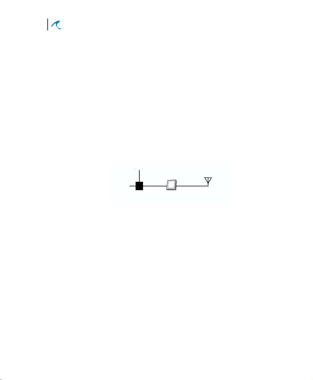
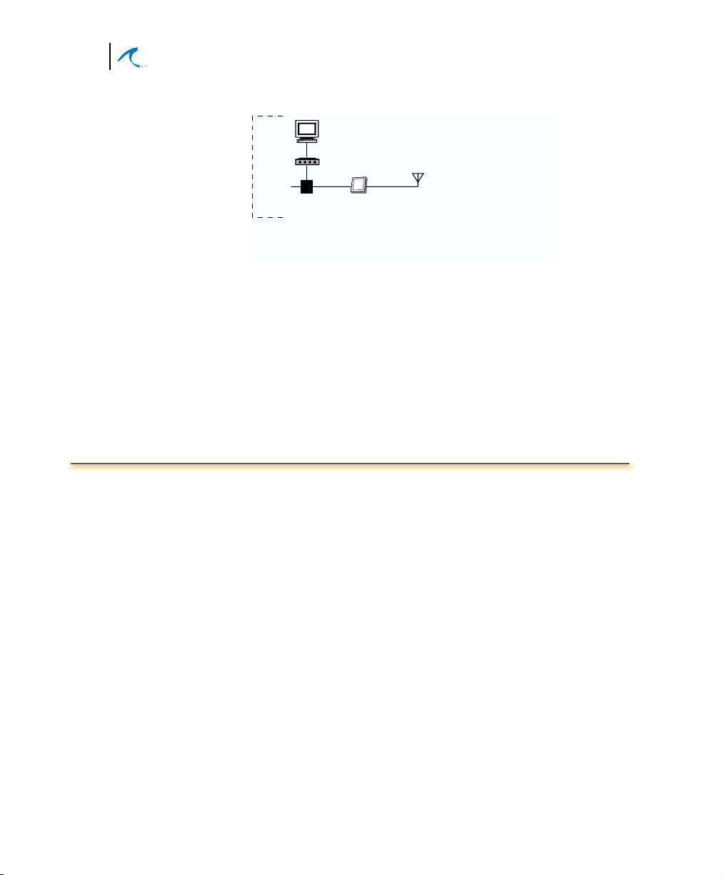
System Components
AirMAX system components are:
•
Base Transceiver Station (BTS): transmits to and
from one or more customer premises (CPE)
systems.
•
Customer Premises Equipment (CPE): transmits
from a local customer site to and from a BTS system.
Note:
Both CPE and BTS systems are functionally
similar in that they are made up of an antenna, controller
card, radio modem and power supply (items contained in
the ODU and Power Injector units). When we discuss a
BTS or CPE system therefore, remember that it consists
of an ODU and a Power Injector.
Ethernet
Power
Power
Injector
Figure 1-1. Basic System, CPE or BTS
ODU
Antenna
•
ODU: Outdoor Unit and antenna. The ODU is a
ruggedized box, often antenna-mast mounted, that
houses a radio modem and connects to an antenna.
It has a special Power-over-Ethernet (PoE) cable
that passes both data and power to/from the Power
Injector. The radio modem and circuit board inside
have non-volatile memory and a standalone CPU
that communicates with other systems. Remote
management software configures and controls the
ODU.
•
Power Injector: This unit is placed inside the
customer’s facility and connects the site’s 10/
100Base-T LAN to the ODU. It also functions as an
AC adapter that passes power to the ODU—along
with data—over the PoE ethernet cable.
Installation and Configuration
3
Product Overview
The Power Injector has two parts, an AC adapter
power module that plugs into a 100/240VAC 5060Hz source and a small module (called the power
injector) that has the two RJ-45 ethernet
connections (LAN and ODU) and connects to the
power module.
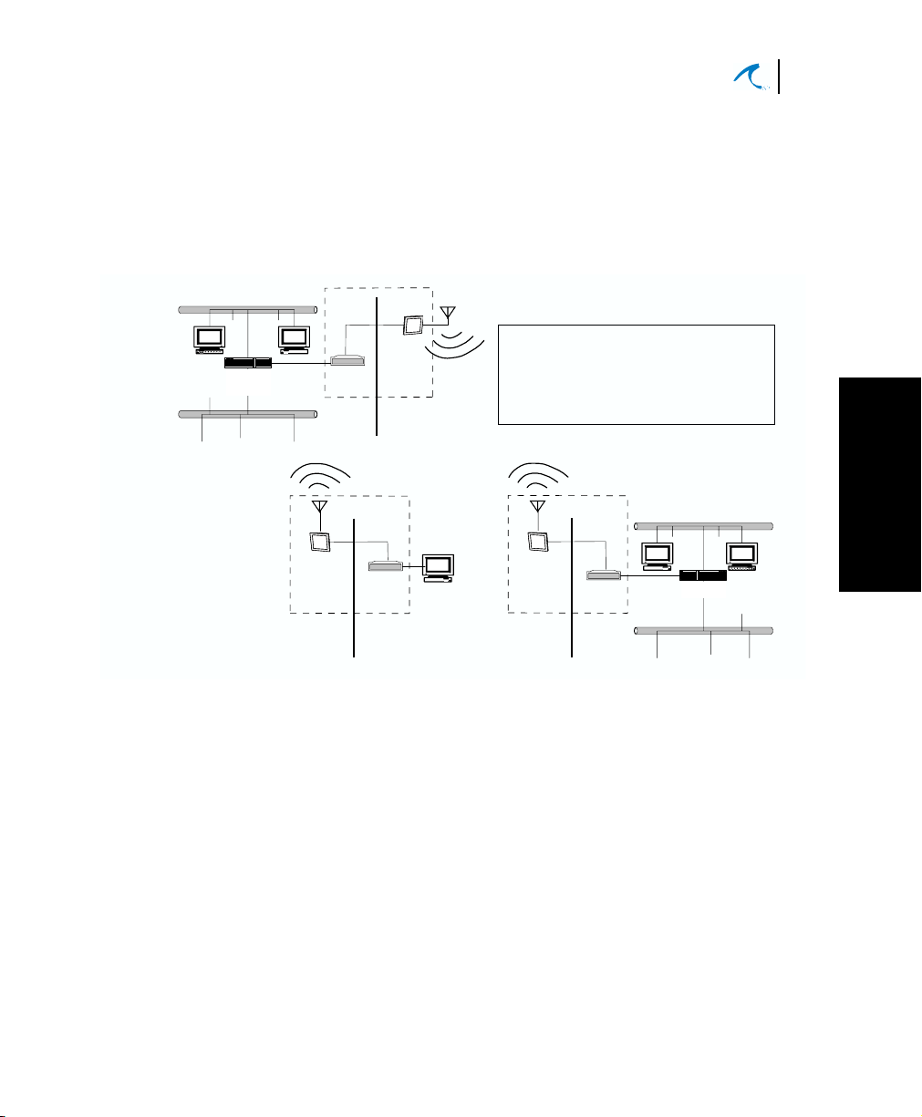
WAN
Router
PoE
Cable
ODU
To build an AirMAX system,
Power
Injector
BTS
PoE
Cable
ODU
Power
Injector
CPE
you need a BTS and one or
more CPE systems as needed
for subscribers.
PoE
Cable
ODU
Power
Injector
CPE
LAN
Figure 1-2. Simplified System Block Diagram
•
SMS: manages all aspects of AirMAX. This system
provides a robust suite of functions, from top-level
network management integration, to system
element management, to customer provisioning
and management. Features include:
Hub
1
1
Introduction
JAVA-based user interface
supports UNIX, and
Windows client platforms with one application.
Flow-through provisioning
for rapid service
configuration and deployment by any authorized
entity.

4
Malibu Networks AirMAX™ 580/5800 CPE/BTS
Chapter 1: Introduction
SNMP interface
is fully compliant with SNMP v2
using the Malibu enterprise MIB and the standard
MIB II object library.
Distributed management technology:
As the system
grows from a few base stations to as many as
hundreds of base stations, expensive, highperformance, single-point-of-failure servers can be
avoided by distributing SMS functions over a
number of low-cost servers
SLA (service level agreement) facilitation:
SMS
offers complete flexibility in service definition,
provisioning, and monitoring. In addition, tools are
provided to empower the service provider to
customize SLAs to meet unique subscriber needs,
and to meet the requirements of the operator’s
specific business model. Jitter and latency are all
configurable characteristics of each Service
Definition Suite. These definitions can be applied
on a per-flow basis.
Intelligent provisioning:
resource management is
efficiently accomplished with constant monitoring of
current service level agreements and available
system resources, preventing unwanted oversubscription of guaranteed services. In this way,
new subscribers and their services can be added to
the network with the assurance that existing service
level agreements will continue to be fully supported.

Installation and Configuration
Product Overview
•
MAXimum IP (QoS):
immediate, dramatic increase in their bottom line
due to Malibu’s QoS implementation in AirMAX.
MAXimum IP accomplishes this through two
primary means. First, the efficiency of the system is
increased resulting in a subscriber throughput
improvement compared to similar systems without
MAXimum IP. Second, MAXimum IP offers
considerably more than just minimum and
maximum bandwidth control per CPE and per
subscriber behind the CPE, a claim no other
vendor can make today. MAXimum IP also gives
the service provider the ability to control jitter and
latency as well as enabling additional high value
services to be sold and supported.
a service provider will see an
5
1
1
Introduction
Product Names and Numbers
The following list shows the available Malibu Network
Product names and numbers:
5.8 GHz Products
•
AirMAX 5800 BTS (360 degrees)
•
AirMAX 580 CPE
•
ANT-58-14-D 14 dBi Directional CPE Antenna
•
ANT-58-11-D 11 dBi Directional CPE Antenna
•
ANT-58-10-O 10 Omni BTS Antenna
•
Antenna Interconnect Cable, 4 foot, 1.5 dB loss
System Options:
• Power-over-Ethernet Cables:
PoE-25: 25 ft. (7.62m) Power-over-Ethernet cable
PoE-50: 50 ft. (15.24m) Power-over-Ethernet cable
PoE-100: 100 ft. (30.48m) Power-over-Ethernet cable
PoE-150: 150 ft. (45.72m) Power-over-Ethernet cable
PoE-200: 200 ft. (60.96m) Power-over-Ethernet cable
PoE-250: 250 ft. (76.2m) Power-over-Ethernet cable
•
SMS: Service/Element Management System
6
Malibu Networks AirMAX™ 580/5800 CPE/BTS
Chapter 1: Introduction
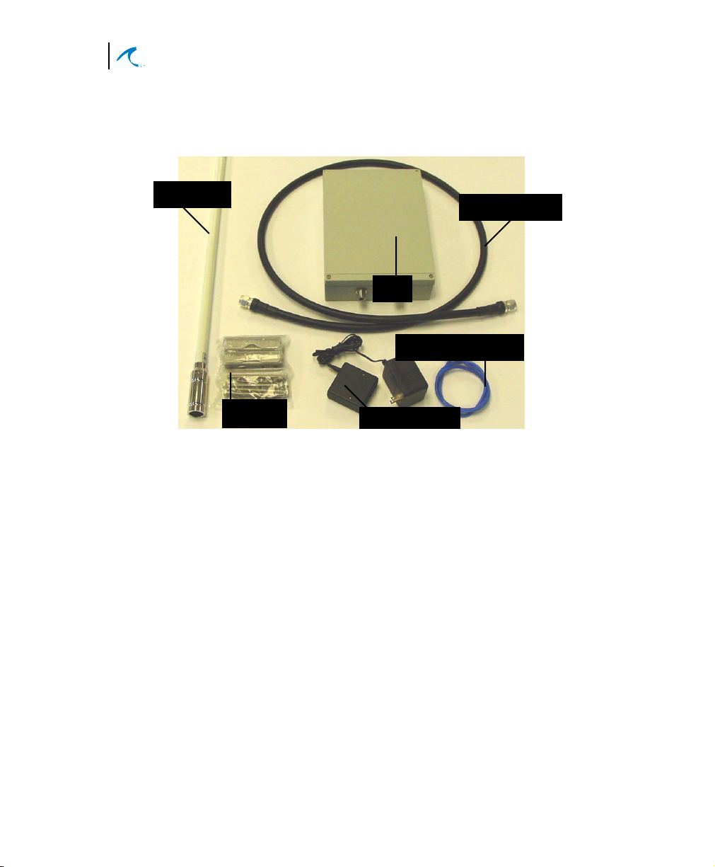
Component Identification
Antenna
The main physical components comprising the system
are shown in the following photographs.
Antenna Cable
ODU
PoE Ethernet Cable
Antenna
Bracket
Figure 1-3. Typical Components of a BTS or CPE
Note:
Omnidirectional Antenna shown—antenna
Power Injector
models differ in appearance, size, and associated bracket
hardware. Included ODU mounting brackets and clamps
are not shown (they are illustrated in the installation
Chapter).

Installation and Configuration
Minimum Installation Requirements
Minimum Installation Requirements
An AirMAX system requires the following customersupplied items when performing installation and
configuration:
•
Computer with an Internet web browser that
supports Javascript. Examples in this manual show
the Windows OS, although most operating systems
can be used. The computer or workstation must
have a 10/100Base-T Ethernet card (NIC).
7
About This Manual
• Category 5 crossover Ethernet cable with RJ-45
connector between the PC and the Power Injector.
If desired, you could also connect through a hub or
switch.
Note: When configuring a BTS and a CPE, they
should not be set up on the same LAN segment.
This manual is intended for AirMAX system installers
and as background reference information for system
administrators. For detailed software configuration and
remote management information see the AirMAX
System Administration Guide.
1
1
Introduction
8
Malibu Networks AirMAX™ 580/5800 CPE/BTS
Chapter 1: Introduction
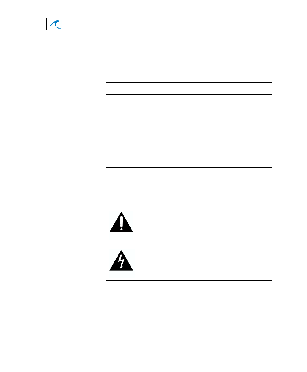
Manual Conventions
Malibu Networks publications use the following
conventions for better readability and communication of
information:
Convention Description
italics
[text in brackets] Optional items, keywords, or parameters.
boldface Keywords or commands.
{ x | y | z } When a choice exists between keywords
on-screen text Text displayed on a computer screen will
Note Advisory notes or comments will be
CAUTION
WARNING
Reference to an explicit button name when
discussing a screen (spelling and case will
match button item), or a reference to a
specific topic or heading in the manual.
or options, the options will be listed
between braces, each separated by a
vertical bar.
be shown in a monospaced font.
indicated by the word “Note” in bold
followed by the supporting text.
Important notes or comments
communicating safety issues or
possible damage to equipment will be
indicated by the Caution symbol.
Important notices about danger to the
reader, including injury or fatal
consequences, will be indicated by the
Warning symbol.

Before Installation
Chapter 2
Installation
When preparing to install an AirMAXTM system, first
ensure you’ve gathered all the information needed:
• Analyze environmental and facility requirements and
determine antenna, ODU, and Power Injector
mounting locations. Ensure locations offer optimum
direction for the terrain.
• Temperature limits at ODU mounting locations
should be within this range: -30
• Temperatures at Power Injector mounting locations
should meet normal office or home conditions.
• Decide on antenna mounting specifics: do you want
to pole or wall-mount the ODU? Locate antenna as
high as practical for best coverage.
o
C to +55oC

10
Malibu Networks AirMAX™ 580/5800 CPE/BTS
Chapter 2: Installation
• Ensure antennas between communicating AirMAX
systems are within a 12.4 mile range (20Km). You
can have up to 100 subscribers per CPE and up to
100 CPEs per sector (with 500 subscribers per
sector).
• Ensure that the overall Ethernet cabling between the
ODU, Power Injector, and customer LAN connection
(router/switch/etc.) is less than 300 feet total. If you
need a longer distance, you can insert signal
conditioning equipment between the Power Injector
and customer equipment. The PoE cables supplied
by Malibu are from 25 feet to 250 feet in length.
Caution: when making actual cable connections at the
time of installation, do not confuse the ethernet cable from
CAUTION
the customer’s LAN to the Power Injector—which is data
only and does not have power—and the PoE Ethernet
cable that runs between the ODU and Power Injector—
which does have power. These connections are made at
the Power Injector, which has two RJ45 connectors, and it
is possible to plug in the wrong cable and damage
equipment. Always check which cable you’re plugging in
when making Ethernet connections to the Power Injector.
The correct Power Injector Ethernet connections are shown
later in this Chapter. This manual illustrates the
connections as the procedures are given.
• Ensure the workers installing the ODU and antennas
are experienced installation professionals familiar
with all local building codes and safety regulations,
and who are licensed for the type of work being
performed.

Installation Overview
After choosing installation locations, you’re ready for
physical and electrical installation (explained in this
chapter). Later in Chapter 3 we explain how to
configure the system via web browser. To help give you
an overview, let’s summarize the complete installation
procedure to install an AirMAX system:
Installation and Configuration
Installation Overview
1. First, install the physical BTS system hardware,
including ODU, Power Injector, antenna, and
cabling.
2. Connect a PC to the Power Injector with a
crossover cable or LAN connection, set the IP of
the PC to a value compatible with the BTS, and
then configure BTS software from a web browser
by entering the IP address of the BTS.
3. From the same PC connected to the BTS, add
the CPEs you wish to communicate with the BTS.
4. With the BTS now installed and configured, you’ll
next install the physical CPE system hardware,
including ODU, Power Injector, antenna and
cabling.
5. Now, just as the BTS was configured, you’ll then
connect a PC to the CPE’s Power Injector, set the
IP of the PC to a value compatible with the CPE,
and then configure the CPE’s radio modem. As
on the BTS, you’ll enter the default factory IP
address of the CPE into the PC browser to
connect to it. .
6. Finally, you’ll test the wireless communication
between BTS and CPE using a PC attached to
one system (BTS or CPE).
11
Installation
2
12
Malibu Networks AirMAX™ 580/5800 CPE/BTS
Chapter 2: Installation
Computer with Web Browser
set IP to 192.168.1.2 with a subnet mask
of 255.255.255.0
Hub
Power
Configuration
applies to both
CPE & BTS
Or direct connect with an Ethernet crossover cable
Antenna
Power
Injector
ODU
(factory preset IP of 192.168.1.1
that you can change after installation)
Figure 2-1. Basic Component Overview
Now that you have an overview, let’s begin the physical
installation of CPE and BTS components—antenna, ODU
and Power Injector units, and cabling through the
remainder of this chapter (steps 1 and 4 in our previous
overview).
In Chapter 3 we’ll go through all the detailed steps of
configuration.
Mounting the BTS or CPE Antenna
The antenna supplied for use with ODUs can be omnidirectional or directional. Positioning of BTS
omnidirectional antennas is somewhat flexible. However,
care should be taken to position it where topography or
buildings do not impede transmission. CPE directional
antennas require much more care in mounting since they
must be directed toward the BTS antenna. Generally you
should always plan for a line of sight position between
antennas where possible.
Mount the antenna clear of obstructions that may affect
performance. Ensure that the antenna is mounted so that
people will be at least 2 meters away during system
operation. Pole mounting of antennas is preferable to wall
mounting. If you wall mount the antenna, you must
ensure that people on the other side of the wall will
remain 2 meters from the antenna when the system is in
operation. You may not co-locate the antenna with other
antennas.

Installation and Configuration
Mounting the BTS or CPE
To mount the antenna, follow the relevant steps for
omnidirectional or directional antennas on the following
pages.
13
Omnidirectional Antenna Mounting
1. Install a customer-supplied mast of 1 to 2 inches
(2.54 to 5.8cm) in diameter. Position the mast for
true vertical using a level. Brace the mast as
necessary so that it remains stationary in
expected wind conditions.
2. Locate the antenna mounting illustration on this
page or on the next few pages, which
corresponds to the antenna you purchased.
Follow the instructions in the illustration to mount
the antenna to the mast.
3. Slide the antenna cable up through the antenna
base or bracket(s) as directed in the illustration
and ensure all screws and mounting hardware
are tightened securely.
Installation
2

14
Malibu Networks AirMAX™ 580/5800 CPE/BTS
Chapter 2: Installation
Antenna
Antenna
Brackets
Clamp Over
Metal Sleeve
Metal Sleeve
Screw Coax
Connector
Over Threaded
Antenna Connector
Antenna Coax Cable
The other end of the cable connects
to the ODU Antenna Coax Connector
(discussed later in the manual)
Antenna Mast
Mast
Brackets
Bracket Wingnuts (8 Total, 2 each side for each bracket)
Figure 2-2. 10dBi Omnidirectional Antenna Mounting
Installation and Configuration
Mounting the BTS or CPE
15
CPE Directional Antenna Mounting
1. Install a customer-supplied mast of 1 to 2 inches
in diameter. Position the mast for true vertical
using a level. Brace the mast as necessary so
that it remains stationary in expected wind
conditions.
2. Place Antenna Brackets on back of directional
antenna and secure with the hardware supplied
(see figure).
Secure Brackets
to Antenna
using screws,
nuts, and slotted
lockwashers
(4 places)
Place Brackets
behind antenna
Secure Antenna
Assembly to Mast
using clamps (2)
and Bracket
as supplied
Installation
2
Figure 2-3. 14dBi Directional Antenna Mounting
3. Using a compass or GPS unit to judge direction,
position the antenna so it is pointed toward the
known BTS antenna location. Later in Chapter 3,
when you configure the CPE, you’ll use signal
strength and quality metrics reported by the CPE
Status web page to fine tune the antenna’s
direction.
16
Malibu Networks AirMAX™ 580/5800 CPE/BTS
Chapter 2: Installation
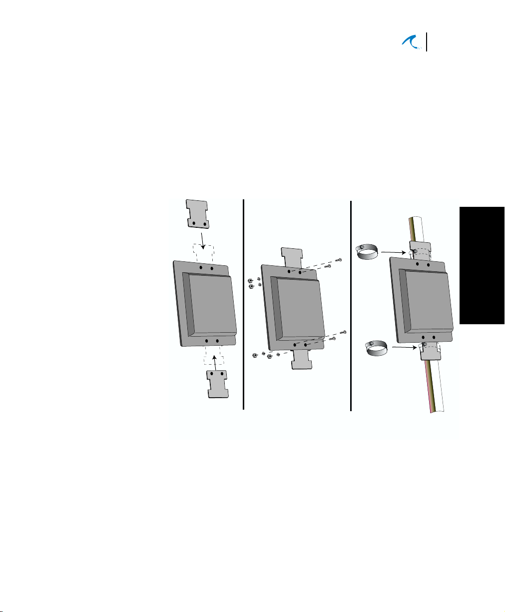
Mount the ODU
Outdoor
Unit (ODU)
Shown
Mounted
On Mast
You can mount the ODU most anywhere since it has a
ruggedized enclosure and a flexible mounting system.
If you are mounting the ODU on a mast pole, use the
included brackets to mount the unit securely.
INDOOROUTDOOR
Power Injector AC Adapter
Standard Ethernet
Cable from Customer
LAN (data only)
with RJ45 Connector
Injector
(mounted
indoor)
Power
connects to 110/220VAC
DETAIL
Power
RJ45
RJ45
Ethernet to PC or LAN
(label is marked
"To 10/100 LAN")
Ethernet to
Outdoor
(label is marked
"To AirMAX ODU")
Antenna
Cable
Power-Over-Ethernet
Cable (PoE)
Figure 2-4. ODU Mounting
Secure the two
four screws and slotted lockwashers
over 4 mounting holes (threaded)
brackets with the
provided
Place Brackets
at the four corners of the ODU
chassis back-side
Spacer (4 places)
Installation and Configuration
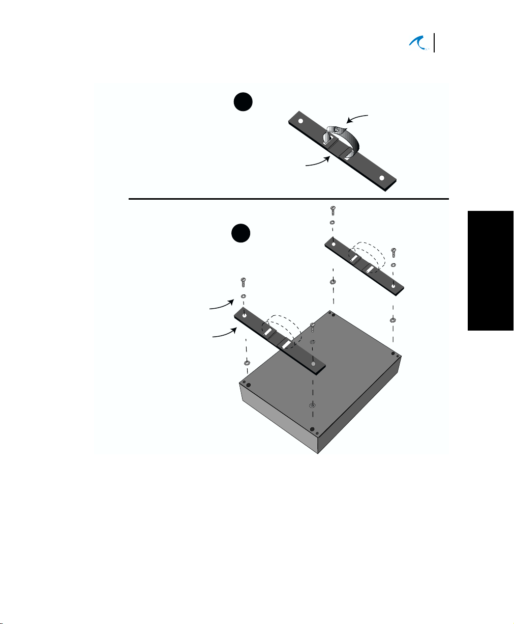
Mount the ODU
Insert circular clamp through slots in each bracket.
Tighten clamp screw to approximate size of antenna mast.
Ensure that the notched side of the bracket is toward the mast
1
side of the bracket.
Notched area
for Antenna Mast
2
Screw (4 places)
Lockwasher (4 places)
Clamp screw
17
Installation
2
Figure 2-5. ODU Mounting Brackets
The included ODU mounting brackets require that you
attach two supplied mounting brackets and circular
mounting clamps with screws. Refer to the “Attaching
ODU Mounting Brackets” illustration for instructions.
18
Malibu Networks AirMAX™ 580/5800 CPE/BTS
Chapter 2: Installation
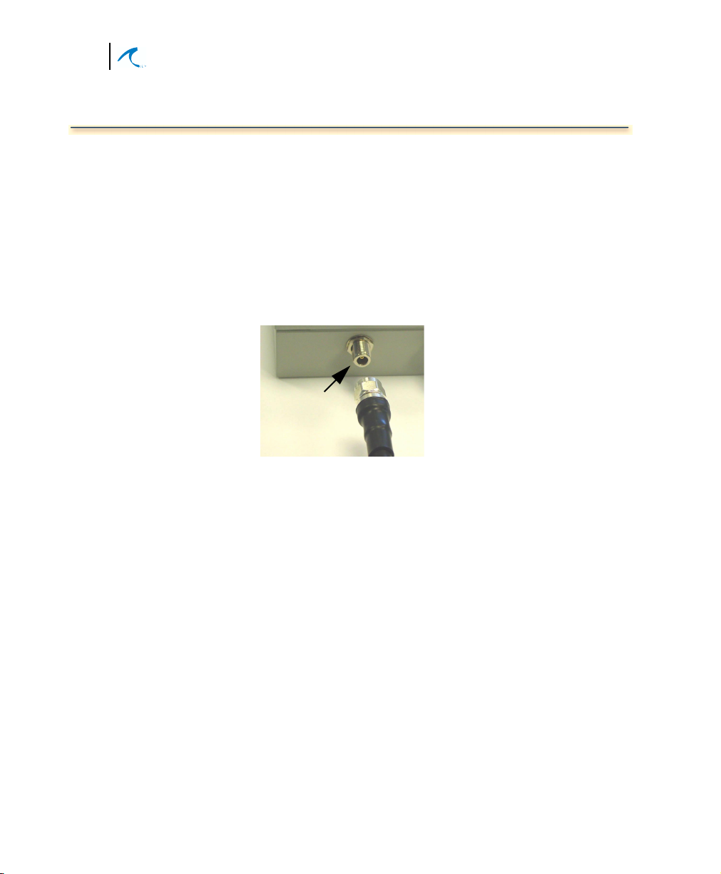
Connecting the Antenna to ODU
1. Place the end of the antenna cable next to the coax
connector on the bottom of the ODU. (The other
end is already connected to the antenna’s coax
connector from the earlier antenna installation.)
2. Thread the antenna cable male connector onto the
ODU coax connector and tighten enough to secure
the cable without overtightening.
See Figures 2-5 and 2-6 for reference.
Coax Connector
Antenna
Cable
Figure 2-6. Connecting antenna cable to ODU
Installation and Configuration
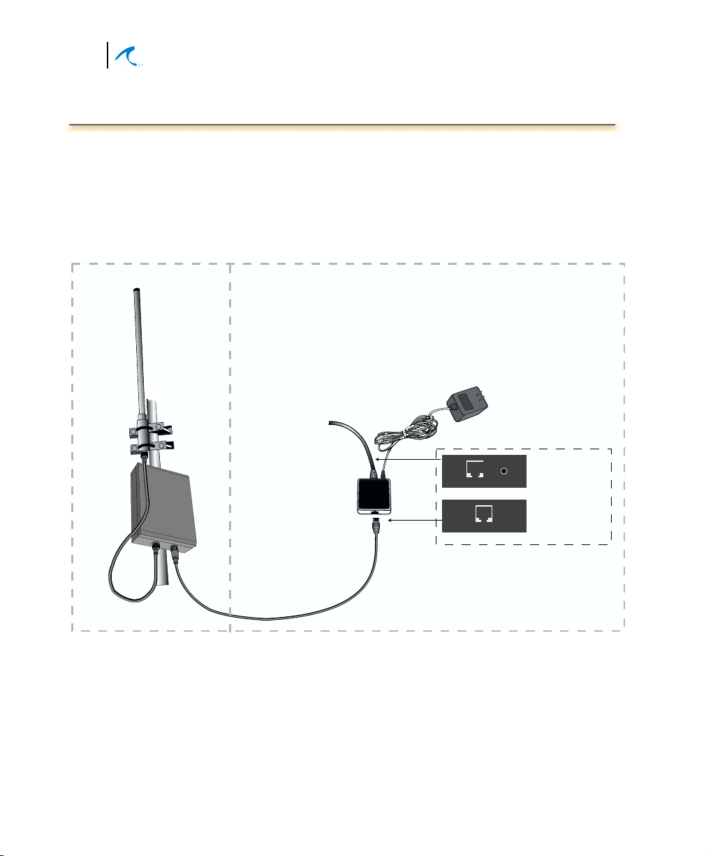
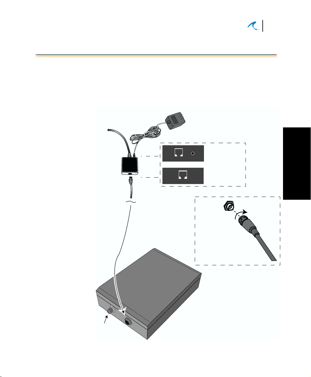
Connecting Ethernet and Power
Connecting Ethernet and Power
The Power Injector connects to the customer LAN (or a
single computer with web browser) and a source of AC
power via the supplied Power Injector AC Adapter. The
Power Injector also connects to the ODU via a single
PoE cable passing 10/100 Ethernet and DC power.
19
Standard Ethernet
Cable from Customer
LAN (data only)
with RJ45 Connector
Power Injector
PoE
Cable
to ODU
Power Injector AC Adapter
connects to 100/240VAC 50-60Hz
POWER INJECTOR CONNECTOR DETAIL
RJ45
RJ45
DETAIL
Special PoE Ethernet
Cable carries data
and Power to ODU.
RJ45-end connects to Power Injector
and circular multi-pin connector
attaches to ODU-end
Ethernet to LAN-side
Power
(label is marked
"To 10/100 LAN")
Ethernet to ODU-side
(label is marked
"To AirMAX ODU")
Plug cable
into Connector
on ODU and then
rotate cable connector
to lock it in place
CAUTION:
Connect all cables and complete the
installation BEFORE applying power
to ensure safety of personnel and
prevent damage to equipment.
Installation
2
Antenna
Coax
Connector
Figure 2-7. Power Injector Connections
 Loading...