

Malibu Boats Sportster, Response, Response LXi, Wakesetter, Sunsetter User Manual

i
All information and specifications included in this manual were in effect at the time of
approval for printing. Malibu Boats West, Inc. reserves the right, however, to discontinue
or change specifications or design at any time without notice and without incurring any
obligation.
Trademarks
Malibu, The Malibu Logo is a registered trademark of Malibu Boats West, Inc.
Indmar, Indmar is a registered trademark of Indmar Products Co., Inc.
All other product names are copyright and registered trademarks/trade names of their
respective owners.
© 2000, 2001, 2002, 2003, 2004, 2005 Malibu Boats West, Inc. All Rights reserved.
Printed in the USA

ii

CONTENTS. . . . . . . . . . . . . . . . . . . . . iii
TABLE OF FIGURES. . . . . . . . . . . . . iv
INTRODUCTION. . . . . . . . . . . . . . . . . v
CERTIFICATIONS & STANDARDS. . . v
MODEL SPECIFICATIONS . . . . . . . vi
BOATING SAFETY . . . . . . . . . . . . . 1-1
General Precautions . . . . . . . . . . . . 1-1
Safety Statements. . . . . . . . . . . . . . 1-1
Regulations. . . . . . . . . . . . . . . . . . . 1-2
Responsibilities . . . . . . . . . . . . . . . 1-2
Emergencies. . . . . . . . . . . . . . . . . . 1-4
Hazardous Conditions . . . . . . . . . . 1-5
Carbon Monoxide. . . . . . . . . . . . . . 1-6
Operation By Minors . . . . . . . . . . . 1-7
Passenger Safety. . . . . . . . . . . . . . . 1-7
Basic Rules Of The Road. . . . . . . . 1-7
FEATURES & CONTROLS. . . . . . . 2-1
Standard Gauges. . . . . . . . . . . . . . . 2-2
Circuit Breakers . . . . . . . . . . . . . . . 2-7
Switches & Indicators . . . . . . . . . . 2-7
Throttle Control . . . . . . . . . . . . . . . 2-9
Steering System . . . . . . . . . . . . . . . 2-9
Emergency Engine Stop Switch. . 2-10
Motorbox Cover. . . . . . . . . . . . . . 2-10
Driver’s Seat. . . . . . . . . . . . . . . . . 2-11
Integral Self Draining
Ice Chest . . . . . . . . . . . . . . . . . 2-11
Sundeck . . . . . . . . . . . . . . . . . . . . 2-11
V-Drive Engine Access
Hatch. . . . . . . . . . . . . . . . . . . . 2-12
Ski Pylon . . . . . . . . . . . . . . . . . . . 2-12
Swim Platform . . . . . . . . . . . . . . . 2-13
Navigational Lights . . . . . . . . . . . 2-13
Storage Areas. . . . . . . . . . . . . . . . 2-14
Drain Plugs. . . . . . . . . . . . . . . . . . 2-14
Speedometer Pickup. . . . . . . . . . . 2-15
Tilt Steering Wheel . . . . . . . . . . . 2-15
Exhaust. . . . . . . . . . . . . . . . . . . . . 2-16
Ventilation . . . . . . . . . . . . . . . . . . 2-16
Optional Equipment. . . . . . . . . . . 2-17
Wedge. . . . . . . . . . . . . . . . . . . . . . 2-20
Warning Labels . . . . . . . . . . . . . . 2-21
OPERATION . . . . . . . . . . . . . . . . . . . 3-1
Trailering . . . . . . . . . . . . . . . . . . . . 3-1
Fueling . . . . . . . . . . . . . . . . . . . . . . 3-4
Starting. . . . . . . . . . . . . . . . . . . . . . 3-4
Shifting/Running . . . . . . . . . . . . . . 3-6
Steering . . . . . . . . . . . . . . . . . . . . . 3-6
Stopping . . . . . . . . . . . . . . . . . . . . . 3-8
Docking . . . . . . . . . . . . . . . . . . . . . 3-9
High Speed Operation . . . . . . . . . 3-10
Towing A Skier . . . . . . . . . . . . . . 3-11
Towing Another Boat. . . . . . . . . . 3-13
Anchoring. . . . . . . . . . . . . . . . . . . 3-13
Propellers . . . . . . . . . . . . . . . . . . . 3-13
Malibu Exclusive Adjustable
Rudder System . . . . . . . . . . . . 3-14
Corrosion Protection . . . . . . . . . . 3-15
CARE AND MAINTENANCE. . . . . 4-1
Interior . . . . . . . . . . . . . . . . . . . . . . 4-1
Exterior. . . . . . . . . . . . . . . . . . . . . . 4-2
Engine/Drive Train. . . . . . . . . . . . . 4-4
Fuel System . . . . . . . . . . . . . . . . . . 4-6
Electrical . . . . . . . . . . . . . . . . . . . . 4-7
Miscellaneous. . . . . . . . . . . . . . . . . 4-9
Troubleshooting . . . . . . . . . . . . . . 4-12
Warranty Information. . . . . . . . . . 4-15
Glossary . . . . . . . . . . . . . . . . . . . . 4-19
Index. . . . . . . . . . . . . . . . . . . . . . . 4-20
iii
CONTENTS

iv
TABLE OF F
IGURES
Figure 1-1 Personal Flotation
Devices. . . . . . . . . . . . . . . . . . . . . 1-3
Figure 1-2 Fire Extinguisher . . . . . . . . 1-3
Figure 1-3 Weather Hazards . . . . . . . . 1-5
Figure 1-4 Diver Down Flag . . . . . . . . 1-5
Figure 1-5 Carbon Monoxide
Hazards. . . . . . . . . . . . . . . . . . . . . 1-6
Figure 1-6 Regulatory Markers. . . . . . 1-8
Figure 1-7 Buoy Shapes . . . . . . . . . . . 1-9
Figure 1-8 Spherical Marker . . . . . . . . 1-9
Figure 1-9 Day Markers . . . . . . . . . . . 1-9
Figure 1-10 Crossing Situation . . . . . 1-10
Figure 1-11 Overtaking
Another Craft . . . . . . . . . . . . . . . 1-11
Figure 2-1 General Layout
V-Drive Boats. . . . . . . . . . . . . . . . 2-1
Figure 2-2 General Layout
Direct Drive Boats . . . . . . . . . . . . 2-1
Figure 2-3 Tachometer/Hourmeter . . . 2-2
Figure 2-4 Speedometer Calibrate and
Display Selection Switches . . . . . 2-2
Figure 2-5 Speedometer . . . . . . . . . . . 2-2
Figure 2-6 Multi Gauge. . . . . . . . . . . . 2-5
Figure 2-7 Circuit Breaker Panel. . . . . 2-7
Figure 2-8 Accessory Switch Panel. . . 2-7
Figure 2-9 V-Drive Warning Light . . . . 2-8
Figure 2-10 Throttle . . . . . . . . . . . . . . 2-9
Figure 2-11 Stop Switch Lanyard . . . 2-10
Figure 2-12 Motorbox . . . . . . . . . . . . 2-10
Figure 2-13 Bolster Seat . . . . . . . . . . 2-11
Figure 2-14 Lumbar Adjuster . . . . . . 2-11
Figure 2-15 Seat Adjuster . . . . . . . . . 2-11
Figure 2-16 Sundeck . . . . . . . . . . . . . 2-11
Figure 2-17 Engine Access Hatch. . . 2-12
Figure 2-18 Pi vot ing -Head Ski Pylon . . 2-12
Figure 2-19 Swim Platform. . . . . . . . 2-13
Figure 2-20 Swim Platform Pins. . . . 2-13
Figure 2-21 Bow Light . . . . . . . . . . . 2-13
Figure 2-22 Lockable Transom
Storage . . . . . . . . . . . . . . . . . . . . 2-14
Figure 2-23 Transom Drain Plug. . . . 2-14
Figure 2-24 Bilge Drain Plug . . . . . . 2-15
Figure 2-25 Thru-Hull Paddle
Wheel Pickup . . . . . . . . . . . . . . . 2-15
Figure 2-26 Tilt Steering. . . . . . . . . . 2-15
Figure 2-27 Heater. . . . . . . . . . . . . . . 2-17
Figure 2-28 Boat Cover. . . . . . . . . . . 2-17
Figure 2-29 Bimini Top Screw . . . . . 2-18
Figure 2-30 Strap Eyelet . . . . . . . . . . 2-18
Figure 2-31 Stereo Location
(Arm Rest) . . . . . . . . . . . . . . . . . 2-18
Figure 2-32 Stereo Remote Control
Panel. . . . . . . . . . . . . . . . . . . . . . 2-18
Figure 2-33 Shower Head . . . . . . . . . 2-19
Figure 2-34 Shower Valve. . . . . . . . . 2-19
Figure 2-35 Pull-Up Cleat. . . . . . . . . 2-19
Figure 2-36 SaniPottie. . . . . . . . . . . . 2-19
Figure 2-37 Wedge Down . . . . . . . . . 2-20
Figure 2-38 Wedge Up . . . . . . . . . . . 2-20
Figure 2-39 Scarpa Suppression
Plate (SSP) . . . . . . . . . . . . . . . . . 2-20
Figure 2-40 Warning Labels . . . . . . . 2-21
Figure 3-1 Trailer Hitch. . . . . . . . . . . . 3-1
Figure 3-2 Safety Chains. . . . . . . . . . . 3-2
Figure 3-3 Bow Tie-Down . . . . . . . . . 3-2
Figure 3-4 Transom Tie-Down . . . . . . 3-2
Figure 3-5 Fueling. . . . . . . . . . . . . . . . 3-4
Figure 3-6 Throttle Positions. . . . . . . . 3-6
Figure 3-7 Turning With A Rudder. . . 3-7
Figure 3-8 Stern Push . . . . . . . . . . . . . 3-8
Figure 3-9 Docking With
Wind/Current . . . . . . . . . . . . . . . . 3-9
Figure 3-10 Hand Signals . . . . . . . . . 3-12
Figure 3-11 Towing . . . . . . . . . . . . . . 3-13
Figure 3-12 Propeller. . . . . . . . . . . . . 3-14
Figure 3-13 Adjustable Rudder. . . . . 3-14
Figure 4-1 Typical Transmission
Dipstick . . . . . . . . . . . . . . . . . . . . 4-4
Figure 4-2 In-Line Fuel Filter . . . . . . . 4-5
Figure 4-3 Main Circuit Breaker. . . . . 4-6
Figure 4-4 Battery Level . . . . . . . . . . . 4-7

v
INTRODUCTION
Over the years, you have watched us grow into one of the most respected boat builders in
the world. And undoubtedly, somewhere, you have run into at least one Malibu owner
who proudly speaks of the “Malibu Difference.” That difference they so proudly speak
of could be the special way we have serviced them over the years. We call it “going the
distance.” Or maybe they are referring to the way their Malibu consistently outperforms
other ski boats that they have driven. We can’t deny that we are different. Our passion for
building the perfect ski boat is only surpassed by our commitment to total customer
satisfaction.
This manual has been assembled to help you operate your new Malibu with safety and
pleasure. Details of typical equipment as well as recommended safety and maintenance
procedures about your boat are supplied. Please read carefully and familiarize yourself
with the craft before using it.
We at Malibu Boats thank you for choosing us as your boat manufacturer and assure you
that your satisfaction and boating enjoyment will continue to be our #1 priority.
C
ERTIFICATIONS
& STANDARDS
NMMA Certification
Your Malibu boat has been built to meet or exceed the standards set by the National
Marine Manufacturers Association (NMMA). NMMA verifies annually, or whenever a
new boat model is introduced, to determine that they meet not only Coast Guard
regulations, but also the more comprehensive standards set by the American Boat &
Yacht Council (ABYC).
Standards To Which This Boat Was Built
Your Malibu boat was built with the utmost care throughout the complete manufacturing
process. The deck, hull, stringers and floor, as well as many accessory components, were
built using our hand-laid composite fiberglass scheduling techniques. All boats receive
complete quality control checks. Each boat is lake tested, and all information is kept on
file at our factory for future reference.
Hull Identification Number (HIN)
Your Hull Identification Number can be found on the starboard transom of your boat
below the rubber rub rail. Federal law prohibits the tampering or removing of the number
in any way. Use this number to register your boat with your local and state authorities.
US MB2GXXXXA001
vi
MODEL SPECIFICATIONS
Sportster Response Response Wakesetter Sunsetter/
Series Series LXi Wakesetter
Length 20' 20' 20' 6" 21' 21'
Beam 86" 90" 93" 93" 93"
Draft 14" 16" 16" 18" 18"
Weight 2100 lbs 2450 lbs 2800 lbs 2800 lbs 2800 lbs
Fuel Cap. 38 Gal. 35 Gal. 41 Gal. 41 Gal. 37 Gal.
Seating Cap. 6/8 6/8 8 10 10
Std. Engine 310 Vortec 310 Vortec Vortec 310 Vortec 310 Vortec
Std. Gelcoat 3 4 3 3 3
Ballast Weight N/A N/A N/A
Std. Prop. 3 Blade ACME 3 Blade ACME 3 Blade ACME 3 Blade ACME 3 Blade ACME
Sunsetter Sunscape/ Sunscape/ Sunsetter/ Sunscape
LXi Wakesetter Wakesetter Wakesetter 25
21 LSV 23 LSV XTi
Length 21'8" 21' 22'6" 22'6"" 25'
Beam 93" 93" 96" 96" 102"
Draft 18" 18" 24" 24" 26"
Weight 2900 lbs 2900 lbs 3400 lbs 3300 lbs 4500 lbs
Fuel Cap. 35 Gal. 35 Gal. 55 Gal. 43 Gal. 80 Gal.
Seating Cap. 10 11 12 12 14
Std. Engine 310 Vortec 340 340 340 8.1Liter / 425 HP
Std. Gelcoat 4 4/3 4/3 4/3 3
Ballast Weight
Std. Prop. 3 Blade ACME 4 Blade ACME 4 Blade ACME 3 Blade ACME 4 Blade ACME
1-1
Chapter 1
BOATING S
AFETY
At Malibu, safety is not an option!
General Precautions
Your Malibu boat has been constructed to meet all U.S. Coast Guard and National Marine
Manufacturers Association (N.M.M.A.) requirements. However, it is still your
responsibility as the boat owner to ensure the boat is always operated in a safe fashion.
U.S. Coast Guard regulations require certain safety equipment be present on your boat
during operation. Besides the U.S. Coast Guard regulations, other local and/or
international law enforcement agencies may have similar requirements. You should check
with your local marine enforcement agency regarding any such requirements before using
the waterways.
It is not intended for this manual to be a replacement for a course on boating safety. It is
highly recommended that if you are unfamiliar with the use and operation of a boat, you
seek advice and training from a qualified individual or organization. Check with your
local boating agency or Malibu dealer for more information about boating safety classes
in your area.
Safety Statements
Throughout this manual, specific precautions and symbols identify safety related
information. Follow these precautions as indicated.
The Safety Alert symbol means Attention! Become Alert! Your Safety Is
Involved!
Indicates an imminently hazardous situation that, if not
avoided, will result in death or serious injury.
Indicates a potentially hazardous situation that, if not
avoided, could result in death or serious injury.
Indicates a potentially hazardous situation that, if not avoided,
could result in minor or moderate injury or property damage. It
may also be used to alert against unsafe practices.
Notice: Indicates installation, operation or maintenance information
which is important but not hazard related.
1
1-2
The precautions listed in this manual and on the boat are not all-inclusive. If a procedure
or method is not specifically recommended, you must satisfy yourself that it is safe for
you and your passengers, and that the boat will not be damaged or made unsafe as a result
of your decision. Remember — always use common sense when operating your boat!
Regulations
The U.S. Coast Guard is the governing authority of the waterways and is there to help the
boating public. State boating regulations are enforced by local authorities. You are subject
to marine traffic laws and “Rules of the Road” for both federal and state waterways; you
must stop if signaled to do so by enforcement officers and permit to be boarded, if asked.
Responsibilities
Registration
Federal Law requires that all motorboats be registered and that all motorcraft not
documented by the U.S. Coast Guard display registration numbers. In nearly all states,
this means registration with the designated state agency. In a few jurisdictions, the Coast
Guard retains registration authority. Your Malibu dealer will either supply registration
forms or tell you where they may be obtained. The agency will supply you with a
certificate which must be carried with you when the boat is in operation.
Education
If you have never owned a boat before you can get an excellent introduction to boat
handling from organizations such as the U.S. Coast Guard and American Red Cross.
Even if you are a veteran boater, these courses will help sharpen your boating skills as
well as bring you up to date on current rules and regulations. See your local boating
agency or Malibu dealer for information on classes in your area.
Insurance
The boat owner is legally responsible for damages or injuries he or she causes. Common
sense dictates that you carry adequate personal liability and property damage insurance
on your boat, just as you would on your automobile. You should also protect your
investment from physical damage or theft.
1-3
Safety Equipment
U.S. Coast Guard regulations require certain accessory equipment on each boat. For a
detailed description, obtain “Federal Requirements for Recreational Boats” published by
the Coast Guard.
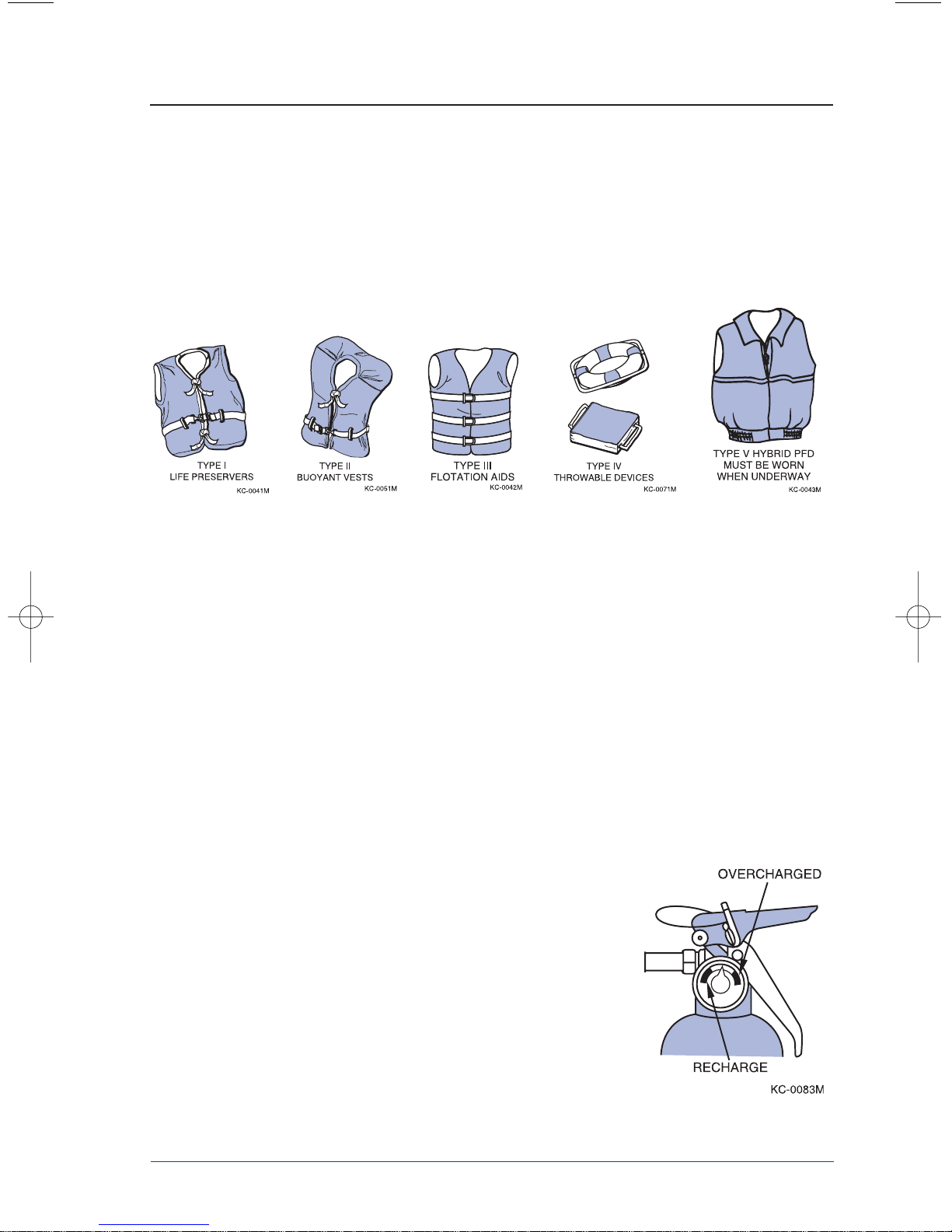
1) Personal Flotation Devices (PFDs): PFDs must be Coast Guard approved, in
good and serviceable condition and the appropriate size for the user. It is
recommended that you wear PFDs while your boat is underway.
Figure 1-1. Personal Flotation Devices
Boats more than 16 feet in length must be equipped with one type I, II, III or V
and one type IV. PFDs are intended to save lives; you and your passengers
should wear them while in the boat. Learn how to use them and adjust as
necessary to make comfortable to wear. The type II PFD is recommended for
near shore or inland water use. Some PFDs are specially made for use while
waterskiing and can handle impacts if a skier has fallen.
Notice: If a type V PFD is to be counted toward the minimum carriage
requirements, it must be worn.
2) Emergency Stop Switch: Factory installed lanyard emergency stop switch. It is
highly recommended that you use this switch since it can prevent your boat from
becoming a runaway. (See page 2-13 for specific use.)
3) Fire Extinguishers: A fire extinguisher is required
if your boat has an inboard engine, or when fuel is
stored in closed stowage compartments.
Approved fire extinguishers are classified by a
letter symbol, either B-I or B-II with the B
designating that the material will extinguish
flammable liquids such as gasoline, oil, etc. B-I
extinguishers are required for boats less than 26
feet in length. Check periodically to insure that
the extinguisher is in working condition and fully
charged.
Figure 1-2. Fire Extinguisher

1-4
4) Navigation Lights: Recreational boats are required to display navigational lights
between sunset and sunrise and other periods of reduced visibility (fog, rain,
haze, etc.). Your navigation lights are provided to keep other boats informed of
your presence and course. It is up to you to make sure they are operational and
turned on when required.
Emergencies
Giving Assistance
Many of the distress calls are not true emergencies. In most cases the boat is disabled for
one reason or another, but there is no immediate danger of death or serious injury.
However, emergencies can occur and you should know how to cope with them. If you
observe a boat in distress, assume it is a true emergency. Proceed to the scene and render
assistance. Federal law requires boat operators to offer assistance and aid to others. The
law’s “Good Samaritan” clause absolves you from any civil liability in the event that your
assistance causes injury or property damage.
There is a way to handle nearly every emergency if you don’t panic. Learn your boating
lessons and safety procedures well, and you will have the confidence and ability to
handle an emergency should one arise.
Fires
Many boat fires involve flammable liquids such as gas or oil. Many inboard fires start in
the bilge area which at times can be filled with gas vapors. Since gas vapors cannot be
seen, boat fires tend to travel very fast. If you encounter a fire onboard, turn off the
engine immediately. If you have a fire extinguisher onboard and access to the fire, it may
be controllable. Direct the contents of the extinguisher at the base of the flames. Throw
burning materials overboard if possible. Put on PFDs if not already on, signal for help
and prepare to abandon the boat if necessary.
Reporting
Boat operators are required by law to file a Boating Accident report with their state
boating law enforcement agency when their boat is involved in certain boating accidents.
A boating accident must be reported if there is a loss or probable loss of life, personal
injury requiring medical attention, damage exceeding $500, or there is a complete loss of
the boat. If any of these conditions arise seek further assistance from local law
enforcement personnel.
1-5
Hazardous Conditions
Every waterway poses hazards that should be avoided. The following information
outlines some of the hazards which may be encountered.
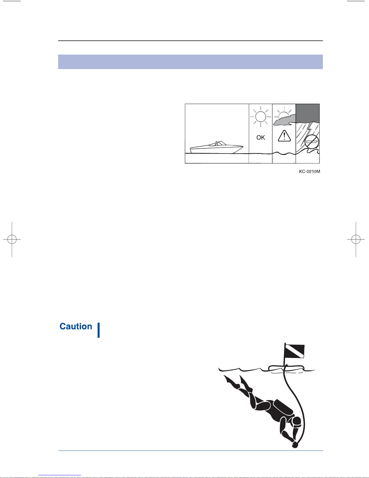
Weather
Learn and understand weather patterns
and signs of change. Bad weather can
cause an uncomfortable and unsafe
situation. If a storm approaches seek a
safe harbor.
Figure 1-3. Weather Hazards
Dam Spillways
The area around dam spillways is very hazardous and conditions can change rapidly. Stay
clear of the spillways and areas below dams.
Weeds
Weeds can generally be a threat to a boat’s engine and other components on the boat. If
weeds wrap around the propeller they can create vibration in the engine. They also
restrict water intake, causing the engine to overheat, and can clog speedometer pickup
tubes, affecting correct speedometer readings.
Shallow Water Operation
Shallow water brings on obvious hazards such as sand bars, stumps, rocks, etc. Know the
area you will be operating the boat in. Hitting objects at high speeds can cause severe
damage to people and the boat. If you know you will be navigating the boat in shallow
water, post a lookout and proceed slowly.
Know the minimal depth your boat can safely travel.
Damage to underwater gear caused by shallow water
maneuvering is not covered by your warranty.
Warning Markers
Learn to recognize the different buoys and day
markers; they are used as the signposts of the
waterways identifying navigable routes and water
hazards. It is a good idea to ask local authorities
about hazard areas and if they are marked. Stay
within boundaries and clear of hazards.
Figure 1-4. Diver Down Flag
KC-0250M
1-6
Carbon Monoxide
Carbon Monoxide (CO) is a colorless and odorless gas produced by all engines and fuel
burning appliances. Even with the best boat design and construction, plus the utmost care
in inspection, operation, and maintenance, hazardous levels of CO may still be present in
accommodation spaces under certain conditions. To reduce CO accumulation, always
ventilate the boat interior and avoid boating situations which cause increased exposure.
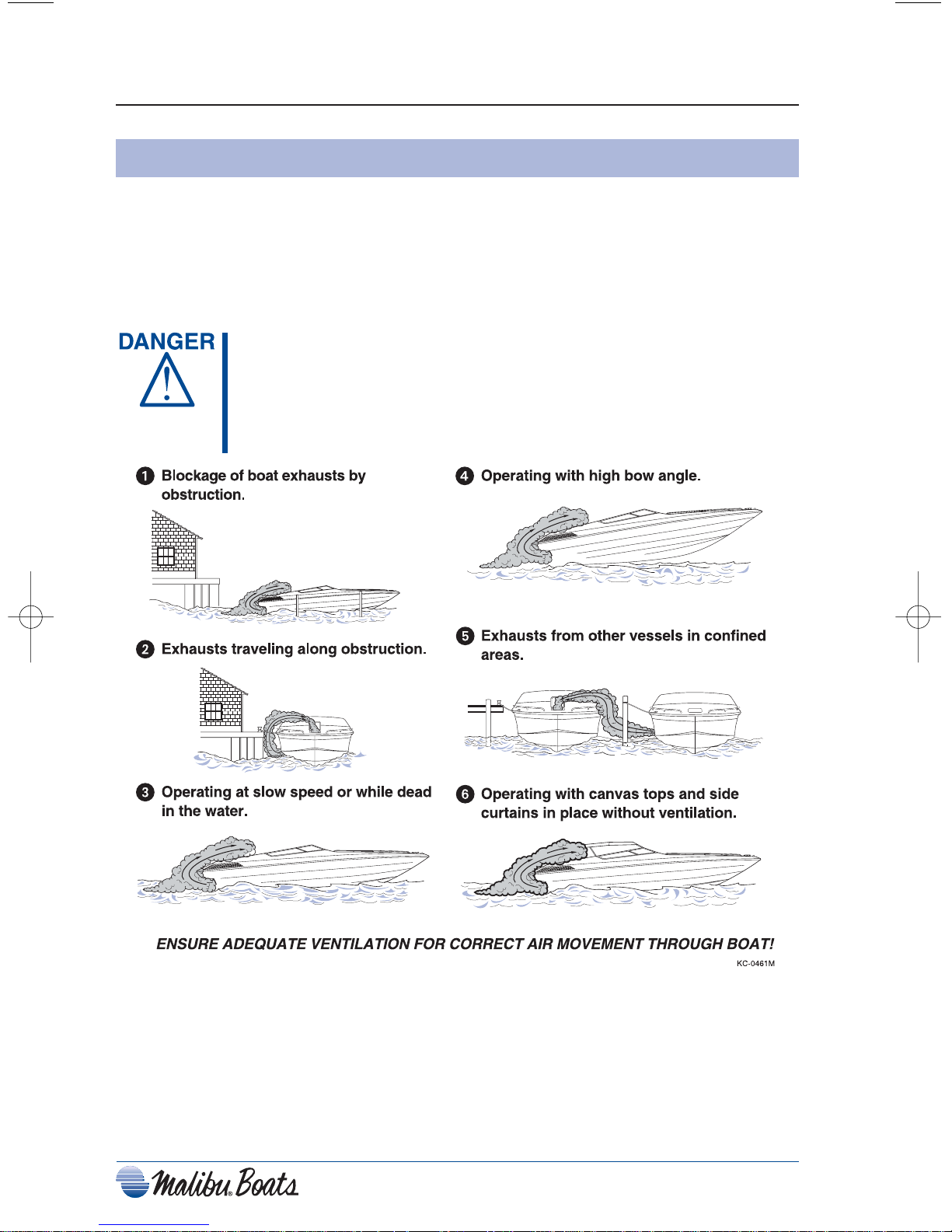
EXTREME HAZARD – Carbon monoxide gas (CO) is colorless,
odorless and extremely dangerous. All engines and fuel
burning appliances produce CO as exhaust. Direct and
prolonged exposure to CO will cause BRAIN DAMAGE or
DEATH. Signs of exposure to CO include nausea, dizziness
and drowsiness. Sources of CO include:
Figure 1-5. Carbon Monoxide Hazards
1-7
Operation By Minors
If your boat will be operated by a minor, remember to have an adult present at all times.
Many states have laws regarding minimum age and licensing requirements for minors.
Contact state and local authorities for special requirements that may apply in your area.
Passenger Safety
Any time you take your boat out, make sure that there is at least one other passenger
aboard who is familiar with the operation of your boat. Passengers should be well aware
of emergency equipment and shown how to use it. Passengers should also keep hands and
feet in the boat and be safely seated while the boat is in motion.
Your boat should never be operated while you are under the influence of alcohol or drugs.
Reaction times can be reduced and judgment affected creating situations that can be very
dangerous.
Federal and state laws prohibit operating a boat under the
influence of alcohol and other drugs. These regulations are
actively enforced. Impaired operation may result in severe
personal injury or death.
Basic Rules Of The Road
The nautical rules of the road must be followed to prevent
collisions between vessels. Like traffic laws for automobiles,
the operator is legally required to follow the rules.
The following information outlines only the most basic of the nautical rules of the road.
For more information, contact your local U.S. Coast Guard Auxiliary.
Aids to Navigation
Learn to recognize the different buoys and day markers; they are the signposts of the
waterway. There are 2 primary marking systems in use in the U.S.: the Uniform State
Waterway Marking System (USWMS) used on inland waters and maintained by each
state, and the Federal Waterway Marking System (FWMS) used on coastal waters and
rivers and maintained by the U.S. Coast Guard (USCG). In addition, the FWMS has two
modified systems; Western River Buoyage, and Intracoastal Waterway Buoyage. Be sure
to check with local authorities on the buoyage system in use.
The type of hazard/warning buoys and markers depends on the area of jurisdiction. Check
with local boating authorities.
USWMS System
In the USWMS Lateral System, well defined channels are marked with red and black
buoys. Lateral means the sides of the channel are marked and the boat should pass
between them.
The USWMS Cardinal System is used when there is no well defined channel or where an
obstruction may be approached from more than one direction. With the cardinal system:
• Pass north or east of BLACK-TOPPED WHITE buoy.
• Pass south or west of RED-TOPPED WHITE buoy.
• RED and WHITE VERTICALLY STRIPED buoy indicates boat should pass
outside of the buoy (away from shore).
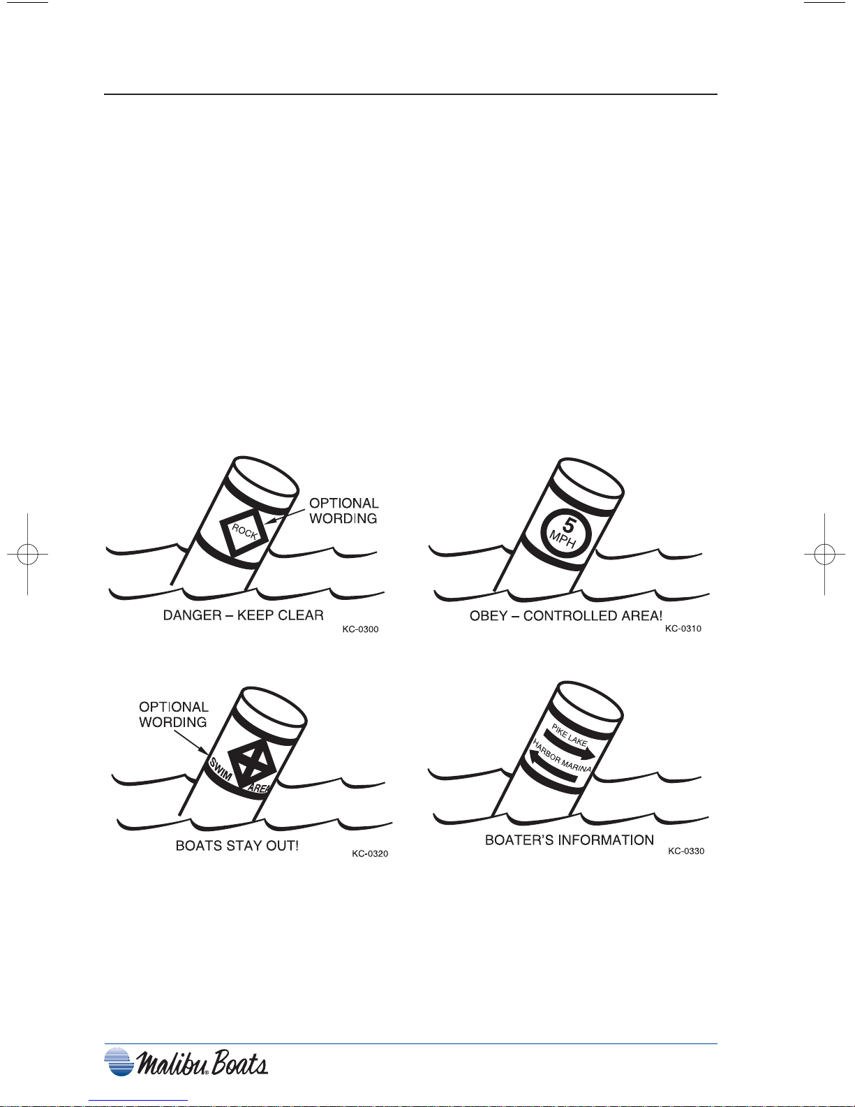
Uniform State Regulatory Markers
USWMS regulatory markers are white with international orange geometric shapes; you
must obey regulatory markers.
Figure 1-6. Regulatory Markers
1-8
1-9
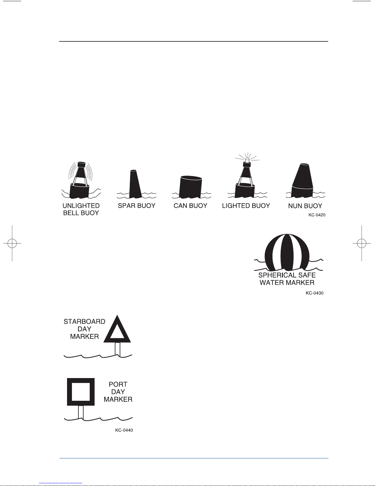
FWMS System
The FWMS Lateral System is for use on navigable waters except Western Rivers and
Intracoastal Waterways.
The markings on these buoys are oriented from the perspective of being entered from
seaward (the boater is going towards the port). This means that red buoys are passed on the
starboard (right) side of the vessel when proceeding from open water into port, and green
buoys to the port (left) side.
The right side (starboard) of the channel is marked with RED, even numbered buoys. The
left (port) side of the channel is marked with GREEN, odd numbered buoys.
Figure 1-7. Buoy Shapes
The middle of the channel is marked with RED and
WHITE vertically striped buoys; pass close to these buoys.
Obstructions, channel junctions, etc. are marked with RED
and GREEN horizontally striped buoys.
A RED band at the top means the preferred channel is to
the left of the buoy; a GREEN top band means the
preferred channel is to the right of the buoy.
Figure 1-8. Spherical Marker
Day markers are colored and numbered the same as buoys.
RED, triangular day markers with even numbers mark the
starboard side of the channel. GREEN, square day markers
with odd numbers mark the port side of the channel.
Lights, bells and horns are used on buoys for night or poor
visibility conditions.
Figure 1-9. Day Markers
1-10
Right-Of-Way
Notice: In general, boats with less maneuverability have right-of-way
over more agile craft. You must stay clear of the vessel with
right-of-way and pass to his stern.
Privileged Boats
Privileged boats have right-of-way
and can hold course and speed.
Sailboats and boats paddled or rowed
have the right-of-way over motor
boats. Sailboats under power are
considered motorboats. Small
pleasure craft must yield to large
commercial boats in narrow channels.
Burdened Boats
The burdened boat is the boat that
must make whatever adjustments
to course and speed necessary to
keep out of the way of the
privileged boat.
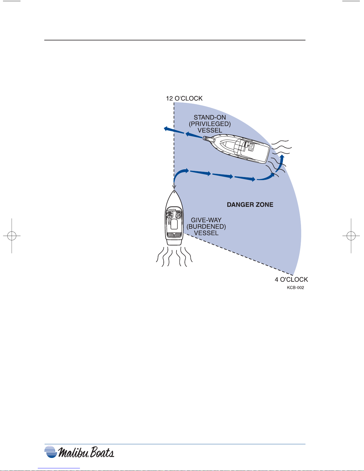
Crossing Situation
In crossing situations, the boat to
the right from the 12 o’clock to
the 4 o’clock position has the
right-of-way. It must hold
course and speed. The
burdened boat keeps clear and
passes behind the privileged
boat. Boats going up and down a river have
the privilege over boats crossing the river.
Figure 1-10. Crossing Situation
Meeting Head-On
Neither boat has the right-of-way in this situation. Both boats should decrease speed,
should turn to the right, and pass port-to-port. However, if both boats are on the left side
of a channel, each vessel should sound two short horn blasts and pass starboard to
starboard.
1-11
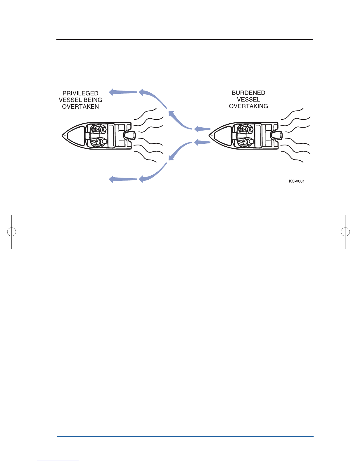
Overtaking
The boat that is overtaking one ahead of it is the burdened boat and must make any
adjustments necessary to keep out of the way of the privileged boat.
Figure 1-11. Overtaking Another Craft
The General Prudential Rule
The general prudential rule regarding right-of-way is that if a collision appears
unavoidable, neither boat has right-of-way. As prescribed in the Rules of the Road, both
boats must act to avoid collision.
Night Running
Boats operating between sunset and sunrise (hours vary by state) must use navigational
lights. Nighttime operation, especially during bad weather or fog can be dangerous. All
Rules of Road apply at night, but it is best to slow down and stay clear of all boats,
regardless of who has right-of-way. Protect your night vision by avoiding bright lights
and have a passenger, if possible, help keep watch for other boats, water hazards, and aids
to navigation.

1-12
Chapter 2
FEATURES & C
ONTROLS
No other ski boat manufacturer incorporates in their
product as many innovative and technically advanced
features as Malibu.
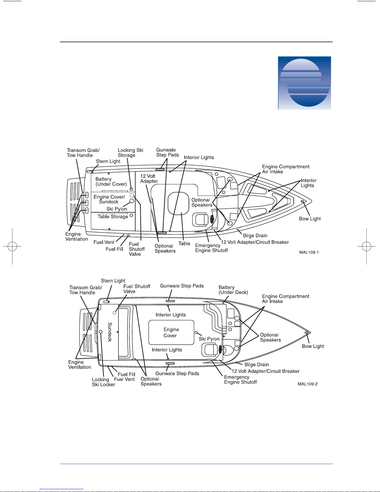
Figure 2-1. General Layout V-Drive Boats
Figure 2-2. General Layout Direct Drive Boats
2-1
2
Standard Gauges
The following standard gauges are included on all
models. It is important for the safe and proper operation
of your boat to fully understand these gauges.
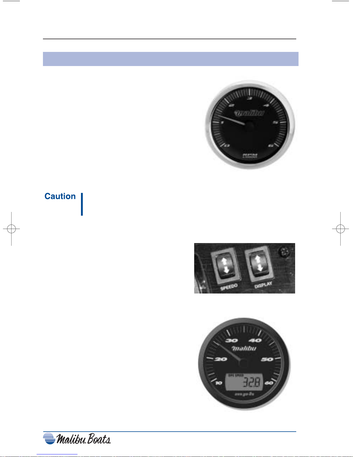
Tachometer
Located top right of the dash panel the tachometer
registers the operating speed of your engine in
revolutions per minute (RPM). This gauge is used to
provide you with information needed to ensure the
operation of the engine is kept within engine
manufacturer’s proper range of operation. Be sure to
consult your engine manual for the correct range of
operation for your particular model.
Do not operate your boat beyond the recommended RPM
range. Doing so could cause irreversible problems, and may
not be covered under your engine warranty.
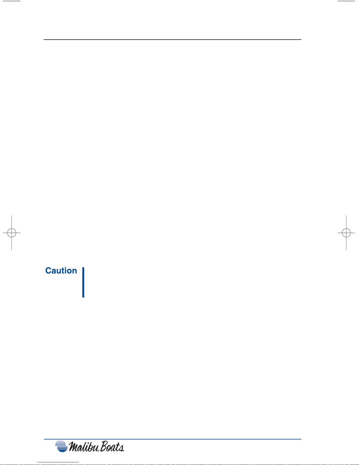
Speedometer
The speedometer registers speed in miles per
hour (MPH). The speedometer system consists of
a thru-hull paddle wheel speed sensor that
records water movement, a computer located
under the dash that converts the information, an
analog readout on the dash, and the interconnecting wiring. The speedometers are
calibrated at the factory and will not normally
need additional adjustment, however, from time
to time it may be necessary to re-calibrate. The
speedometers can be adjusted using the SPEEDO
rocker switch located to the right of the steering
wheel. Please refer to Speedometer Calibration
below for the adjustment procedure.
2-2
Figure 2-5. Speedometer
Figure 2-3. Tachometer/Hourmeter
Figure 2-4. Speedometer Calibrate
and Display Selection Switches

Speedometer Calibration
To quickly recalibrate to AWSA official tournament rules, you will need an accurately
measured ski course of 850 feet and a certified stopwatch accurate to a thousandth of a
second.
1. Approach the course at a speed of 36 MPH. Hold the speed steady and have observer
check the course with the stopwatch as you pass through the beginning of the course.
2. The course time should be between 15.88 and 16.28 seconds. No adjustments are
necessary if within this tolerance.
3. If the course time is not within this tolerance, adjust the rocker switches up or down
until you are calibrated.
Multi Function Display Panel
Located in the lower panel of the speedometer gauge is an LCD display panel that allows
an assortment of standard and optional features to be displayed. To find each feature,
scroll through the screens by depressing the up arrow of the DISPLAY rocker switch
found to the right of the steering wheel, until desired feature is located. Each function
will stay displayed until another is chosen.
Notice:
Use only the up arrow to scroll through each feature, do
not use the down arrow. The down arrow is used to adjust
the functions of the feature chosen. Below is a list of
standard and optional features that can be displayed.
Feature 1: Digital Clock Display
Set to display current time. To adjust, press and hold the down arrow of the DISPLAY
switch for three seconds or until the colon (:) stops flashing. Continue to hold button
down until correct hours are set. Press the up arrow to set minutes. One push of the
button will set time by one minute increments, holding the button will set the minutes by
ten minute increments. No change for three seconds will revert the clock to standard
operation.
Feature 2: Hour Meter Display
Notice:
Hours only accumulate when engine is above 300 rpm.
The hour meter acts as an odometer for the engine. Use the hour meter to identify how
much your boat is being used and what time you will need to perform required and
recommended maintenance at the proper intervals. No adjustment function is available
for this feature. Please refer to your engine manual to determine maintenance schedules.
Feature 3: Optional Water Depth Display
The optional water Depth feature will aid in finding shallow areas of water that may
cause damage to your boat if hit. The gauge will display the depth of the water relative to
the bottom of the boat and may also be programmed to sound an alarm at a predetermined depth. To check the depth of the water, use the up arrow of the DISPLAY
rocker switch to scroll to the Depth feature; the current depth will be displayed.
2-3
English/Metric Operation
Your Malibu Boat dash gauges will come from the factory in English mode. To convert to
Metric, while the LCD digital display is in hours, hold display button down for three
seconds. This will automatically convert to metric readings.
The unit comes from the factory with the alarm setting programmed to “0”. To change
the alarm depth, press and hold the down arrow of the DISPLAY rocker switch three (3)
seconds or until current depth alarm set point is displayed. Press and hold the up arrow on
the rocker switch to set desired alarm depth. An audible alarm will sound if you travel
within the set alarm depth. No change for three seconds will revert the Depth Gauge to
standard operation.
Feature 4: Air Temperature Display
The Air Temperature feature displays the ambient air temperature and is measured in
degrees Fahrenheit only. No adjustment function is available for this feature.
Feature 5: Lake Temperature Display
The Lake Temperature feature provides lake water temperature, and is measured in
degrees Fahrenheit only. No adjustment function is available for this feature.
Feature 6: Malibu Launch System (MLS) Ballast Tank Fill Level
All 23 Wakesetter LSV, Wakesetter 23 XTi, and 21.5 Wakesetter VLX come standard
with Ballast tank level displays. This display will give information for ballast water
amounts by displaying four readings: FULL, _ FULL, _ FULL, and Empty. To display
each tank capacity, scroll through each tank display beginning from front top tank, front
center bottom, left transom, and right transom.
Do not overfill tanks. Doing so can expand tank beyond
recommended capacity and cause failure to the tank and
pump fittings. Damage caused by overfilled tanks will not be
covered under your Malibu Warranty.
Compass Mode
Compass Mode is used to give directions in North, South, East and West. The orientation
for this feature is completed at the gauge manufacturer, and no adjustment is necessary.
Speed Mode
Displays the GPS speed with an update rate of once per second.
2-4
2-5
Speed Auto Cal
The speedometer can be calibrated automatically when the boat speed is between 15 and
36 MPH. To calibrate, select the GPS feature display. Press and hold the down arrow of
the DISPLAY rocker switch for three (3) seconds until “CAL“ is displayed. Continue to
hold button down until the display reads “DONE” or “FAIL”. If the LCD reads “DONE”,
the speedometer will automatically adjust to GPS speed. The LCD reads, “FAIL” for the
following reasons:
1. GPS speed was not within 15 - 36 MPH.
2. GPS was not steady ±3 MPH for 3 seconds.
GPS Failure Signals
If the GPS module is attached, but the LCD does not display, there is a problem with the
wiring or module. Please contact your local Malibu dealer for servicing.
If GPS fails during operation, it will display “NORES”, no response. Please contact your
local Malibu dealer for servicing.
If GPS module does not lock on to a GPS signal, the LCD will read “NOSIG”, no signal.
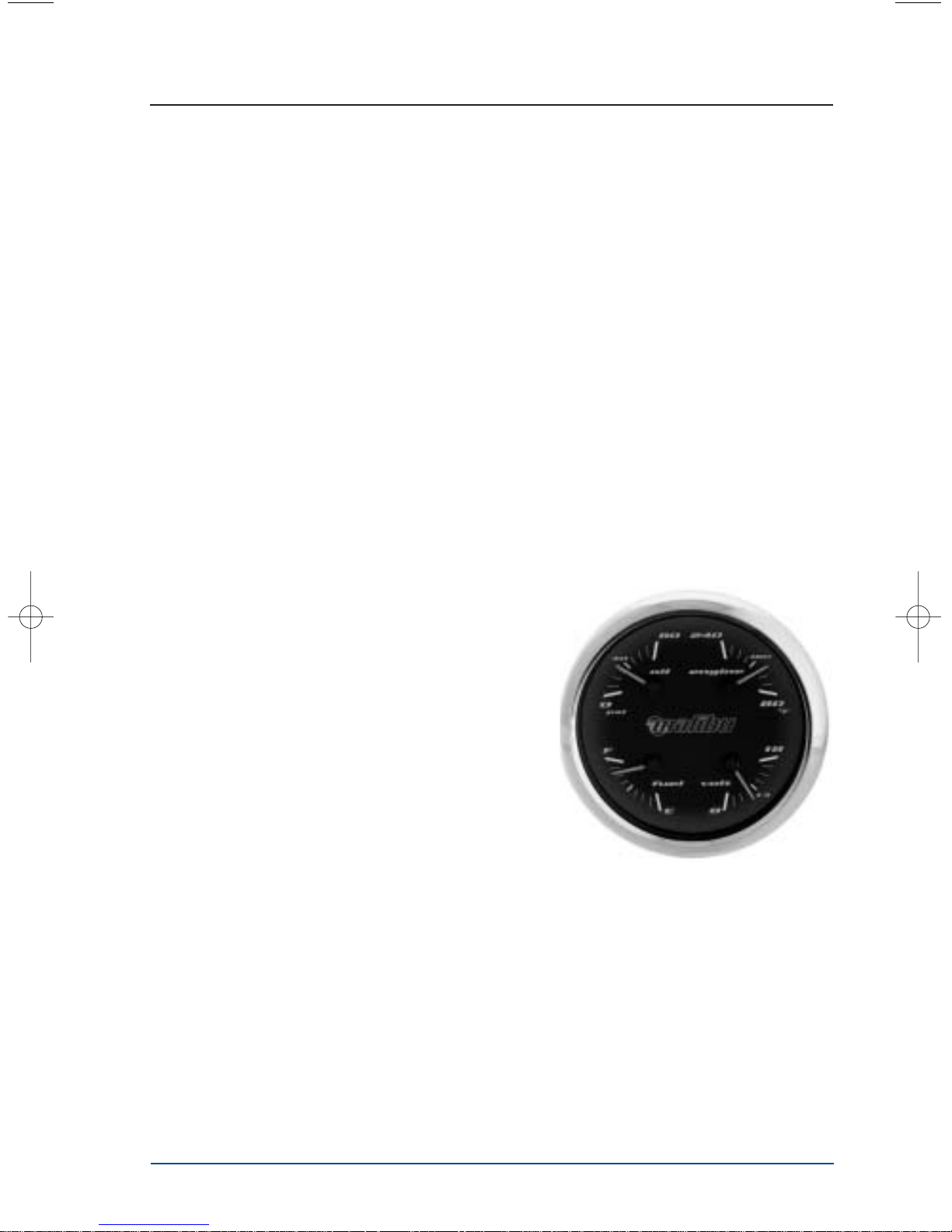
Multi Gauge
This single gauge combines the functions of four individual gauges for quick monitoring
at-a-glance.
●
Temperature Gauge
The Temperature Gauge indicates the
temperature of the water/coolant inside the
engine. The proper operating range for your
engine is between 140-160 degrees Fahrenheit.
Engines equipped with the optional Monsoon
engine have a control in the engine control
module that will cause the engine to run at
reduced speeds if the module senses that the
engine is running to hot. If you notice that your
speed has reduced during normal operation
without reducing the throttle, monitor your
temperature gauge. If your gauges indicate
excessive temperatures during operation, slow
down immediately and turn off engine.
Continuing to operate the boat while the temperature is above normal operating
parameters may cause serious damage to your engine.
●
Voltmeter Gauge
The voltmeter indicates whether the battery is charging or discharging. The needle
should be in the normal range (approximately 14 volts) while the engine is running.
Readings in either warning zone indicate a possible problem in the electrical system.
Figure 2-6. Multi Gauge

2-6
●
Fuel Gauge
The fuel gauge indicates the quantity of fuel remaining in the tank when the ignition
is in the “ON” position. Although your fuel tank will still have some fuel remaining
even though the gauge reads empty, it is recommended that the tank be filled when
the gauge indicates 1/4 full.
Do not top off tank!
Notice: It is not uncommon during the operation of your boat for
the fuel gauge to register slightly different amounts than
what is actually in the tank. This is normal operation and
does not indicate a problem.
For more information on fueling your boat, see “Fueling” under the “Operation”
section of this manual.
●
Oil Pressure Gauge
The oil pressure gauge indicates the oil pressure in the engine while the engine is
running and is measured in pounds per square inch (PSI). Oil pressure may vary with
engine speed, outside temperatures, oil viscosity, and other environmental factors, but
readings above the low pressure zone indicate the normal operating range. If the oil
pressure reading is below the normal range, you should stop the engine immediately
and check your oil as soon as possible.
Average pressure ranges are between 6 PSI at 1000 RPM and 40 PSI at cruising
speeds. If you are experiencing low oil pressure, stop your engine immediately and
check your oil level before operating again.
Do not continue to run engine if pressure is low. If you do,
the engine can become so hot that it or surrounding
components could catch on fire.
Notice: Damage caused from neglected oil problems can be
costly. Such damage is not covered by your warranty.
 Loading...