

Malibu Boats MHYA-DG Instructions Manual

Item No: MHYA-DG
HYANNIS DOUBLE GLIDER
Assembly Instructions
Hardware and Parts
I
(Left Arm Leg
Assembly)
(Glider Right Base Assembly)
L
M
N
I
( Seat Bottom )
Assembly
(Glider Right Base Assembly)
J
(Glider Left Base
Assembly)
L
(Glider Base Mid Brace 1 & 2)
K
M
N
( Seat Back Assembly )
H
Assembly Instructions
Figure 1
( Seat Bottom )
Assembly
I
( Seat Back)
Assembly
H
C
( Detail 1 )
O
( Back Alum. cover )
1A - Attach part ( H ) ,
Seat Back Assembly
, to part ( I ),
Seat Bottom Assembly
, as shown in Figure 1,
see detail 1 using ( 5 ) of screw ( C ) , 2 on each side,
tighten screws using an Allen Wrench .
1B - Attach part ( O ) ,
Back Alum cover
, to Assembly from
figure 1, as shown in detail 1a , using ( 4 ) of screw ( G ),
and tighten screws using a phillips-head screwdriver.
G
C
(4)
2.75
2.50
B
(15)
(Right Arm Leg )
Assembly
A
(6)
3.50
G (4)
C
1.50
(6)
F1
(6)
(4)
D1
E2
(8)
D2
(6)
E1
F2
(4)
Please contact one of our Product Specialists for assembly assistance or questions at 1-866-947-7632 or email info@malibu-outdoor.com.
Specialists are available weekdays 8:30 a.m. to 4:30 p.m. EST
CARE AND MAINTENANCE
To clean Your product, use mild soap and water. For heavy soil build-ups use any Non-Abrasive household cleaners.
2 - Attach parts ( M ) ,
Glider Base Mid Brace 1 & 2
, to
parts ( L ),
Glider Right Base Assembly and part ( N),
Glider Left Base Assembly
, as show in Figure 2
see detail 2 using ( 8 ) of screw ( C ), 4 on each side
and tighten screws using an Allen Wrench .
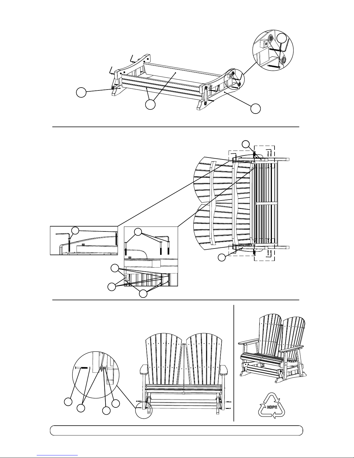
Figure 2
C
(Glider Base Mid Brace 1 & 2)
M
(Glider Left Base Assembly)
N
(Glider Right Base Assembly)
L
( Detail 2 )
Figure 3
3 - Attach part ( J ),
Right Arm Leg Assembly
, and part ( K ) ,
Left Arm Leg Assembly
, to Assembly from Figure 1 as shown
in Figure 3 see detail 3 and detail 4 .
Detail 4 - using ( 2 ) of screw ( C ) *,
and tighten screws using an Allen Wrench .
*( apply same step for other side )
Detail 3 - using ( 3 ) of joint connector bolts ( A ) ,
( 3 ) washers ( D ), ( 3 ) Lock washers ( E) and ( 3 )
hex nuts ( F )*, tighten bolts using an Allen Wrench .
*( apply same step for other side )
(Right Arm Leg Assembly)
J
( Detail 3 )
( Detail 4 )
C
A
D
E
F
Figure 4
4 - Attach the
Assembly from figure
3, ( Glider Seat ) to Assembly
from Figure 2, ( Glider Base ) as shown in Figure 4
See detail 5
using for each leg ( 1 ) of joint connector bolts ( B ) , ( 2 ) washers ( D ),
( 1 ) Lock washers ( E ) and ( 1 ) hex nuts ( F ),
tighten bolts using an Allen Wrench .
B
D
E
F
( Detail 5 )
(Left Arm Leg Assembly)
K
J
 Loading...