

Page 1

©
Malem© Universal
Wireless Alarm Model MO15
IMPORTANT
Please read instruction booklet
before use
Instructions for use
The alarm can be used for several applications
or combinations:
l
Wander alarm
l
Sit up alarm
l
Sleepwalking alarm lDialysis leakage alarm
Up to seven clients can be monitored with one receiver
Ideal for nursing/care homes, special schools, hospitals,
institutions and individuals
Helps to prevent bed sores and broken bones in
Dementia, Alzheimer’s, Memory Loss, the Elderly,
People with Special Needs
l
Continence alarm
l
Enuresis alarm
Page 2

Disclaimer
Malem© Universal©Wireless Alarm is designed
as a helpful and versatile aid. It is not intended
to replace human care or supervision and
the manufacturer, Malem Medical,
is not responsible for any consequences
resulting from the use,
misuse or failure of this device.
Page 3

Contents
Instructions for Use
Easy-Clip©Sensor........................................................................2
Standard Sensor ..........................................................................3
Bed-Mat ......................................................................................4
Wander-Mat..................................................................................6
Dialysis-Mat ................................................................................7
Resetting Receiver (Rx) Sound ....................................................7
Channel Selection ........................................................................8
Receiver LED Number Selection..................................................8
Re-tuning (Pairing)........................................................................8
Sound Selection Switch ..............................................................8
Batteries ......................................................................................9
Guarantee ....................................................................................9
Repairs ........................................................................................9
Cleaning........................................................................................10
Disposal........................................................................................10
Fault Finding ................................................................................10
Specification Tx & Rx ..................................................................11-12
Diagrams Tx & Rx ........................................................................13-16
How to Connect Tx with Different Sensors..................................17-19
The Inverter ..................................................................................20-21
MM100111
Page 4
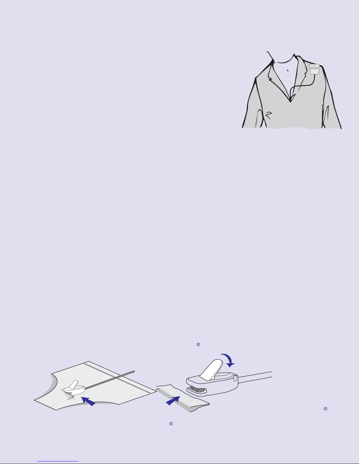
Instructions for use
Lock the Easy-Clip
onto the material by
pressing down the lever
IMPORTANT:
Regularly CLEAN Easy-Clip
Sensor in soapy water, rinse
and shake dry
IMPORTANT: DO NOT PLACE
ANY MATERIAL UNDER THE
SECURING LEVER
Place underwear material into mouth
(jaws) at the front of the Easy-Clip
1. Switch on the receiver (Rx) unit. Green LED
will flash once every two seconds. See page 15.
2. Remove insulator from battery compartment
(if present) of the transmitter (Tx) unit. See page 14.
3. Plug the sensor of choice into the transmitter
(Tx) unit. See pages 17 & 18.
MALEM
UNIVERSAL
WIRELESS ALARM
TRANSMITTER
MO15(Tx)
©
4. If used with Easy-Clip
i) Make sure the Easy-Clip©Sensor lever is in the up position.
(Lowering the lever without placing material between the front jaws
will activate the transmitter and trigger the receiver buzzer). If buzzer
does not sound, retune Tx & Rx as per instructions. See page 8.
ii) Using the safety pin, attach the Tx to the pyjama top or nightdress
close to the shoulder. Attach Tx to material before wearing garment
if preferable. Carefully lock the safety pin. Do not use safety pin if
faulty. Optional shoulder clip is available for clinics on request if
safety pin use is unsuitable.
iii) Thread sensor lead inside top as shown in diagram above.
For small children, loop and tie sensor lead to shorten length.
iv) Attach sensor clip to the outside of close fitting underwear (at the
location where it is most likely to get wet first), by inserting the
folded underpants material inside the front jaw of the clip then
lowering the lever. (Lowering the lever without any dry material in the
©
Sensor (EC):
jaws will activate the Tx, trigger the Rx alarm and prevent the Rx
from being reset). Lift the lever and press the reset button. Do not
reset the Rx by switching off. Always use the reset button.
2
Page 5
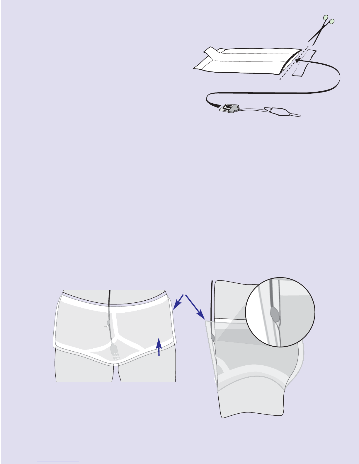
5. If used with Standard Sensor (BT):
a) Absorbent pad:
i) Cut off one end of an
absorbent pad such as sanitary
or incontinence pad and insert
the sensor in between the
layers.
ii) Anchor with crocodile clip
to prevent sensor from
being pulled out. Uncover
the backing strip and stick
the pad inside a pair of close fitting
pants, ensuring the sensor is located
where it will come into contact with the
flow of urine.
b) Between two pairs of underpants:
i) Sandwich between two pairs of cotton briefs (not boxer shorts).
Anchor with crocodile clip.
c) Within Y-front fold:
i) Place sensor plate within Y-fronts fold and anchor by locating the
crocodile clip on the outside of the waistband of the pants. Avoid
nylon/polyester underwear.
d) With pull-ups or nappies:
i) Cut a small slit into the outside of the material and insert the sensor
plate at a location close to the urine flow.
Outer Pants
Please note that sensor and clip
are gold plated
Please make sure the sensor plate and
the crocodile clip are attached between
the two pairs of pants and MUST NOT
come in contact with the skin
Inner Pant
3
Page 6

6. If used with Bed-Mat Sensor (BM):
a) Under no circumstances should the transmitter (Tx) be
attached to the users’ clothing when using a Bed-Mat.
b) Place a clean and dry Bed-Mat correct side up over the mattress
in the area which is normally wetted and gently tie down. See page 5.
c) Cover the Bed-Mat with a Clean Dry Cotton sheet and/or
Bath Towel and make the bed up as usual. Avoid
nylon/polyester sheets as they can cause ‘false’ alarms due to
increased perspiration. Adjust cover thickness over the mat to
suit.
d) Do not place plastic sheets directly under the Bed-Mat as
condensation will cause the alarm to trigger. (See diagram page 5)
e) Attach the Bed-Mat wire to the Tx and place the Tx beside the
bed. See page 17.
f) Please tuck in the Bed-Mat wire so that it is not in the way for
getting in and out of bed.
g) Upon waking to the Rx, try to stop any more urine from
being released and use the lavatory to completely empty the
bladder.
h) The Rx alarm sound can be stopped ONLY when the Bed-Mat
wire is unlocked from the Tx and the reset button on the Rx
is pressed.
i) For reuse, the Bed-Mat must be wiped clean with detergent and dried
then replaced in a freshly made bed, as before.
j) To test the system, place a damp cloth across the foil tracks on
the Bed-Mat.
4
Page 7
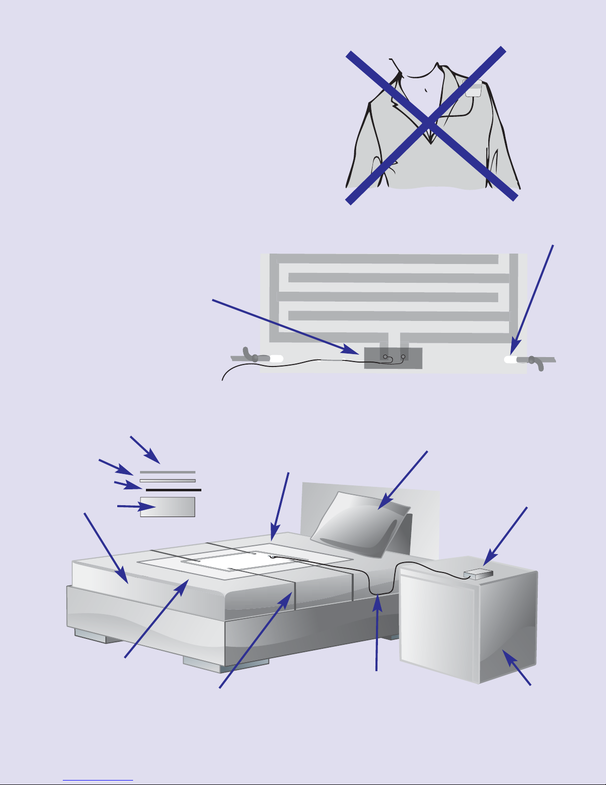
Under NO
circumstances should
the transmitter (Tx) be
attached to the users’
clothing when using a
Bed-Mat.
Holes for tying Bed-Mat to the mattress.
If using a plastic
protective mattress
sheet place adhesive
tape over the Bed-Mat
lower contacts.
MALEM
UNIVERSAL
WIRELESS ALARM
TRANSMITTER
MO15(Tx)
©
Bath Towel
Sheet
Bed-Mat
Mattress
Place cotton
sheet over
Bed-Mat.
Use a BATH TOWEL to
cover the Bed-Mat and
cotton sheet. Adjust towel
thickness to suit.
Tie Bed-Mat
around mattress.
Pillow
Transmitter (Tx)
Tuck wire from Bed-Mat to
alarm away neatly to prevent
tripping or entanglement.
Bedside
table
5
Page 8

Hints regarding the use of Bed-Mat:
l
l
l
l
l
l
l
l
Press the reset button once, receiver alarm sound will stop. LED will continue
to flash. If the Bed-Mat is not dried or disconnected, the alarm sound will start
again within two minutes.
Press and hold the reset button for two seconds to stop the alarm and turn off
the LED.
The Bed-Mat positively locks to the Tx to prevent accidental disconnection.
However, it must be unlocked before attempting to reset the alarm.
Please use a thicker cotton sheet or place a bath towel above
the Bed-Mat if sweating is triggering the Tx prematurely. Avoid plastic and
man-made fibres as they may cause static discharge and false alarm.
Treat the Bed-Mat with care. Avoid folding it or jumping on it.
Please replace the Bed-Mat with a new one if it has deteriorated and use a
new one with each user. (National Guidelines)
Please note that sleeping directly on an uncovered Bed-Mat or touching it by
hand may trigger the Tx and sound the alarm.
Do not place plastic sheets directly under the Bed-Mat as condensation may
trigger the alarm.
7.
If used with Wander-Mat Sensor (WM):
a) Activation by applied pressure: place the Wander-Mat (WM) in the
appropriate position depending on the way you wish to use it. The
Wander-Mat can be placed beside the bed or near the door so that
treading on the Mat will activate the Tx. Please place a door mat over
the Wander-Mat so as not to trip over the Wander-Mat. Plug into the
Tx and place away safely. See page 19.
b) Activation by removal of pressure: place the Wander-Mat (WM) over
the mattress but under the sheet, in a position so that the user is laying
over it or place on a chair so that the user is sitting on it. Plug the
Wander-Mat wire into the ‘inverter’ then plug the inverter wire into the
Tx and place Tx away safely. If the user gets out of bed or out of the
chair, the Tx will be activated triggering the Rx sound and selected LED.
c) Once the receiver (Rx) is triggered, the appropriate red LED will be
flashing. The buzzer sound can be silenced by pressing the reset button
on the top of the Rx. (Do not use the on/off switch to reset the Rx as
this will damage the microprocessor). The activated LED will remain
flashing. If the matched Tx remains active, the Rx will sound again after
two minutes. Press and hold for 3 seconds to deactivate and switch
LED off.
6
Page 9

8. If used with Dialysis-Mat Sensor (DM):
a) Select the correct side of the Mat with shiny tracks up.
b) Place the Mat over the chair arm.
c) Plug the Mat wire into the Transmitter, tuck the wire and place Tx out
of the way in a safe place. See page 18.
d) Test the Mat by placing a slightly wet tissue over the tracks. The Rx
should sound.
e) If sweating is likely to activate Tx and sound the alarm cover the Mat
surface with tissue paper. Adjust thickness to suit.
f) Rest patients arm over the Mat.
g) Wipe Mat clean and dry before use again.
9. Deactivating the Transmitter:
©
a) If using the Easy-Clip
sensor, lift the sensor lever and remove from
underpants (wash Easy-Clip©sensor frequently).
b) If using the Standard sensor, unclip the crocodile clip and remove the
sensor, wipe sensor plate dry and clean regularly.
c) If using the Bed-Mat, unplug the Bed-Mat from the Tx, remove the
sheet, wipe clean and dry thoroughly before repositioning.
d) If using the pressure/release Wander-Mat, unplug from the Tx and
reposition the user on the Mat.
c) If using the Dialysis-Mat, unplug from the Tx, clean and dry the Mat
then, reposition.
f) Press the reset button on the Rx to silence the buzzer.
10. Resetting the Rx Sound:
a) Press and hold the reset button for 2 seconds to switch off the
sound and de-activated LED/s (make sure matched Tx is not active).
b) The matched Tx/Rx will not trigger the Rx if the Tx is activated within
2 minutes of previous activation.
c) For easy identification, an adhesive label can be used on the front of
the Rx where you can write the room number or occupant name for
each of the seven LEDs.
7
Page 10

Channel Selection see diagram on page 14
ON
1 2 3 4 5 6
OFF
ON
1 2 3 4 5 6 7 8
OFF
The Malem Universal©Wireless Alarm consists of a receiver which
can be paired with up to seven transmitters. To avoid interference
from the 7 transmitters or other wireless equipment, you need to
select different channel settings for each of the transmitters. A choice of 64
settings is possible and should be changed in case of interference.
To change the channel setting, remove the back of the transmitter using a slotted
screwdriver. Lower to open. Change the setting of the code selection switch (the
one on the left) by moving any of the switches in any of the 64 combinations.
Receiver LED Number Selection see diagram on page 14
To match a Tx with a specific Rx LED number, remove the battery cover of the
Tx using a slotted screwdriver. The LED selection switch is the one on the right.
Select the LED number by sliding the matching number (between 1 and 7) of the
sliding switch to ON. Re-tune Tx and Rx. See below.
Re-tuning the Rx and Tx see diagram on page 14 & 16
All additional transmitters will need to be re-tuned with the Rx.
a) Select the desired Rx LED number first (see above).
b) Push and release the straight end of a paper clip into the small
LEFT hole at the back of the receiver. All the 7 LED’s will glow.
c) Immediately and while the LED’s are glowing, activate the Tx you wish to
©
tune/re-tune by lowering the Easy-Clip
sensor lever or wetting the
standard sensor or Bed-Mat or applying pressure on the Wander-Mat or
wetting the Dialysis-Mat.
d) The LED’s will switch off apart from the selected one which will glow on
and off. The next activation of the Tx will activate the Rx LED and the buzzer.
e) Repeat for all other additional transmitters.
f) Remember to change channel if you are experiencing any interference
from other transmitters or wireless equipment.
You can also tune several receivers to the same transmitters. This is helpful if
more than one carer wants to monitor the transmitters.
Sound Selection Switch see diagram on page 16
The receiver is factory set to 8 random sounds.
For single sound selection:
a) Open the Rx battery cover using a slotted screwdriver. Insert blade into
slot and twist.
b) Slide to ‘ON’ any one of the switches between 1 and 8.
c) Slide all other switches apart from 10 to the ‘OFF’ position.
d) Do not slide switch 10 to ‘OFF’ as this will silence the Rx sound.
8
Page 11

Important
l
l
l
l
l
l
l
l
Remove batteries from both Tx and Rx if not in use.
Observe clean battery compartment contacts and correct polarity when
changing batteries.
Use long life alkaline batteries whenever possible.
Batteries should not be accessed by children and only replaced by adults.
Do not immerse the Tx or Rx in water.
Regularly clean the sensor in use. See page 10.
Do not leave the Tx active (LED on) as this will drain the battery. See page 13.
Do not use the receiver ‘ON/OFF’ sliding switch as a reset button as this
will damage the microprocessor. Always use the ‘Reset’ button.
Batteries (remove isolating tag if present)
Batteries have been provided free of charge with original purchase to enable
testing during manufacture and prior to packaging. Additional batteries can be
purchased. Batteries should not be accessed by children and only replaced by
adults. Use long life alkaline batteries whenever possible. Do not leave Tx active
when not in use as this will drain the battery. Observe correct polarity and clean
contacts when replacing Tx and Rx batteries.
Tx: alkaline 23A 12V
Rx: alkaline 3 x AA
Replace batteries on the Tx or Rx if the LEDs are rapidly flashing.
Safety pin
Pull white cover slightly to unlock, push to lock, you can replace the safety pin by
sliding the replacement bar to the left. See page 14.
Guarantee
Under normal usage, the Malem Universal©Wireless Alarm is guaranteed for a
period of three months from purchase. This excludes batteries, sensors, Bed-Mat,
Wander-Mat, Dialysis-Mat, safety pin, flooding, misuse or accidental damage. If
the alarm should malfunction during this period, please contact us before sending.
Please remove the batteries and decontaminate the unit/s sensor before returning.
Do not return flooded or contaminated alarms.
Repairs
If repairs are required, we will exchange for a new alarm (repairs are not untaken
for health and hygiene reasons). Please contact us by telephone, e-mail or in
writing for the cost of this service. Please decontaminate the units/s before return.
Do not return contaminated or flooded alarms.
9
Page 12

Cleaning
Alarm units (Tx and Rx):
Wipe clean alarm and safety pin using a damp cloth and mild detergent or skin
disinfectant. NEVER IMMERSE IN WATER
Sensors (wash regularly):
Easy-Clip©- lift lever, wash in warm soapy water, rinse under the tap
and shake dry.
Standard Sensor - wash in soapy water and dry thoroughly.
Bed-Mat - wash in warm soapy water and wipe dry.
Wander-Mat - wipe with damp cloth and mild detergent, dry thoroughly.
Dialysis-Mat - wipe with damp cloth and mild detergent, dry thoroughly.
National guidelines state one user per Sensor/Mat.
Disposal
At the end of the alarms working life, please dispose of the product at a special
local authority differentiated waste collection centre.
Fault Finding
Alarm does not sound:
a) Switch on receiver Rx. Green LED should flash.
b) Replace batteries with new alkaline ones (3 x AA). Observe correct polarity
orientation and make sure contacts inside the battery compartment are
clean and free of any deposits.
c) Sound selection switch has been wrongly set or switch No.10 has been
set to OFF. Reset all switches to their original position as per diagram on
page 16.
d) Remember that the Rx will not sound again within 2 minutes of being
activated by the Tx. However the Rx will be activated if other Tx is
activated. The 2 minute delay is to allow the triggered Tx to be reset. If the
Tx is not reset, then the Rx will sound again after 2 minutes if the reset
button has been pressed to silence the buzzer.
e) Does the Tx LED glow when the Tx is activated by lowering the lever on
©
the Easy-Clip
Mat/Dialysis-Mat or applying pressure on the Wander-Mat? If it does not
sensor or wetting the standard sensor or Bed-
glow, then replace the Tx battery (alkaline 23 A 12V). Observe correct
polarity and clean contacts.
f) Remove isolating tags from battery compartment in Tx and Rx. Retune Tx
and Rx. If all fails, return Tx and Rx for investigation. Contact us before
doing so. Decontaminate all units before returning. See diagram on pages 13
and 16.
10
Page 13

Alarm does not reset:
a) Clean Easy-Clip©sensor by lifting lever, wash in warm soapy water, rinse
under the tap and shake dry. Repeat if necessary.
©
b) Make sure Easy-Clip
sensor lever is NOT down without dry material
between the front jaws.
c) Clean Bed-Mat and dry thoroughly. Use thicker towel over Mat. Do not
use man made sheets over the Mat.
d) Clean Dialysis-Mat and dry thoroughly. Use thicker tissue paper or
material under the arm.
e) Remove pressure or apply pressure to Wander-Mat.
f) Make sure underpants material is not too thin or wet.
g) Replace Tx and/or Rx batteries.
h) Transmitter is damaged or flooded.
Sound level is too low:
a) Adjust sound level with volume control. See diagram on page 15.
LED flashing rapidly:
a) Replace battery.
Specifications MO15 Transmitter (Tx)
Colour: red
Weight: 33g including battery, 25g without battery
Dimensions: length: 50mm width: 45mm depth: 21mm
Range: approximately 25m depending on nature of the structure and the state
of the battery.
Battery cover: to remove, place a slotted screwdriver in the bottom slot and
lower the handle. Battery: alkaline 23 A. Observe correct polarity when replacing
and ensure no deposits are on the metal contacts.
Safety pin: pull white cover slightly to unlock, push to lock, you can replace the
safety pin by sliding the replacement bar to the left. Do not use faulty safety pin.
Red LED: flashes when transmitter is active. Do not leave on for extended
length of time as this will drain the battery. LED will flash rapidly for 3 minutes
and then turn off when battery capacity is low. Replace battery.
Frequency: 433 MHz
Model: MO15 Tx
Standards: and
11
Page 14

Specifications MO15 Receiver (Rx)
Colour: red
Weight: 136g including batteries, 67g without batteries
Dimensions: length: 91mm width: 72mm depth: 26mm
Battery: 3 x AA alkaline. Observe correct polarity and clean contacts when
replacing batteries.
ON/OFF: sliding switch on side
Volume: volume control wheel on the side. Turn up to increase and down to
decrease. Reset button on the top will not reset if Tx is active. Press button and
hold for 3 seconds to cancel active LED. Do not use ON/OFF button to reset the
receiver.
Green LED: flashes once every 2 seconds when Rx is ready for use. Red LED 1
to 7: ON when paired Tx is triggered. Up to 7 Txs can be tuned and paired to
the 7 LEDs. Once an LED is activated, even paired ON, when reset, it will not be
triggered again for 2 minutes. The LED and buzzer will be reactivated if the
linked Tx remains active.
Tuning point: 2 small pin holes on the back of the Rx. The one on the left is the
tuning hole. Insert the straight end of a paper clip into the hole and press
slightly then release, all the red LEDs will glow. While the red LEDs are on,
activate the Tx. The LEDs will go off and only the LED which has been selected
on the Tx will flash. When the Tx is activated again, the LED will flash and the
buzzer will sound. Green LED will flash rapidly when battery capacity is low.
Replace battery.
Default hole: the small hole on the right on the back of the Rx is the default
hole. Insert the straightened end of a paper clip and press gently then release.
This will erase all the tuned memory. Re-tuning to the Tx/s will be required.
Model: MO15 (Rx)
Standard: and
Sensors
Easy-Clip©: Length 79 cm. Keep lever up when not in use. Clean sensor regularly.
Standard: Length 79 cm. Keep clean and wipe dry. The sensor plate and
crocodile clip MUST NOT be in direct contact with the skin.
Bed-Mat: 54 x 42 cm. Wire length 202 cm. Keep clean and wipe dry. Always
cover with cotton sheet as well as a bath towel. Under no circumstances should
the transmitter (Tx) be attached to user’s clothing when used with a Bed-Mat.
Wander-Mat: 75 x 40 cm. Wire 150 cm. Use pressure on or pressure off (for
pressure off use with ‘inverter’).
Dialysis-Mat: 22 x 17 cm. Wire 100 cm. Keep clean and wipe dry.
Malem Medical reserves the right to change specifications without prior notice.
©2011 Malem Medical
12
Page 15
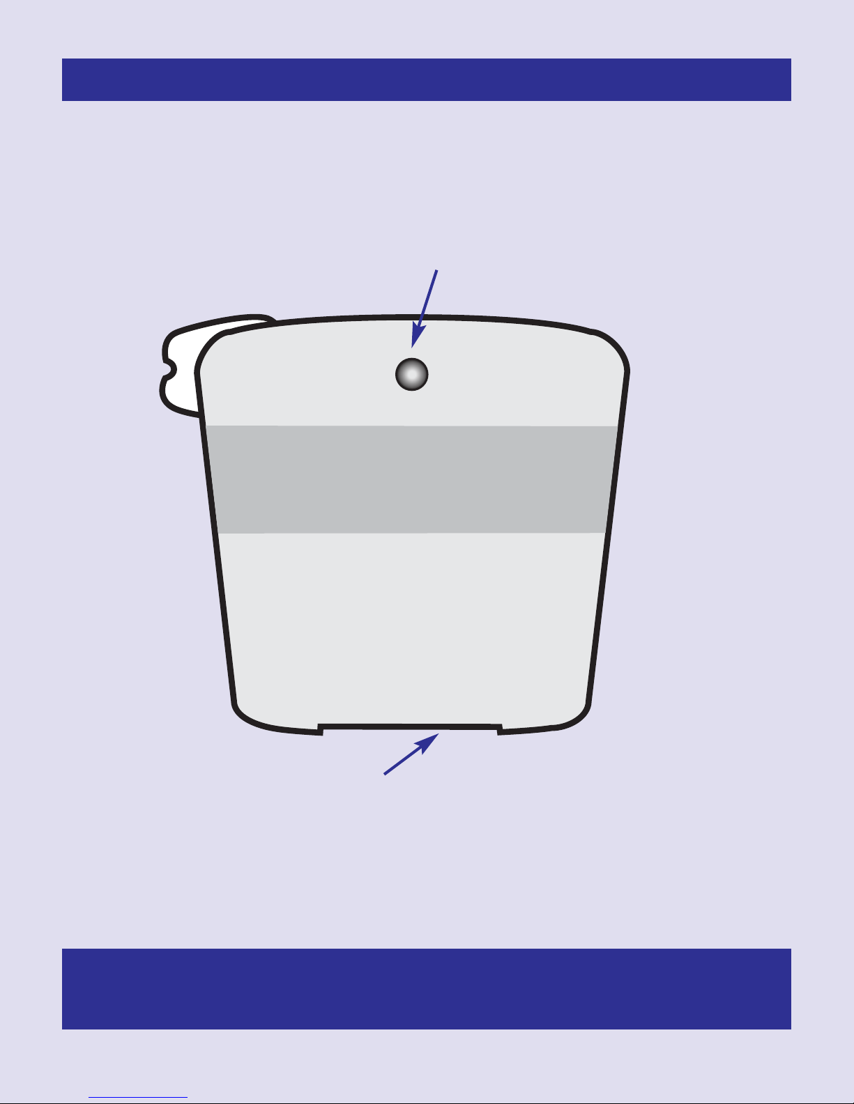
MALEM
©
UNIVERSAL
WIRELESS ALARM
TRANSMITTER
MO15 (Tx)
Malem©Universal©Wireless Alarm Transmitter
MODEL MO15 (Tx)
Red LED flashes when Tx is active. Please do not leave on as this will drain
the battery. If using the Easy-Clip©sensor, please make sure the lever is up
when not in use or unplug the sensor from the socket.
LED will flash rapidly for 3 minutes then turn off when the battery capacity
is low. Replace battery.
Use Alkaline batteries ONLY
Sensor locking socket
13
Page 16
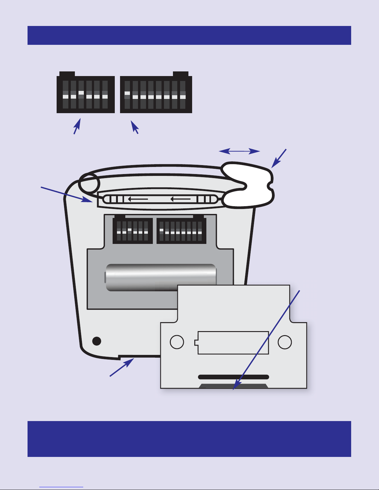
ON
1 2 3 4 5 6
ON
1 2 3 4 5 6 7 8
23A 12V ALKALINE
OPEN
+
-
ALKALINE
CHANNEL
SELECTION
SWITCH
Rx LED No.
SELECTION
SWITCH
OPEN
23A 12V
ALKALINE
+
-
MODEL
MO15(Tx)
Malem©Universal©Wireless Alarm Transmitter
ON
1 2 3 4 5 6
ON
1 2 3 4 5 6 7 8
OFF
OFF
MODEL MO15 (Tx)
Safety pin
slide cover
sideways
Channel selection
switch
Safety pin
replacement
bar
Receiver LED
selection switch
lock unlock
to lock or unlock
Battery
compartment
To open place
slotted
screwdriver in
slot and move
Sensor
locking
socket
handle down
Use 1 x 23A 12V
Alkaline batteries
Please observe
correct polarity
when replacing
batteries
Use Alkaline batteries ONLY
14
Page 17
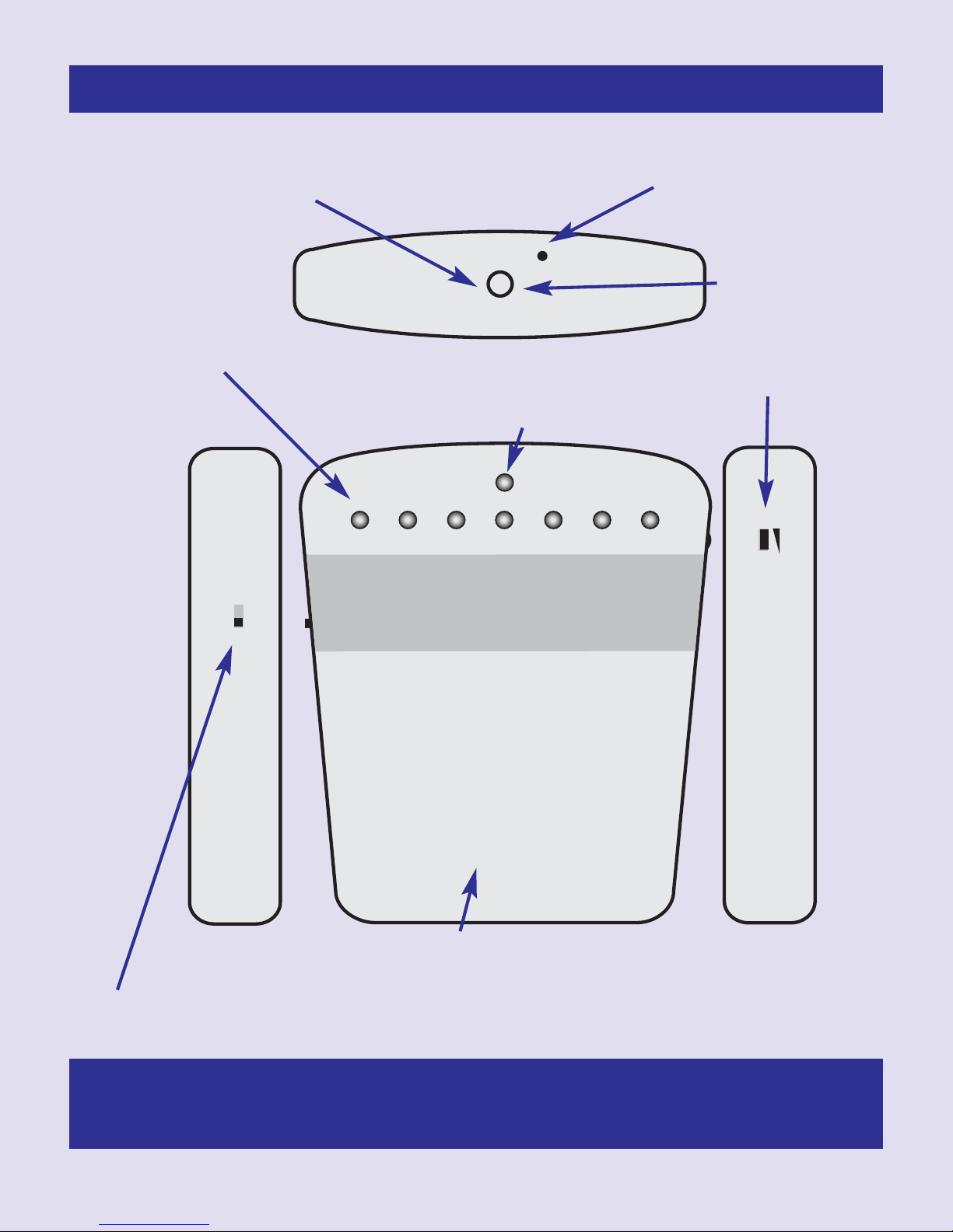
MALEM
©
STANDBY LED/2 SEC
1 2 3 4 5 6 7
UNIVERSAL
WIRELESS ALARM
RECEIVER (Rx)
OFF ON
POWER
- +
VOLUME
Malem©Universal©Wireless Alarm Receiver
MUTE / RESET BUZZER
PRESS & HOLD FOR 3 SEC TO RESET
MODEL MO15 (Rx)
Mute/reset
Red LEDs 1-7
Each light
corresponds to the
transmitter it is
paired with.
Green standby LED/2 sec flashes.
LED will flash rapidly when battery
capacity is low. (Replace battery)
Buzzer
Press and
hold for 3
sec to reset
Volume
Attach a label to the front of the Rx to indicate
Power OFF - ON. Please do not use on/off switch to reset alarm.
This will damage the microprocessor. Use reset button.
LED number, room number or users name.
Use Alkaline batteries ONLY
15
Page 18
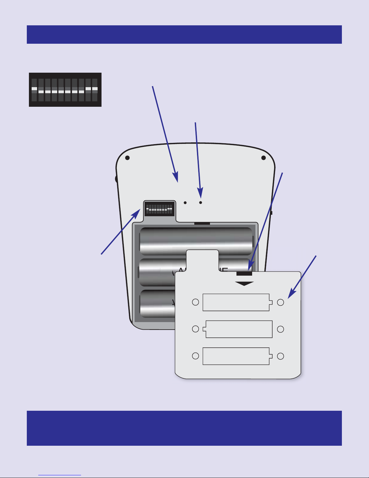
Tx Rx
PAIRING
DEFAULT
AA ALKALINE
AA ALKALINE
AA ALKALINE
USE 3 x AA
ALKALINE BATTERY
+
-
USE 3 x AA
ALKALINE BATTERY
+
-
USE 3 x AA
ALKALINE BATTERY
+
-
OPEN
SEE INSTRUCTIONS
FOR USE
SOUND
SELECTION
SWITCHES
ON
1 2 3 4 5 6 7 8 9 10
Malem©Universal©Wireless Alarm Receiver
ON
1 2 3 4 5 6 7 8 9 10
OFF
MODEL MO15 (Rx)
To reset and erase all pairing memory use
Tx Rx Pairing
Tx Rx Pairing.
Use end of paper
clip. Pass into hole,
press and release,
all red LEDs On,
activate required Tx
while red LEDs are
paper clip. Insert the end of a paper clip into
the hole. Only use default to erase all pairing
memory. Press and hold for 3 seconds. All
pairing with Tx will be lost.
To open battery
compartment
place slotted
screwdriver in the
slot then twist.
On, one of the LEDs
will flash the same
number as the
switch number
selected on Tx.
Sound selection
switch
Switch 1 - 8 will
select sounds 1 - 8.
Switch 9 must be
off for single sound.
For 8 sounds switch
1 as well as 9 and
10 must be On.
Sounds will be Off if
switch 10 is in the
Off position.
Batteries: 3 x AA
Please use
alkaline. Observe
correct polarity.
Make sure metal
contacts are
clean.
Use Alkaline batteries ONLY
16
Page 19
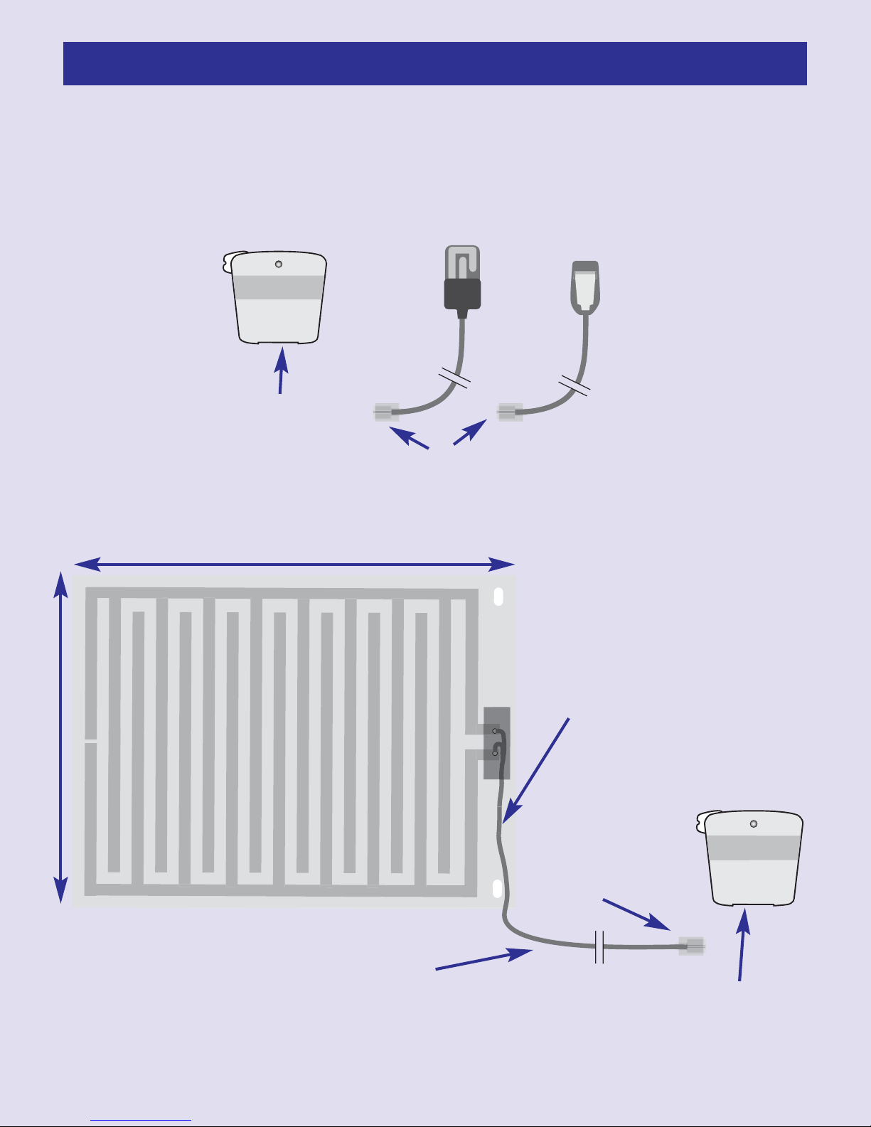
Activation of the Tx using different sensors
MALEM
©
UNIVERSAL
WIRELESS ALARM
TRANSMITTER
MO15 (Tx)
1. Activation by Easy-Clip©Sensor
or Standard Sensor
Malem Transmitter (Tx)
Standard Sensor (BT)
Plug sensor into Tx socket
RJ10 plug
2. Activation using a Bed-Mat:
54 cm
©
Easy-Clip
Sensor (EC)
Lever - Keep up when
not in use. Clean clip
regulary.
42 cm
Bed-Mat (BM)
Bed-Mat connection wire
202 cm
Malem Transmitter (Tx)
MALEM
RJ10 plug
Plug Bed-Mat RJ10 plug into the
Malem transmitter socket
17
UNIVERSAL
WIRELESS ALARM
TRANSMITTER
MO15 (Tx)
©
Page 20
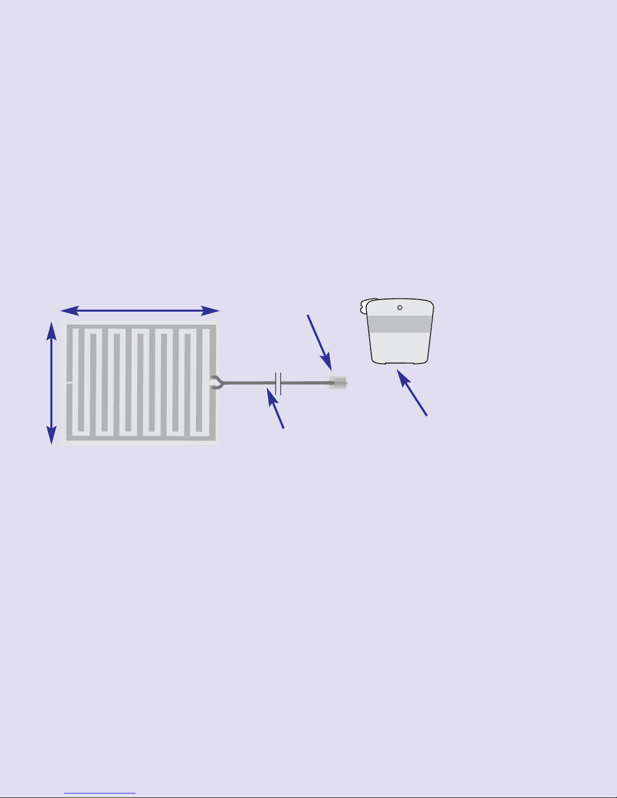
3. Activation using a Dialysis-Mat
MALEM
©
UNIVERSAL
WIRELESS ALARM
TRANSMITTER
MO15 (Tx)
Malem Transmitter (Tx)
17 cm
22 cm
Dialysis-Mat (DM)
RJ10 plug
Plug Dialysis Mat RJ10
DM connection wire
plug into the Malem
100 cm
transmitter socket
18
Page 21
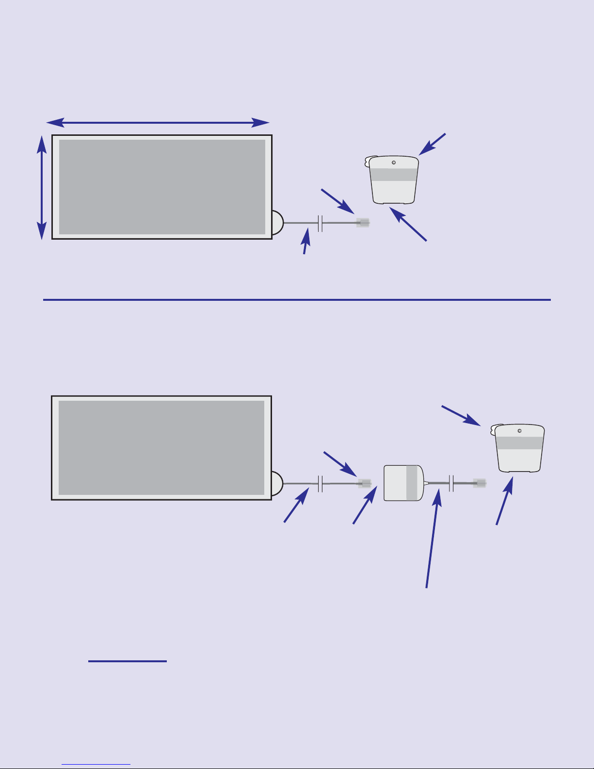
Wander-Mat with inverter
MALEM
©
UNIVERSAL
WIRELESS ALARM
TRANSMITTER
MO15 (Tx)
WANDER MAT
MALEM
©
UNIVERSAL
WIRELESS ALARM
TRANSMITTER
MO15 (Tx)
WANDER MAT
MALEM
©
PRESSURE
MAT
INVERTOR
4. Activation by applying pressure
75 cm
Malem Transmitter (Tx)
RJ10
plug
40 cm
Wander-Mat (WM)
WM connection wire
150 cm
5. Activation by removing pressure:
(user must be lying in bed or sitting over WM in a chair)
:
Plug WM
plug into Tx
socket
Malem Transmitter (Tx)
PM
Inverter
Plug inverter
plug into Tx
socket
Wander-Mat (WM)
RJ10
plug
WM
connection
wire
Plug WM
into inverter
socket
WM inverter wire
Please note that pressure must be applied to the
Mat BEFORE attempting to set up the connection.
19
Page 22
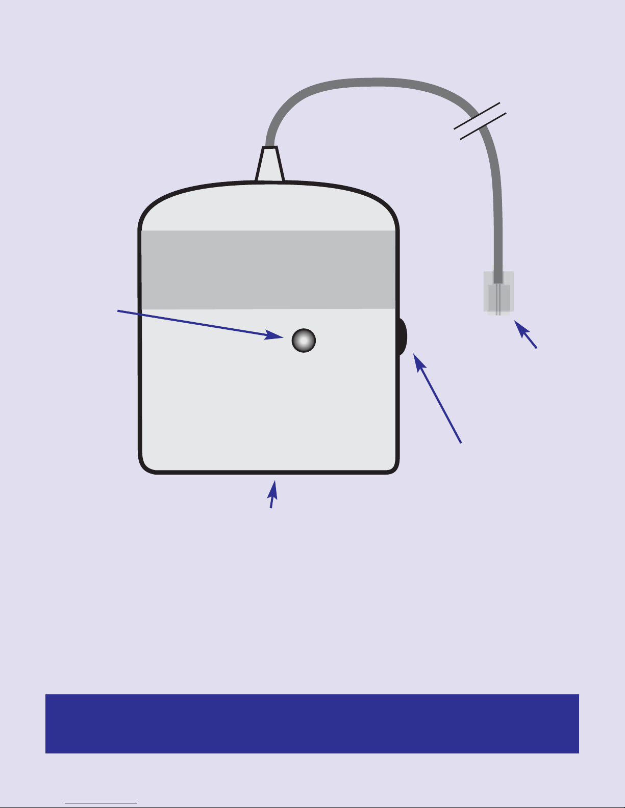
Malem Wander-Mat Inverter front:
MALEM
©
WANDER
MAT
INVERTOR
LED light
The RJ10
plugs into the
transmitter (Tx)
Battery test button
The RJ10 Wander-Mat (WM) plug, plugs into the inverter socket
Please plug in the inverter wire between the Wander-Mat and the transmitter.
Battery test: press the button, LED will glow. If LED does not glow then change
the battery. (Remove battery isolator if present)
The inverter should be used ONLY if you wish to use the Wander-Mat to detect
removal of pressure.
Please do not immerse inverter or Mat in water.
Use Alkaline batteries ONLY
20
Page 23
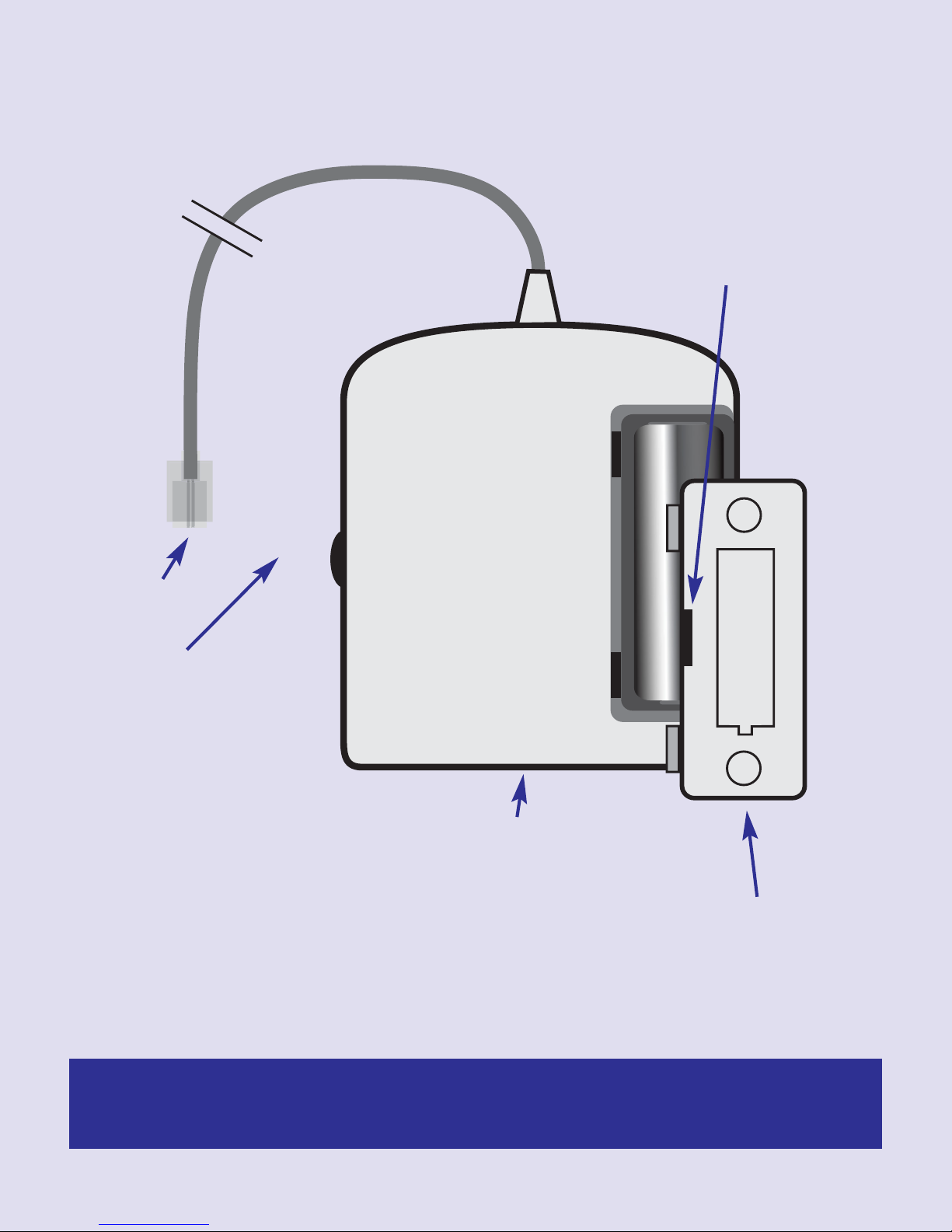
Malem Wander-Mat Invertor back:
23A 12V
ALKALINE
+
-
Use slotted
screwdriver to open.
Place tip in slot and
twist.
RJ10 plug
Battery test button
RJ10 socket
Please observe correct polarity. Contacts clean and battery not loose inside
compartment. Pull metal contact to make good connection. Use only 23A
12V Alkaline battery.
Use Alkaline batteries ONLY
21
Page 24

FCC ID: U9FMO15
This device complies with part 15 of the FCC
Rules. Operation is subject to the following two
conditions: (1) this device may not cause harmful
interference, and (2) this device must accept any
interference received, including interference that
may cause undesired operation.
NOTE:
Changes or Modifications not expressly approved by the party responsible could void the
user’s authority to operate this device.
NOTE: This equipment has been tested and found to comply with the limits for a Class B
digital device, pursuant to Part 15 of the FCC Rules. These limits are designed to provide
reasonable protection against harmful interference in a residential installation. This equipment
generates, uses and can radiate radio frequency energy and, if not installed and used in
accordance with the instructions, may cause harmful interference to radio communications.
However, there is no guarantee that interference will not occur in a particular installation.
If this equipment does cause harmful interference to radio or television reception, which can
be determined by turning the equipment off and on, the user is encouraged to try to correct
the interference by one or more of the following measures:
-- Reorient or relocate the receiving antenna.
-- Increase the separation between the equipment and receiver.
-- Connect the equipment into an outlet on a circuit different from that to which the
receiver is connected.
-- Consult the dealer or an experienced radio/TV technician for help.
Malem Medical, 10 Willow Holt, Lowdham
Nottingham NG14 7EJ, England, UK
Tel: + 44 (0)115 966 4440 Fax: + 44 (0)115 966 4672
E-mail: [email protected]
Web: www.malem.co.uk Web: www.malemmedical.co.uk
© Malem Medical 2011
 Loading...