

Page 1

VARIGATE 4 MANUAL V.1
VARIGATE 4
TEMPO COARSE
CLK IN
TEMPO FINE
RESET
PROB
REPEAT
DELAY
A B C D
GLOBAL
CLK DIVIDE
PULSEWIDTH
A LENGTH
B LENGTH
C LENGTH
D LENGTH
Page 2

VARIGATE 4 MANUAL V.1
TABLE OF CONTENTS
SPECIFICATIONS 1
INSTALLATION 2
DESCRIPTION 3
QUICK OVERVIEW 4
INPUTS AND OUTPUTS 5
PER-STEP PARAMETERS 6
RANDOMIZER 7
GLOBAL MODE 8
SAVING PRESETS 9
WARRANTY 10
MALEKKOHEAVYINDUSTRY.COM
Page 3

VARIGATE 4 MANUAL V.1
SPECIFICATIONS
FORMAT:
EURORACK
DIMENSIONS:
10HP, 23mm deep
INTERNAL AND EXTERNAL SIGNALS (3.5mm jacks):
0-5V Logic I/O
MAX CURRENT:
+12V: 50mA
-12V: 10mA
+5V: n/a
MALEKKOHEAVYINDUSTRY.COM
Page 4
VARIGATE 4 MANUAL V.1
INSTALLATION
Remove module from packaging.
Power down your modular synthesizer and disconnect the power cable from the
wall outlet.
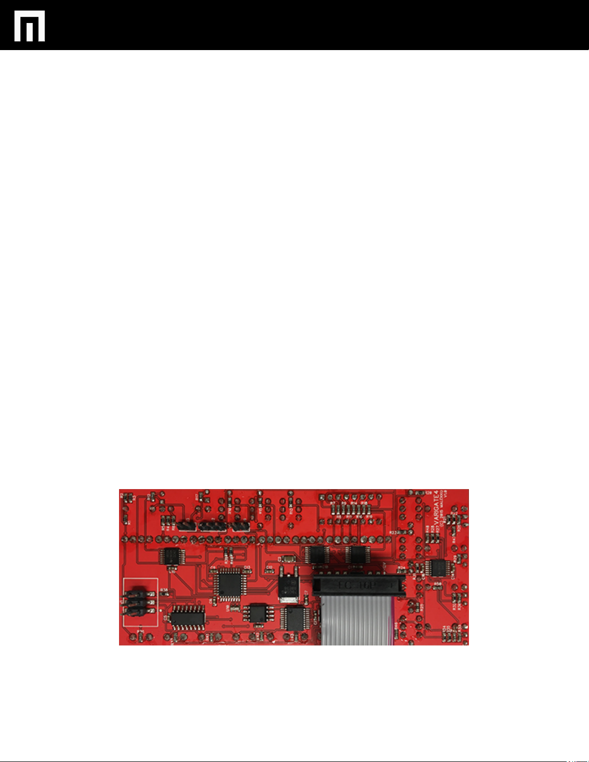
Attach the included power cable to the module’s power connector and connect the
other end to the power distribution bus in your EuroRack synthesizer case. If you
have a bi-colored ribbon cable the red stripe should be on a same side with a bold
white line on a pcb. In case if you have a rainbow-colored ribbon cable the key is
brown. Connector also has a key which should match sikscreen on a pcb.
Position the module on the mounting rails in your EuroRack case and screw down
mounting screws. Power up! If your case does not turn on properly then you have
installed the module incorrectly. Simply power down and make sure to follow the
diagram when reconnecting the module.
MALEKKOHEAVYINDUSTRY.COM
Page 5

VARIGATE 4 MANUAL V.1
DESCRIPTION
The Varigate 4 is a 4-channel, 8-step gate sequencer with parameter per-step control
of PROBABILITY, REPEAT AND DELAY as well as GLOBAL parameter controls.
CLOCK INPUT allows for external clocking to progress sequences and RESET gate
input sets all steps to 1. Varigate 4 also includes RANDOMIZER functions for both
REPEAT and DELAY. The additional ability to save presets make this compact
module perfect for live performance.
MALEKKOHEAVYINDUSTRY.COM
Page 6
VARIGATE 4 MANUAL V.1
QUICK OVERVIEW
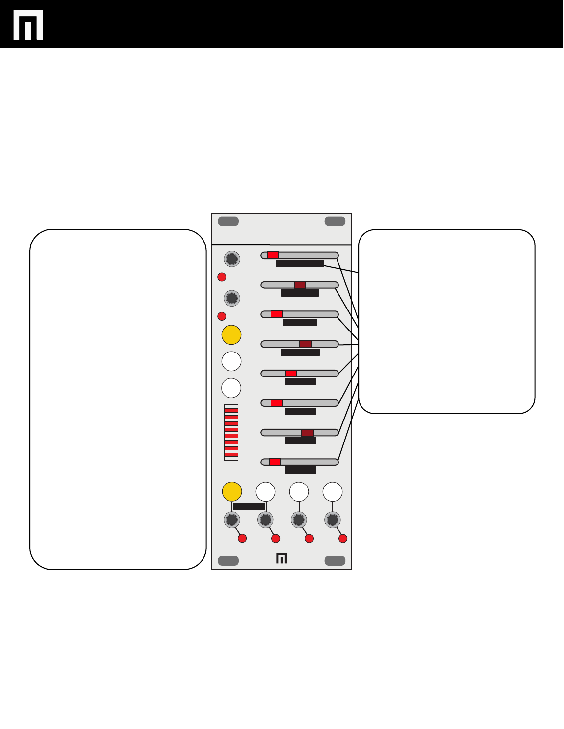
CLK IN: CLOCK INPUT with LED
indicator
RESET: gate input for resetting to step 1
and LED indicator
PROB: select to control the probablity of a
step outputting a gate.
REPEAT: select to control the amount a
step repeats
DELAY: select to control the amount of
delay per step.
LED BAR GRAPH: displays the step
currently being adjusted as well as a final
overview of all adjusted steps.
A, B, C and D selectors: select the
channel you want to adjust steps for
(orange indicates the channel selected)
Red LEDs for A,B,C and D indicate gate
outs for each channel.
VARIGATE 4
TEMPO COARSE
CLK IN
TEMPO FINE
RESET
PROB
REPEAT
DELAY
A B C D
GLOBAL
CLK DIVIDE
PULSEWIDTH
A LENGTH
B LENGTH
C LENGTH
D LENGTH
There are 2 modes, REGULAR and
GLOBAL. GLOBAL menu items are
outlined in black (see Diagram 5 for
more details on GLOBAL MODE).
Steps 1-8: Each step has it’s own
adjustable slider with an LED indicator that will flash. The sequence
moves from top to bottom.
MALEKKOHEAVYINDUSTRY.COM
Page 7
VARIGATE 4 MANUAL V.1
INPUTS AND OUTPUTS
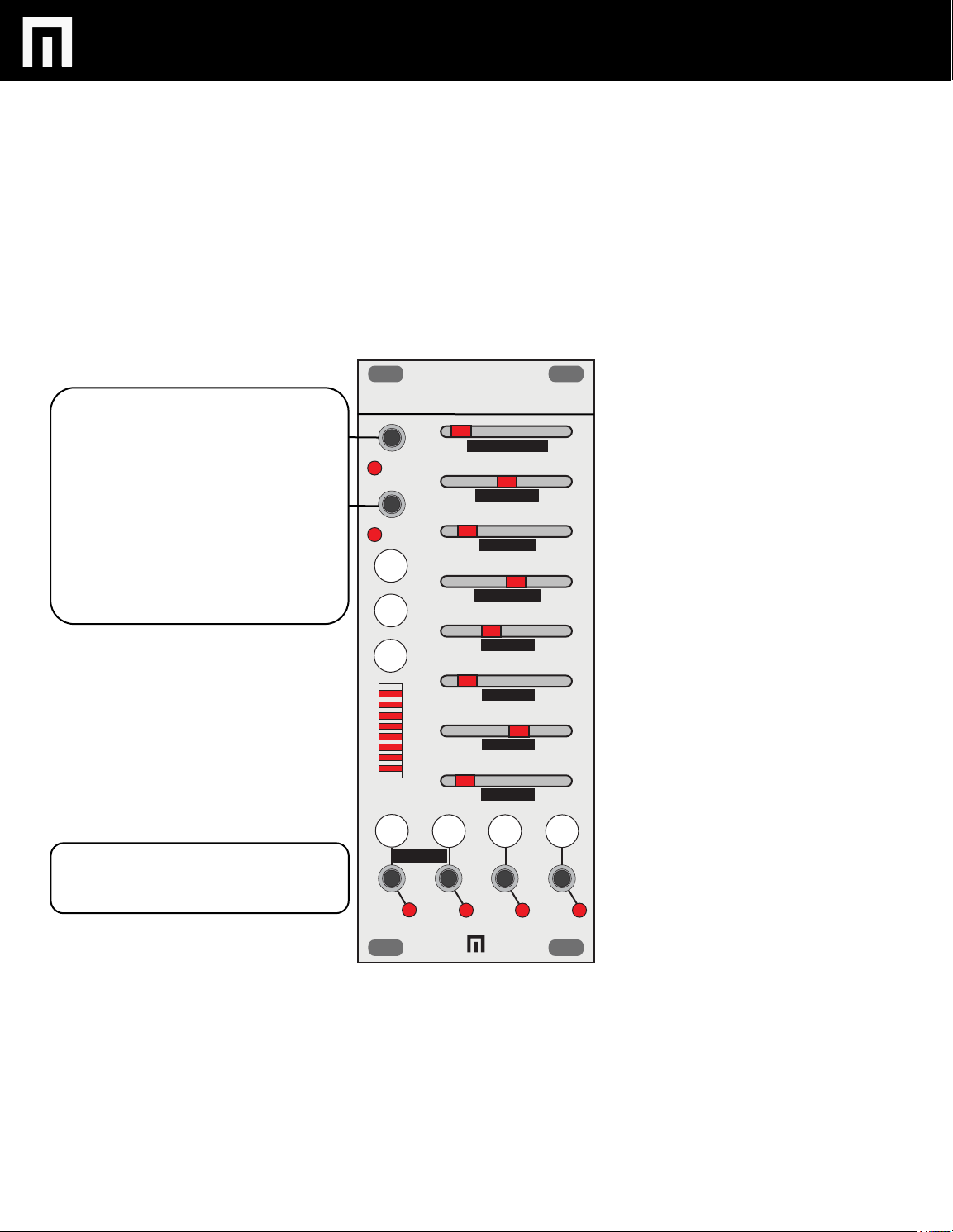
CLOCK INPUT - The sequence is
progressed with this input. With
nothing plugged in the clock can be
normalled to the module’s internal
clock or gate bus from the busboard
(set by jumper on back of module).
RESET INPUT - This gate input will
set all channels to step 1.
CLK IN
RESET
VARIGATE 4
TEMPO COARSE
TEMPO FINE
CLK DIVIDE
PROB
PULSEWIDTH
REPEAT
Channels A-D outputs - Each channel
outputs 5V gates.
DELAY
A B C D
GLOBAL
A LENGTH
B LENGTH
C LENGTH
D LENGTH
MALEKKOHEAVYINDUSTRY.COM
Page 8
VARIGATE 4 MANUAL V.1
PER-STEP PARAMETERS
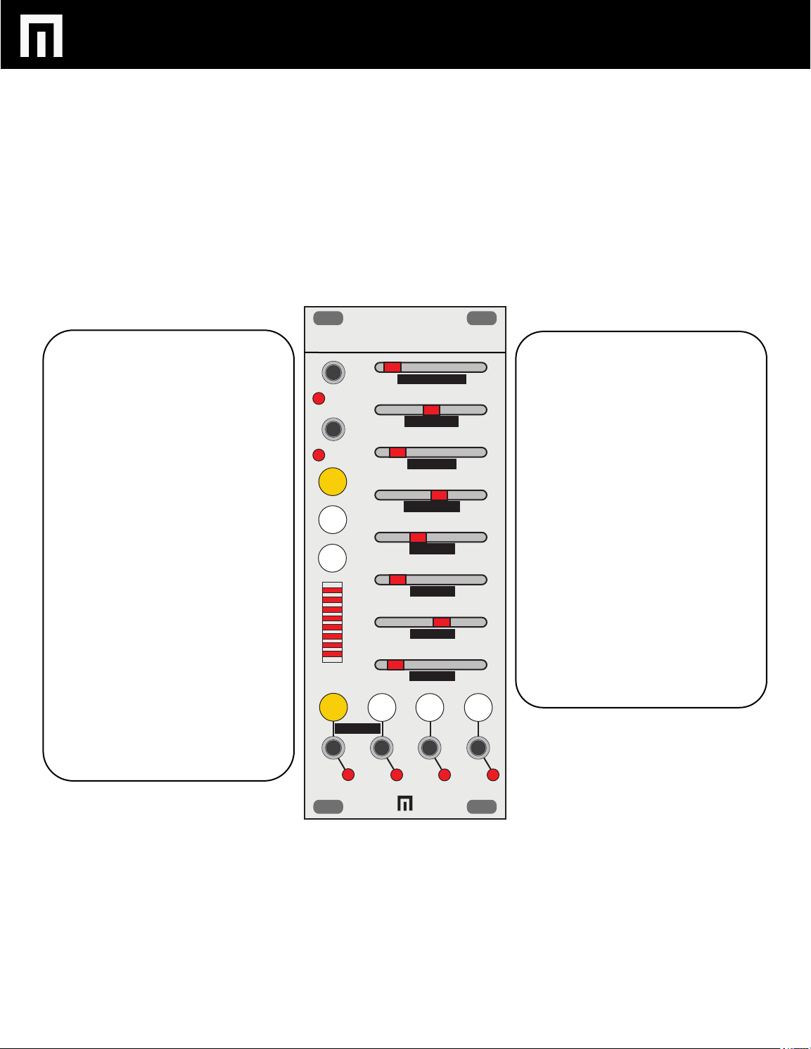
The following parameters are set on a
per-step level: PROBABILITY, REPEAT,
and DELAY.
PROBABILITY - This parameter controls
the chance of a step being active.
EXAMPLE: (make sure you have connected a cable from Channel A to a sound
source like a drum module, “trigger input”).
Select button for Channel A, then select
button PROBABILITY, then adjust the
fader for Step 1. You will now notice that
Step 1 rate of probability that the gate will
trigger has increased according the
amount that the fader is moved either left
or right. Now move the faders for Step
2-8.
Repeat the above example for Channel B,
C, and D with other modules/trigger inputs.
If you want the probability behavior to act
like a standard gate sequencer (always
sending a gate on step), simply move the
fader for the corresponding step all the
way to the left or to the right.
VARIGATE 4
TEMPO COARSE
CLK IN
TEMPO FINE
RESET
PROB
REPEAT
DELAY
A B C D
GLOBAL
CLK DIVIDE
PULSEWIDTH
A LENGTH
B LENGTH
C LENGTH
D LENGTH
REPEAT - This parameter controls the
amount of pulses per step. This can be
adjusted from 1-8 pulses.
EXAMPLE: Follow the same instructionsfor PROBABILITY, but select REPEAT
instead.
DELAY - This parameter introduces delay
on the selected step much like adding
shuffle. It will always fall within the step
being adjusted. The delay amount is
based on the clock rate so tempo
changes will not alter the pattern.
EXAMPLE: Follow the same instructionsfor PROBABILITY, or REPEAT but select
the DELAY instead.
To erase any of the above settings, simply
hold the buttons for PROB, REPEAT and
.
DELAY for 1 second.
MALEKKOHEAVYINDUSTRY.COM
Page 9
VARIGATE 4 MANUAL V.1
RANDOMIZER
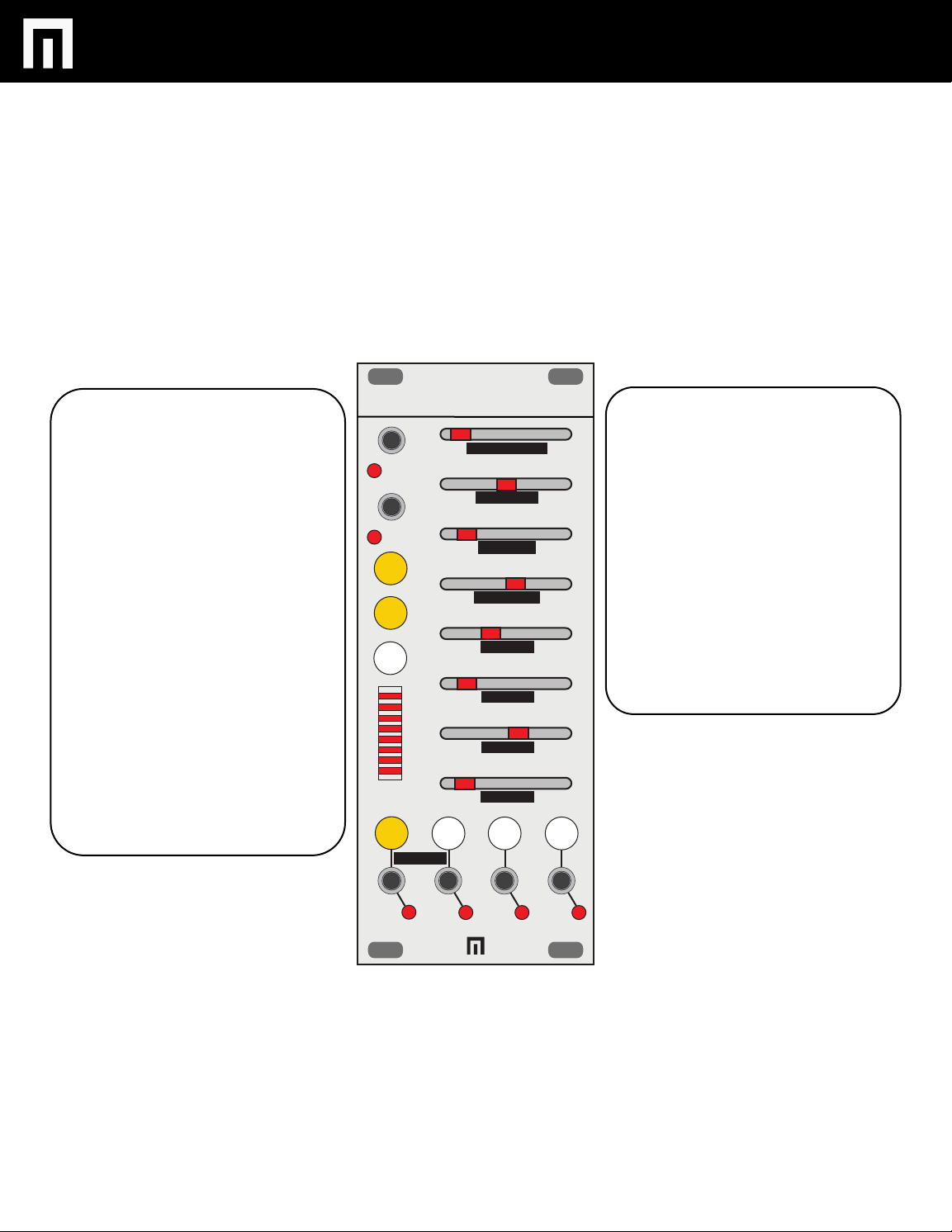
Pressing the PROBABILITY and REPEAT
buttons at the same time will enter the
randomizer setting for repeats.
Pressing the PROBABILITY and DELAY
buttons at the same time will enter the
randomizer setting for delay.
When in the randomizer setting, the
button’s LED will flash.
EXAMPLE 1:
Select Channel A button, hold the
PROBABILITY and REPEAT buttons at
the same time until they are blinking, and
then adjust Step 1 fader to the left or right
(left being minimum and right being
maximum). You will notice that the
amount of repeats will become more or
less random depending on the position of
Step 1 fader. Now move Step 2-8 faders
and notice each Step adopting more or
less random repeats.
VARIGATE 4
TEMPO COARSE
CLK IN
TEMPO FINE
RESET
PROB
REPEAT
DELAY
A B C D
GLOBAL
CLK DIVIDE
PULSEWIDTH
A LENGTH
B LENGTH
C LENGTH
D LENGTH
EXAMPLE 2:
Select Channel A, hold the PROBABILITY
and DELAY buttons at the same time until
they are blinking, and then adjust Step 1
fader to the left or right (left being
minimum and right being maximum). You
will notice that the amount of delay added
to Step 1 becomes more or less random
depending on the position of Step 1 fader.
Now move Step 2-8 faders and notice
each Step adopting more or less random
repeats.
Now apply these instructions to Channels
B, C and D as well.
MALEKKOHEAVYINDUSTRY.COM
Page 10
VARIGATE 4 MANUAL V.1
GLOBAL MODE
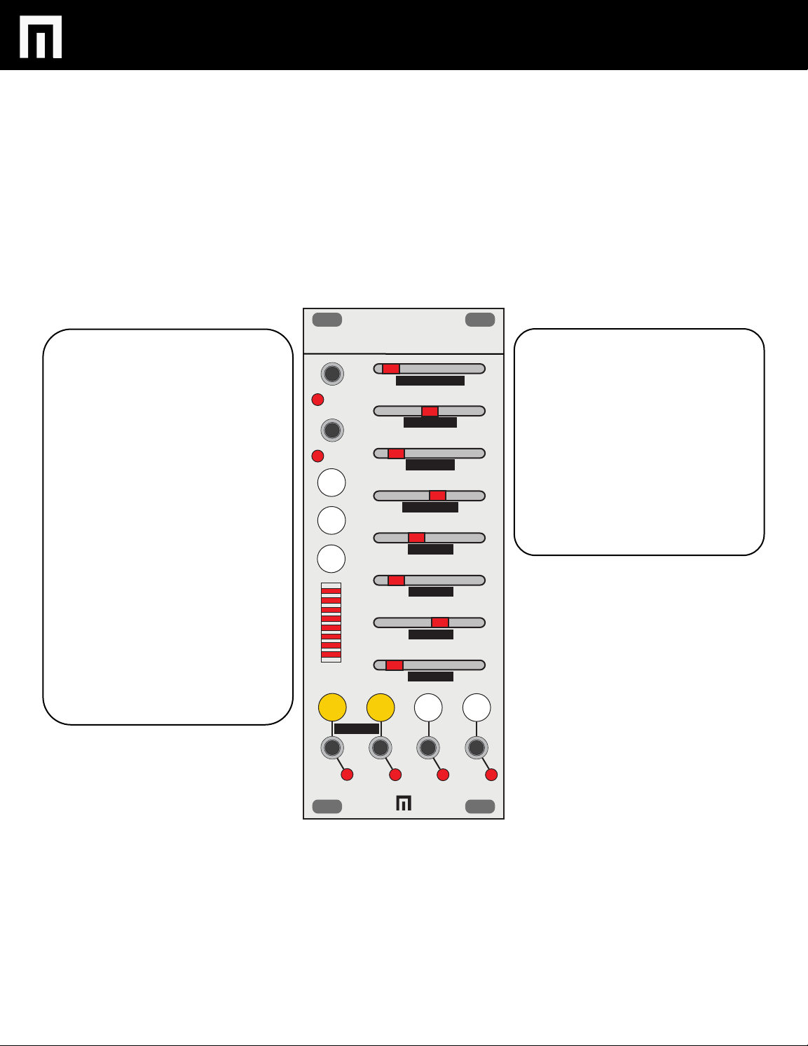
To enter the GLOBAL MODE and access
the GLOBAL MENU, press Channel A
and Channel B buttons at the same time.
Pressing these buttons again exits the
global menu. Global parameters are listed
under each slider on the front panel and
are as follows.
TEMPO COARSE - This parameter
adjusts the internal clock between 30 and
255 BPM
TEMPO FINE - This parameter adjusts
the clock +/- 25 BPM
CLOCK DIVIDE - This parameter divides
the internal or external clock by a factor of
1 to 8
PULSEWIDTH - This parameters adjusts
the length of gates on the output between
a pulsewidth of 20% and 80%
VARIGATE 4
TEMPO COARSE
CLK IN
TEMPO FINE
RESET
PROB
REPEAT
DELAY
A B C D
GLOBAL
CLK DIVIDE
PULSEWIDTH
A LENGTH
B LENGTH
C LENGTH
D LENGTH
A LENGTH - Sequence length of Channel
A (1-8)
B Length - Sequence length of Channel B
(1-8)
C Length - Sequence length of Channel C
(1-8)
D Length - Sequence length of Channel D
(1-8)
.
MALEKKOHEAVYINDUSTRY.COM
Page 11
VARIGATE 4 MANUAL V.1
SAVING PRESETS
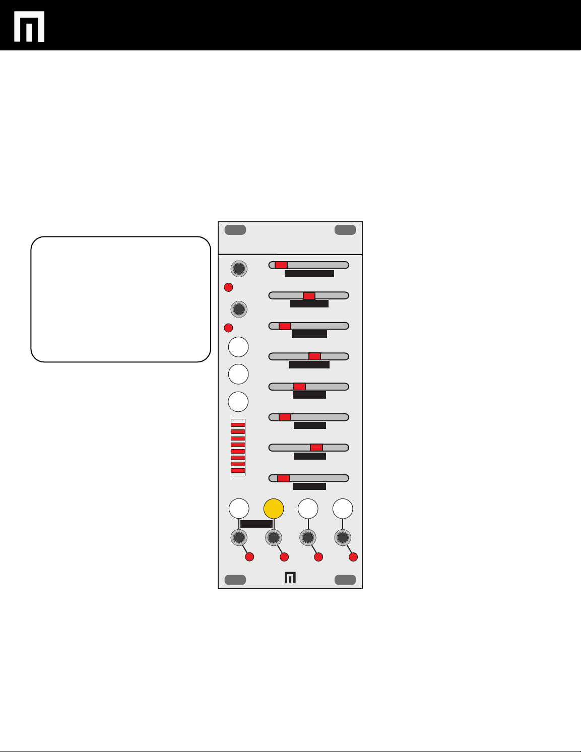
To save a preset hold one of the 4
channel buttons (A-D) for a second to
save to that preset slot. To recall double
tap the channel button to recall the
preset. The active preset is shown by the
blinking channel light.
VARIGATE 4
TEMPO COARSE
CLK IN
TEMPO FINE
RESET
PROB
REPEAT
DELAY
A B C D
GLOBAL
CLK DIVIDE
PULSEWIDTH
A LENGTH
B LENGTH
C LENGTH
D LENGTH
MALEKKOHEAVYINDUSTRY.COM
Page 12

VARIGATE 4 MANUAL V.1
WARRANTY
This product is covered by the Malekko Heavy Industry warranty, for one year
following the date of purchase. This warranty covers any defect in the
manufacturing of this product. This warranty does not cover any damage or
malfunction caused by incorrect use – such as, but not limited to, power cables
connected backwards, excessive voltage levels, or exposure to extreme
temperature or moisture levels. The warranty covers replacement or repair, as
decided by Malekko Heavy Industry. Please visit our website
malekkoheavyindustry.com to obtain full warranty information and to register
your product for coverage.
MALEKKOHEAVYINDUSTRY.COM
 Loading...