

Page 1
P 1/ 10
PRODUCT
CONCEPT AND MAIN APPLICATIONS
Specification
Standard equipment
Optional accessories
Note: The standard equipment for the tool shown above may vary by country.
Model No.
Description
MT817, MT818
Hammer Drills 13mm (1/2")
Models MT817 and MT818 have been developed as the cosmetic
change of maktec hammer drills MT811 and MT812.
Their main features are:
• Industrial performance and durability at less expense
• Ergonomically designed handle with rubberized soft grip
The specification difference between these models are:
MT817/ 13mm (1/2") hammer drill with Keyed chuck
MT818/ 13mm (1/2") hammer drill with Keyless chuck
These models are also available with plastic carrying case
as “K” models; MT817K, MT818K
No
110
120
230
240
4.1 50/60
50/60
50/60
50/60
3.8
2.0
1.9
430
---
430
430
220
220
220
220
340
340
340
220 50/602.1 430 220 340
340
Continuous Rating (W)
Voltage (V) Cycle (Hz)
Input Output
Max. Output (W)Current (A)
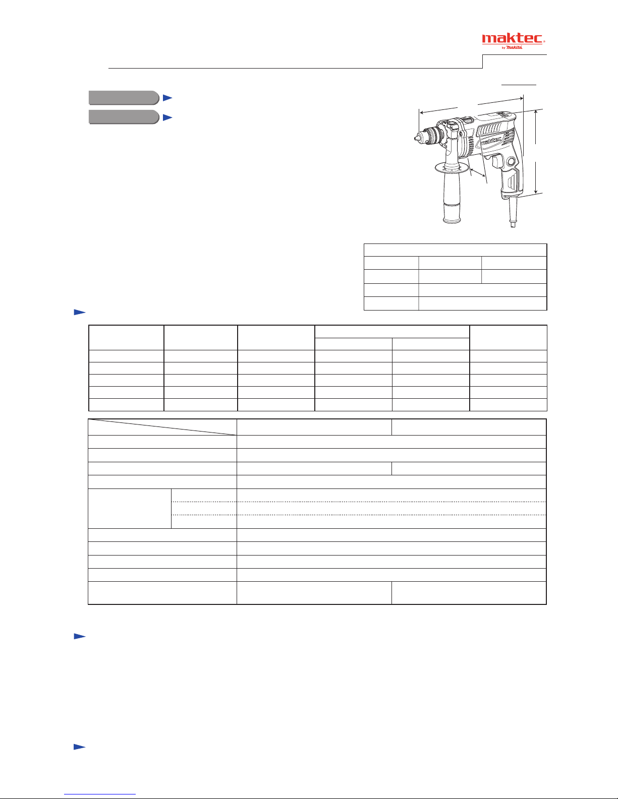
Dimensions: mm ( " )
Width (W)
Height (H)
Length (L)
Model No.
(The image above is MT817.)
MT817 MT818
255 (10) 258 (10-1/8)
193 (7-5/8)
72 (2-13/16)
Chuck capacity: mm (")
Chuck type
Reverse switch
Impacts per min.: min.
ˉ¹= ipm
Capacities: mm (")
Steel
Concrete
Wood
Protection against electric shock
Power supply cord: m (ft)
Weight according to
EPTA-Procedure 01/2003*: kg (lbs)
0 - 2,800
Model No.
MT817
0 - 30,800
Keyed
1.5 - 13 (1/16 - 1/2)
13 (1/2)
13 (1/2)
18 (11/16)
Yes
Double insulation
1.8 (3.9)
2.0 (6.6)
MT818
Keyless
1.7 (3.7)
Variable speed control by trigger Yes
* with Side grip
Chuck key S-13 ................................................ 1 (MT817 only)
Key holder 10 ................................................... 1 (MT817 only)
Side grip ........................................................... 1
Depth gauge ..................................................... 1 (for some countries)
Cap ................................................................... 1 (for some countries)
Plastic carrying case ........................................ 1 ("K models" only)
No load speed: min.
ˉ¹=rpm
Specification
T
ECHNICAL INFORMATION
H
W
L
Page 2
P 2/ 10
[1] NECESSARY REPAIRING TOOLS
CAUTION: Repair the machine in accordance with “Instruction manual” or “Safety instructions”.
Code No. Description Use for
1R004 Retaining ring pliers ST-2 removing Retaining ring WR12 from Spindle
1R005 Retaining ring pliers RT-2N removing Retaining ring R-32 from Gear housing
1R026 Bearing setting pipe 16-8.2 removing Spindle from Helical gear 37
1R028 Bearing setting pipe 20-12.2 assembling Helical gear 37 and Cam
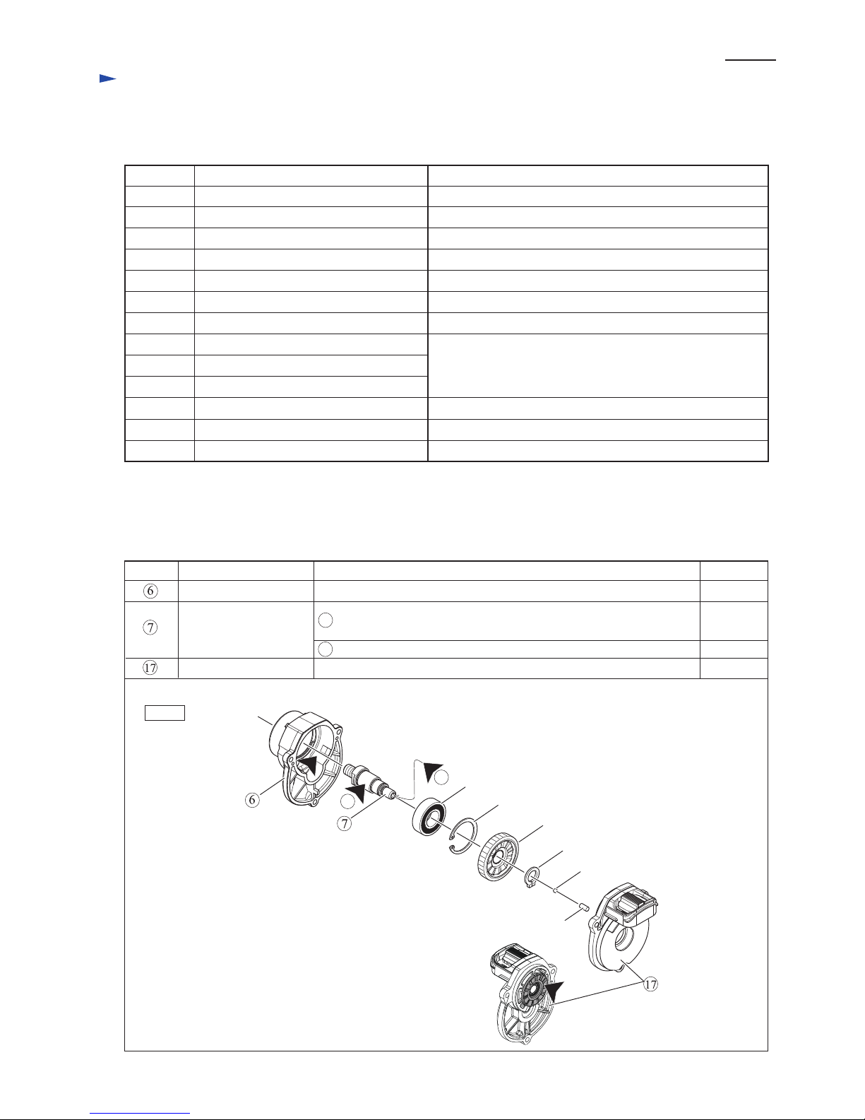
[2] LUBRICATION
Apply Makita grease N. No.2 to the following portions designated with the black triangle to protect
parts and product from unusual abrasion.
Fig. 1
Item No. Description
Gear housing 4g
a little
a little
a little
Gear room where Helical gear 37 rotates
Cam portion
Hole where Steel ball 3.5 and Pin 4 are assembled
Where Ball bearing 6002DDW touches drum portion
(when using in Hammer drill mode)
Cam housing complete
Spindle
Steel ball 3.5
Retaining ring WR12
Viewing from
Helical gear 37 side
Retaining ring R-32
Pin 4
AmountPortion to lubricate
1R035
1R037
1R139
1R223
1R224
1R258
1R269
1R283
1R298
Bearing setting plate 15.2 holding spindle when assembling Helical gear 37
Bearing setting plate 20.2 holding Gear housing when removing Spindle
holding Gear housing cover when assembling Cam
Drill chuck extractor fixing Spindle, when Drill Chuck removing
Torque wrench shaft 20-90N.m
removing / assembling Drill chuck
removing Ball bearings
Ratchet head 12.7 (For 1R223)
V block
Bearing extractor
Round bar for arbor 9-50 removing Spindle from Helical gear 37
Hex bar 10 with square socket
Helical gear 37
Ball bearing 6002DDW
7a
7b
7a
7b
Repair
Page 3
P 3/ 10
[3] DISASSEMBLY/ASSEMBLY
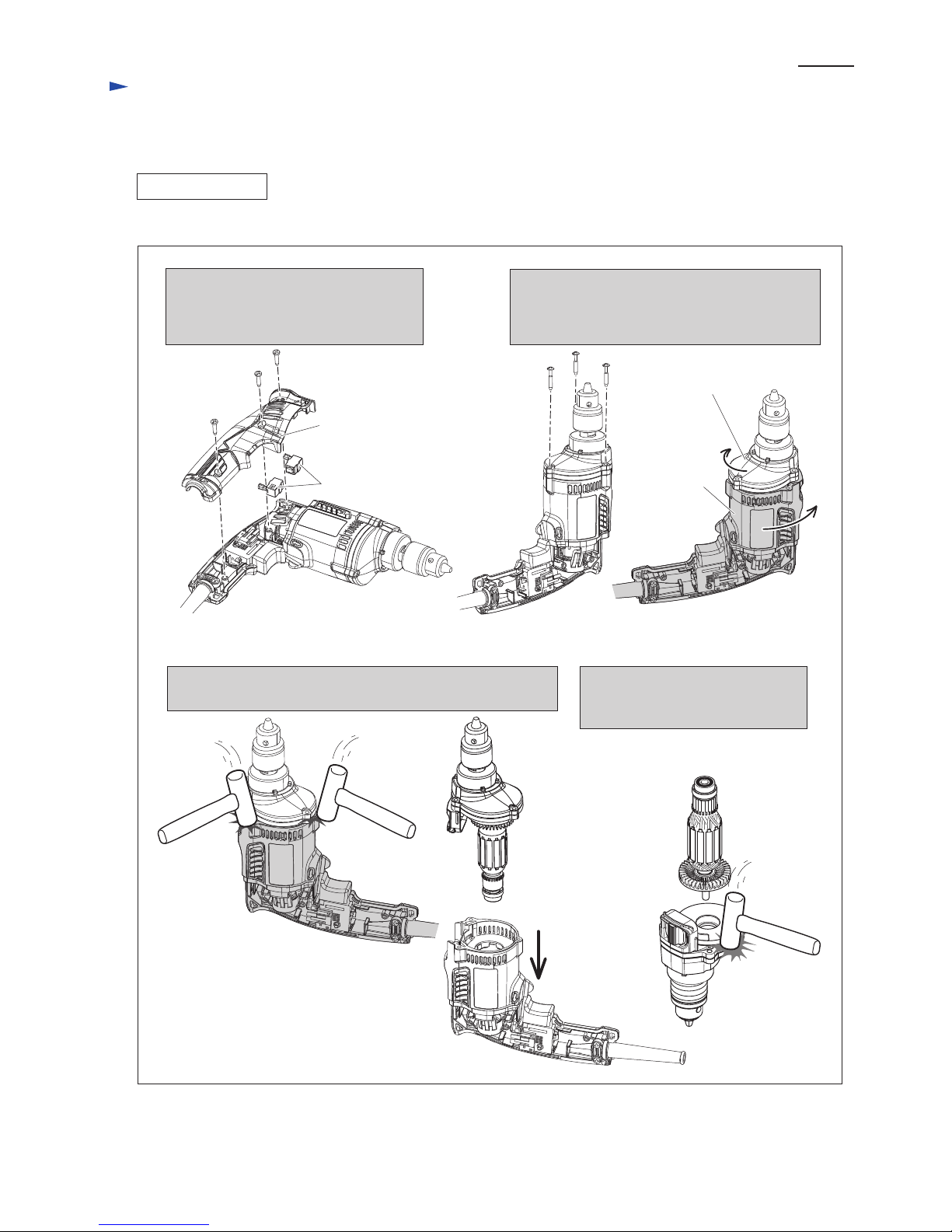
[3] -1. Armature
DISASSEMBLING
1. Remove Handle cover by loosening
three 4x18 Tapping screws. And then,
remove Carbon brushes together with
Brush holders.
2. Remove three 5x25 Tapping screws.
And then, twist Motor housing or Gear housing
so that the edge of Motor housing can be tapped
with plastic hammer to disassemble.
3. Separate Motor housing from Gear housing section by striking
its edge with plastic hammer.
4x18 Tapping
screw
Handle cover
Motor housing
Gear housing
Brush holder
4. Disassemble Armature from Cam
housing complete by striking its
edge with plastic hammer.
[3] DISASSEMBLY/ASSEMBLY
[3] -1. Armature
DISASSEMBLING
1. Remove Handle cover by loosening
three 4x18 Tapping screws. And then,
remove Carbon brushes together with
Brush holders.
2. Remove three 5x25 Tapping screws.
And then, twist Motor housing or Gear housing
so that the edge of Motor housing can be tapped
with plastic hammer to disassemble.
3. Separate Motor housing from Gear housing section by tapping
its edge with plastic hammer.
4x18 Tapping
screw
Handle cover
(1) Disassemble Armature from the machine as drawn in Fig. 2.
Motor housing
Gear housing
Brush holders with
Carbon brushes
4. Disassemble Armature from Cam
housing complete by tapping its
edge with plastic hammer.
Fig. 2
Repair
Page 4
P 4/ 10
[3] DISASSEMBLY/ASSEMBLY
[3] -1. Armature (cont.)
DISASSEMBLING
[3] -2. Drill Chuck
ASSEMBLING
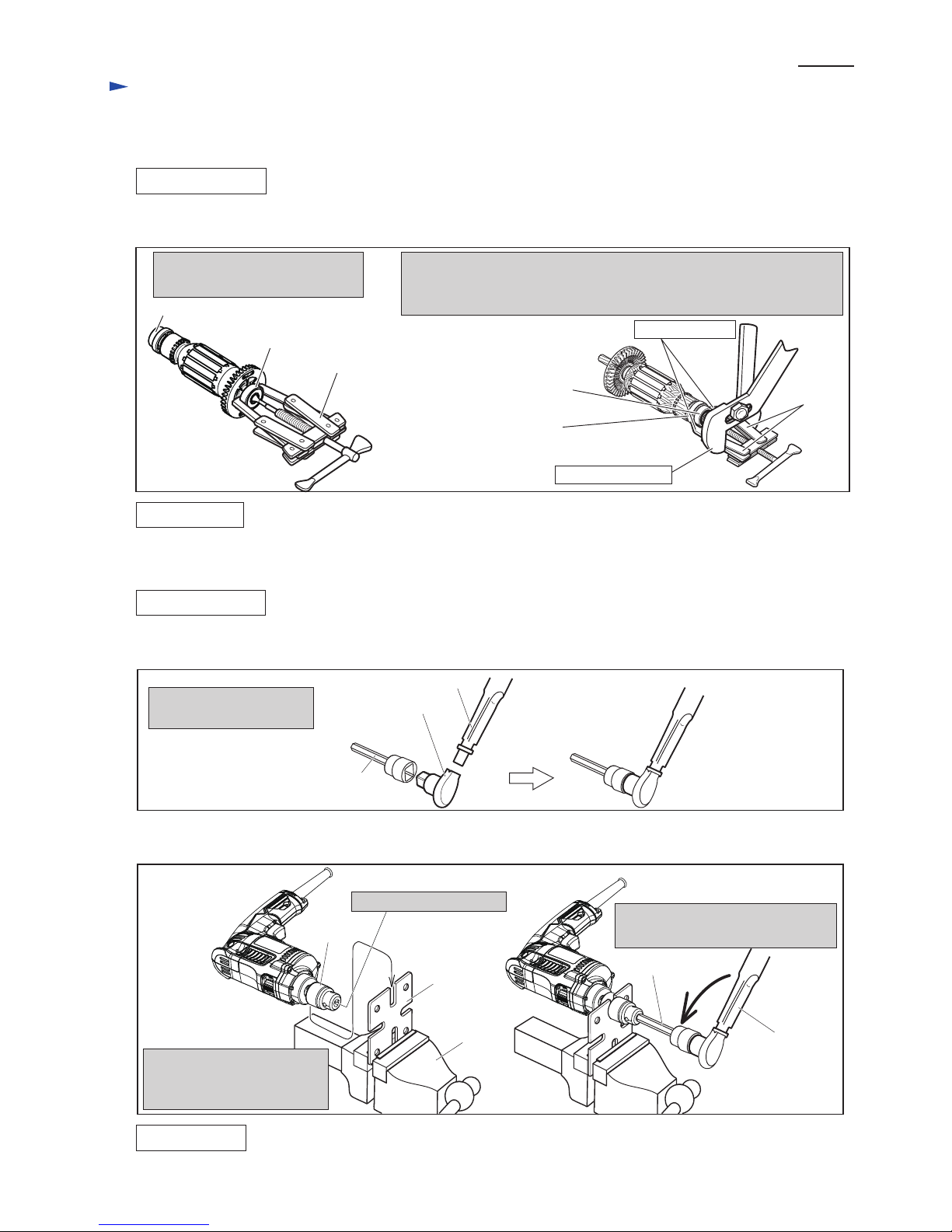
(2) Remove Ball bearings from Armature shaft as drawn in Fig. 3.
Assemble by reversing the disassembly procedure. Refer to Figs. 3 and 2.
1. Remove Ball bearing 608DDW
with 1R269.
2. The claws of 1R269 cannot hold Ball bearing 607ZZ firmly because of
the small gap between the bearing and insulation washer. So use Water
pump pliers to secure the legs firmly as shown below.
Water pump pliers
Claws of 1R269
Fig. 3
Ball bearing 607ZZ
Insulation washer
Legs
Ball bearing 608DDW
1R269
Ball bearing 607ZZ
Repair
DISASSEMBLING
1. Attach 1R224 to 1R223.
2. Attach 1R298 to R224.
(1) Arrange the repairing tools as drawn in Fig. 4.
(2) Remove 13 mm Drill chuck as drawn in Fig. 5.
Fig. 4
Fig. 5
1R224
1R223
R139
1R298
1R298
1R223
Vise
Drill chuck
1. Open the Drill chuck.
2. Fix 1R139 to Vise and set
Drill chuck to the groove of
1R139.
3. Insert 1R298 into Drill chuck
and turn 1R223 counterclockwise.
ASSEMBLING
Assemble by reversing the disassembly procedure. Refer to Figs. 5 and 4.
Note: Set the fastening torque of 1R223 to 26.0 N.m ~ 30.10 N.m (265 Kgfcm ~ 306 Kgfcm) and turn 1R223 clockwise.
Page 5
Repair
P 5/ 10
Retaining ring
WR-12
Spindle
[3] DISASSEMBLY/ASSEMBLY
DISASSEMBLING
Fig. 6
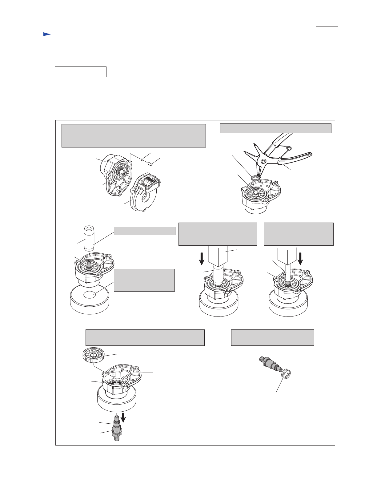
[3] -3. Helical Gear 37 and Ball bearing 6002DDW
(1) Remove Drill chuck as drawn in Figs. 4 and 5.
(2) Separate Gear housing from Motor housing. And remove Armature from Cam housing complete
as drawn in Fig. 2.
(3) Disassemble Helical gear 37 as drawn in Fig. 6.
1. Separate Cam housing complete from Gear housing.
Take out Pin 4 and Steel ball 3.5 from the hole of Spindle
so as not to lose them.
2. Remove Retaining ring WR-12 with 1R004.
Cam housing
complete
Gear housing
Steel ball 3.5
Pin 4
1R004
3. Put Gear housing onto
1R037 while fitting
Spindle to the hole.
Spindle
1R037
1R026
4. Put 1R026 on Spindle.
5. Press 1R026 with Arbor press
so that Spindle is pushed out
slightly.
6. Put 1R238 on Spindle and
press 1R283 with Arbor
press to remove Spindle.
7. Helical gear 37 and Spindle (with Compression
spring 16) are removed from Gear housing.
8. Remove Compression spring 16
from Spindle.
1R026
Arbor press
1R283
Spindle
Spindle
1R037 1R037
Helical gear 37
Ball bearing
6002DDW
Gear housing
Spindle
Compression
spring 16
Compression
spring 16
Page 6
Repair
P 6/ 10
[3] DISASSEMBLY/ASSEMBLY
DISASSEMBLING
ASSEMBLING
Fig. 7
Fig. 8
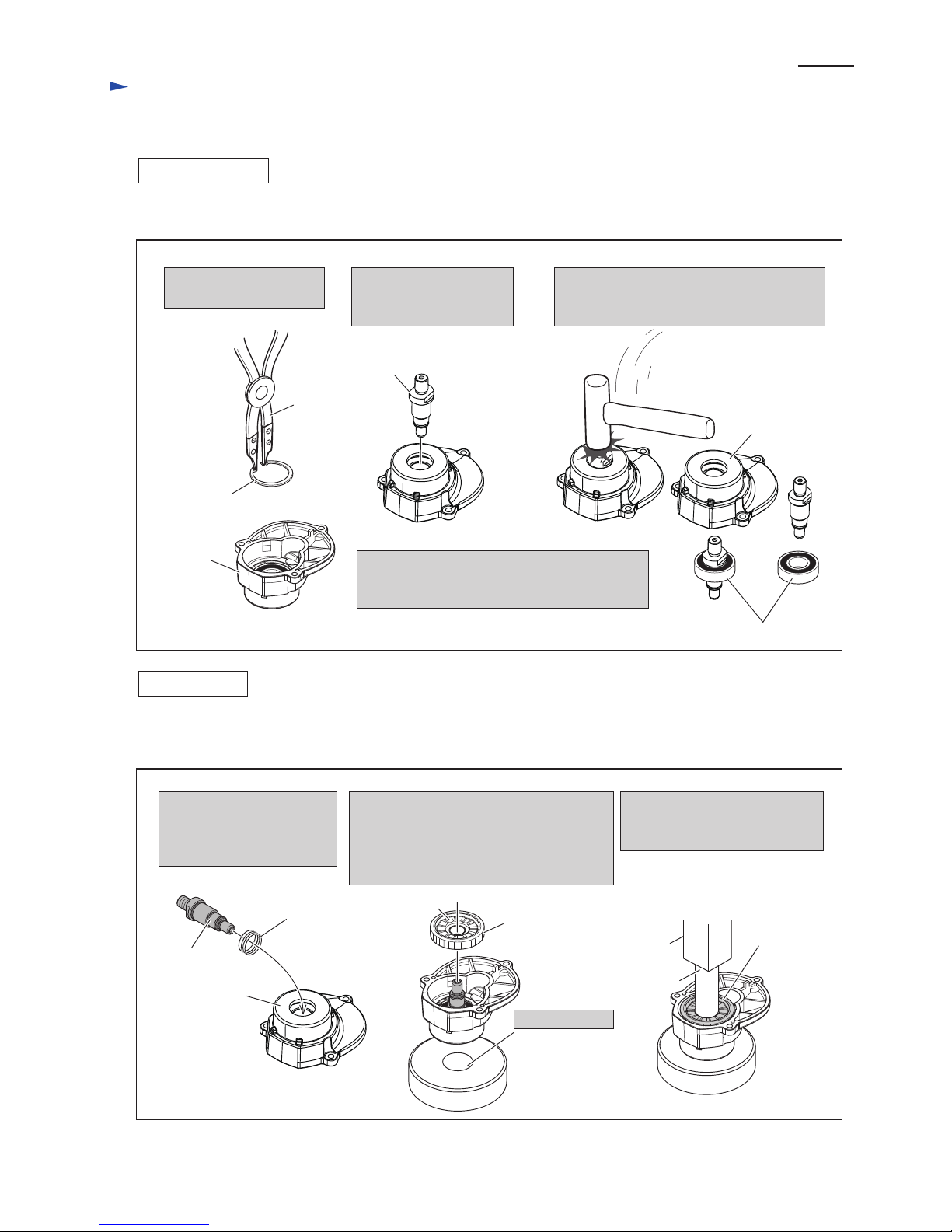
[3] -3. Helical Gear 37 and Ball bearing 6002DDW (cont.)
(4) Remove Ball bearing 6002DDW as drawn in Fig. 7.
(1) Assemble Ball bearing 6002DDW to Gear housing. And then, secure it with Retaining ring R-32. Refer to Fig. 7.
(2) Assemble Spindle and Helical gear 37 as drawn in Fig. 8.
1. Remove Retaining
ring R-32 with 1R005.
2. Insert Spindle into Ball
bearing 6002DDW
to use Spindle as a jig.
3. Strike the head of the re-inserted Spindle
with Plastic hammer.
Then, Ball bearing 6002DDW is removed.
Ball bearing 6002DDW
Gear
housing
Retaining
ring R-32
Spindle
1R005
Gear housing
Compression
spring 16
1. Pass Spindle through
Compression spring 16
and insert the Spindle into
Ball bearing 6002DDW.
2. Put Gear housing onto 1R035 while
aligning the inserted Spindle head with
the hole of 1R035. Set Helical gear 37 to
Spindle with the Cam portion facing to
Cam housing complete side.
3. Press 1R028 with Arbor press.
Then, Helical gear 37 is
installed on Spindle properly.
1R035
Helical gear 37
Helical gear 37
Gear housing
Spindle
1R028
Arbor press
Cam portion
(3) Assemble Retaining ring WR-12, Steel ball 3.5 and Pin 4 to Spindle. Refer to the drawing on the upper left
and right in Fig. 6.
Hole of 1R035
Note: When Helical gear 37 is removed,
Ball bearing 6002DDW has damage.
Do not reuse the Ball bearing 6002DDW.
Page 7
Repair
P 7/ 10
[3] DISASSEMBLY/ASSEMBLY
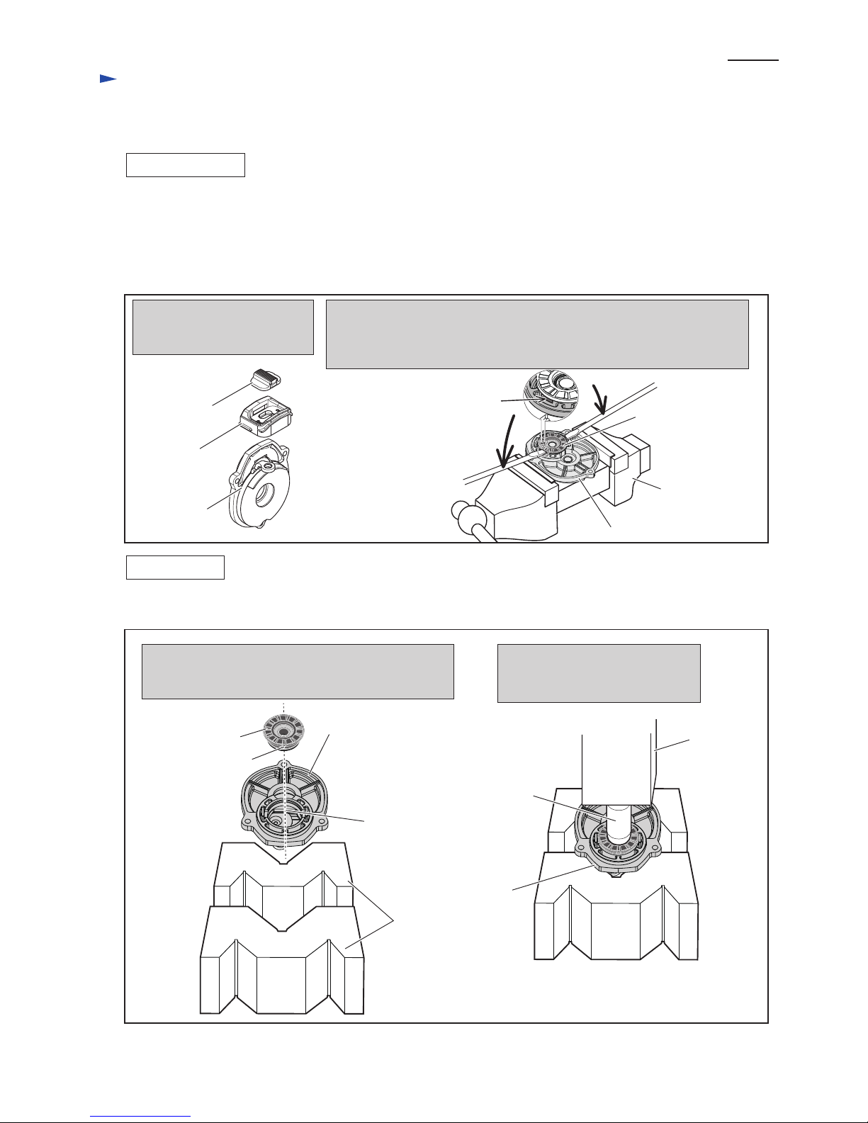
[3] -4. Cam Housing Compete
DISASSEMBLING
ASSEMBLING
Fig. 9
Fig. 10
2. Remove Cam complete as follows:
(1) Fix Cam housing to Vise.
(2) Insert two slotted head screwdrivers into the cuts between Cam complete
and Cam housing to remove Cam complete.
1. Remove Change lever and
Lever case from Cam housing
complete.
(1) Remove Drill chuck as drawn in Figs. 4 and 5.
(2) Separate Gear housing from Motor housing. And remove Armature from Cam housing complete
as drawn in Fig. 2.
(3) Separate Cam housing complete from Gear housing. See the drawing on the upper left in Fig. 6.
(4) Disassemble Cam complete as drawn in Fig. 9.
(1) Assemble Cam complete to Cam housing as drawn in Fig. 10.
(2) Assemble Lever case and Change lever. Refer to Fig. 9.
Lever case
Cam housing
complete
Change lever
Cut on Cam
housing complete
Cam complete
Vise
Cam housing
Center line of
Cam housing
1. Set Cam complete to Cam housing with the notch of
cam complete aligning with the center line on Cam
housing. And then, put the Cam housing on 1R258.
2. Press 1R028 with Arbor press.
This ends the assembling of Cam
housing complete.
Notch
Cam complete
Cam housing
1R028
Arbor press
Cam housing
complete
1R258
Page 8
P 8/ 10
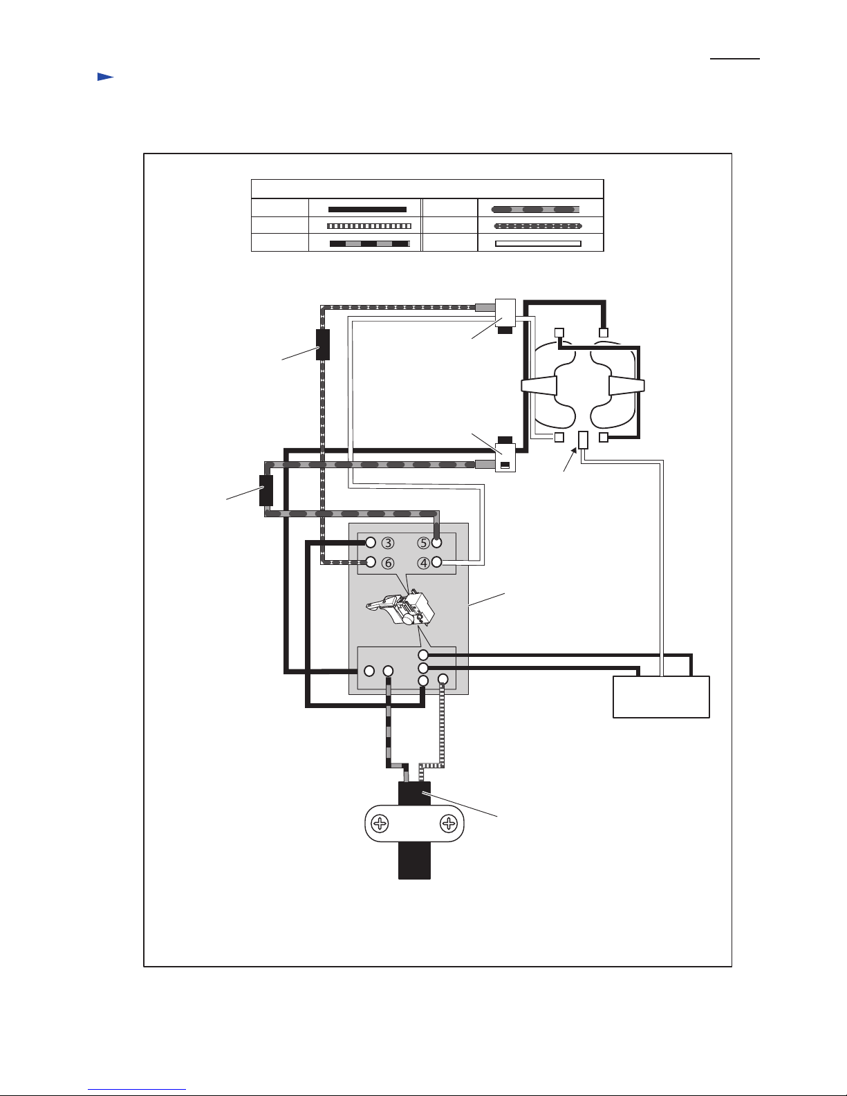
Fig. D-1
Orange
White
Blue
Brown
Purple
Color index of lead wires' sheath
Switch
Chike coil
Chike coil
Field
Brush
holder A
Brush
holder B
Black
2a
2
2b
1b
1
1a
Noise
suppressor
Power supply cord
Earth terminal
(It depends on
specifications.)
Viewed from commutator
Circuit diagram
Page 9
P 9/ 10
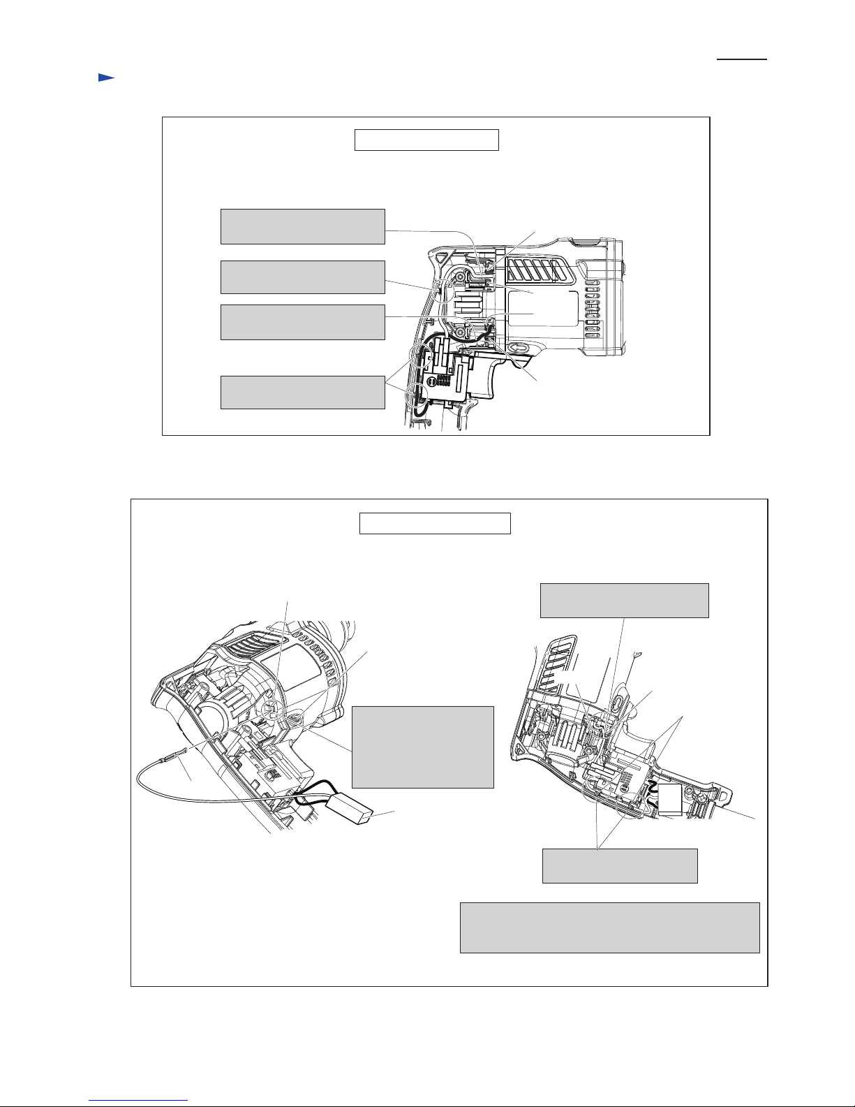
Wiring of Field lead wire
Rib C
Rib D
Rib A
Rib B
Wiring of Earth lead wire
Fig. D-2
Fig. D-3
arrow
slit
Terminal
Noise suppressor
Lead wire
holders
Rib E
Rib D
1. Insert terminal of the
earth lead wire (white)
into the slit near the
arrow showing the
rotating direction.
3. Fix the lead wire (white)
in Lead wire holders.
Route Field lead wire (white)
between Rib A and Rib B.
Route Field lead wire (black)
between Rib C and Rib D.
Route Field lead wire (white)
through the groove.
Route Field lead wire (black)
through Lead wire holders.
2. Route the Lead wire (white)
between Rib D and Rib E.
Note: Do not route the earth lead wire (white) over the
top of the cables when routing the lead wires
through Lead wire holders.
Wiring diagram
Page 10
Wiring diagram
P 10/ 10
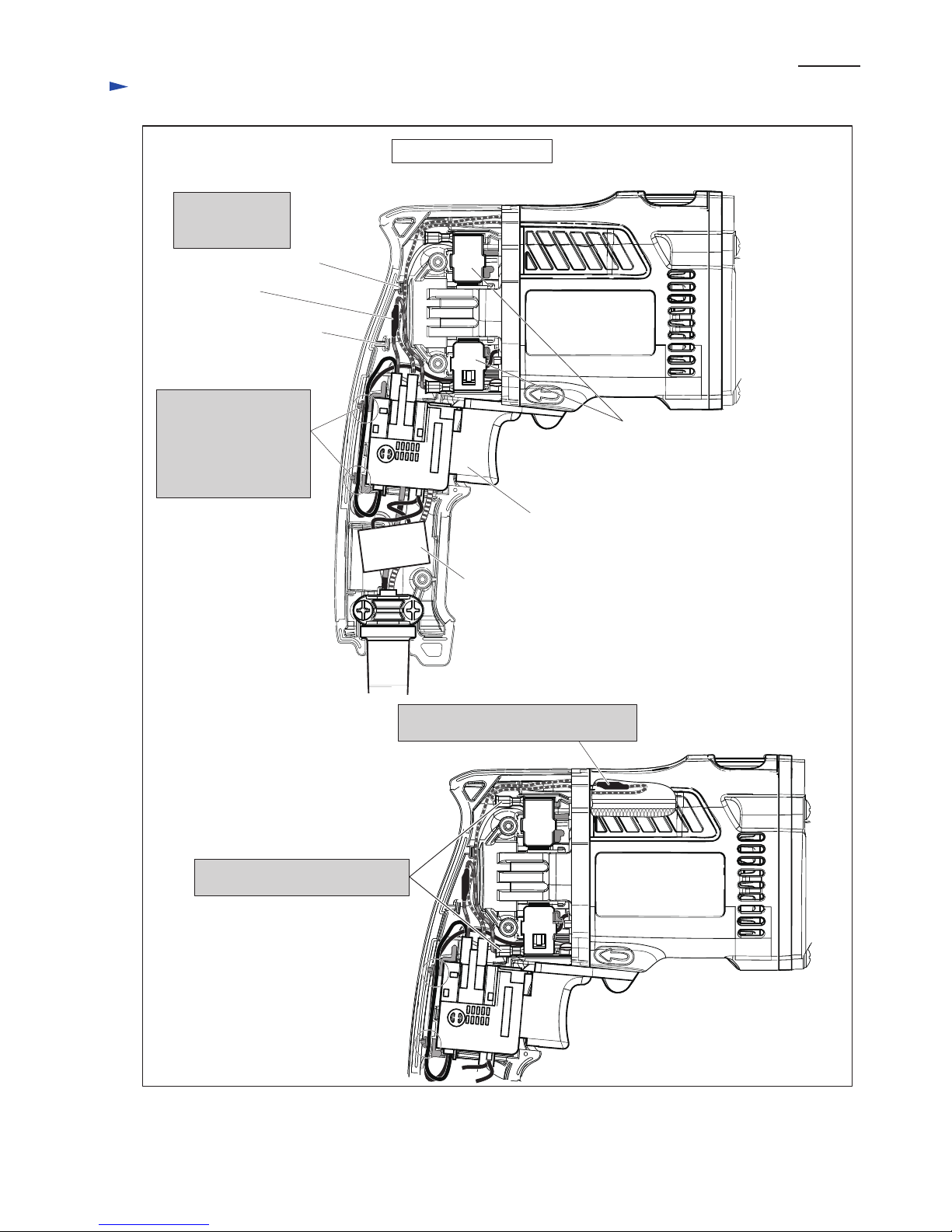
Wiring in Handle section
Rib F
Choke coil
(orange)
Put Choke coil
(orange) between
Rib F and Rib G.
Rib G
Fig. D-4
Noise suppressor
Switch
Brush holders
Do not route the earth
lead wire (white) over
the top of the cables
when routing the lead
wires through Lead wire
holders.
Put Choke coil (purple) in the position
shown below.
Connect the Connecting terminals
to Brush holders from the rear side.
 Loading...