

Page 1
1
ENGLISH (Original instructions)
INSTRUCTION MANUAL
DOUBLE INSULATION
IMPORTANT: Read Before Using.
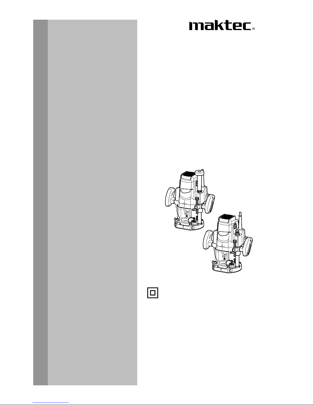
Router
MT362
013290
Page 2
2
ENGLISH (Original instructions)
SPECIFICATIONS
Model MT362
Collet chuck capacity 12 mm or 1/2"
Plunge capacity 0 - 60 mm
No load speed (min-1) 22,000
Overall height 300 mm
Net weight 5.5 kg
Safety class /II
• Due to our continuing program of research and development, the specifications herein are subject to change without notice.
• Specifications may differ from country to country.
• Weight according to EPTA-Procedure 01/2003
END201-6
Symbols
The following show the symbols used for the equipment.
Be sure that you understand their meaning before use.
・ Read instruction manual.
・ DOUBLE INSULATION
・ Only for EU countries
Do not dispose of electric equipment
together with household waste
material!
In observance of European Directive
2012/19/EU on waste electric and
electronic equipment and its
implementation in accordance with
national law, electric equipment that
have reached the end of their life must
be collected separately and returned to
an environmentally compatible
recycling facility.
ENE010-1
Intended use
The tool is intended for flush trimming and profiling of
wood, plastic and similar materials.
ENF002-2
Power supply
The tool should be connected only to a power supply of
the same voltage as indicated on the nameplate, and
can only be operated on single-phase AC supply. They
are double-insulated and can, therefore, also be used
from sockets without earth wire.
ENF100-1
For public low-voltage distribution systems of
between 220 V and 250 V.
Switching operations of electric apparatus cause
voltage fluctuations. The operation of this device under
unfavorable mains conditions can have adverse effects
to the operation of other equipment. With a mains
impedance equal or less than 0.35 Ohms it can be
presumed that there will be no negative effects. The
mains socket used for this device must be protected
with a fuse or protective circuit breaker having slow
tripping characteristics.
ENG905-1
Noise
The typical A-weighted noise level determined
according to EN60745:
Sound pressure level (LpA) : 86 dB(A)
Sound power level (L
WA
) : 97 dB(A)
Uncertainty (K) : 3 dB(A)
Wear ear protection
ENG900-1
Vibration
The vibration total value (tri-axial vector sum)
determined according to EN60745:
Work mode : cutting grooves in MDF
Vibration emission (a
h
) : 2.5 m/s
2
Uncertainty (K) : 1.5 m/s
2
ENG901-1
•
The declared vibration emission value has been
measured in accordance with the standard test
method and may be used for comparing one tool
with another.
• The declared vibration emission value may also be
used in a preliminary assessment of exposure.
Page 3

3
WARNING:
• The vibration emission during actual use of the
power tool can differ from the declared emission
value depending on the ways in which the tool is
used.
• Be sure to identify safety measures to protect the
operator that are based on an estimation of
exposure in the actual conditions of use (taking
account of all parts of the operating cycle such as
the times when the tool is switched off and when it
is running idle in addition to the trigger time).
ENH101-16
For European countries only
EC Declaration of Conformity
We Makita Corporation as the responsible
manufacturer declare that the following Makita
machine(s):
Designation of Machine:
Router
Model No./ Type: MT362
are of series production and
Conforms to the following European Directives:
2006/42/EC
And are manufactured in accordance with the following
standards or standardised documents:
EN60745
The technical documentation is kept by:
Makita International Europe Ltd.
Technical Department,
Michigan Drive, Tongwell,
Milton Keynes, Bucks MK15 8JD, England
7.5.2012
000230
Tomoyasu Kato
Director
Makita Corporation
3-11-8, Sumiyoshi-cho,
Anjo, Aichi, 446-8502, JAPAN
GEA005-3
General Power Tool Safety
Warnings
WARNING Read all safety warnings and all
instructions. Failure to follow the warnings and
instructions may result in electric shock, fire and/or
serious injury.
Save all warnings and
instructions for future reference.
The term "power tool" in the warnings refers to your
mains-operated (corded) power tool or battery-operated
(cordless) power tool.
Work area safety
1. Keep work area clean and well lit. Cluttered or
dark areas invite accidents.
2. Do not operate power tools in explosive
atmospheres, such as in the presence of
flammable liquids, gases or dust. Power tools
create sparks which may ignite the dust or fumes.
3. Keep children and bystanders away while
operating a power tool. Distractions can cause
you to lose control.
Electrical safety
4. Power tool plugs must match the outlet. Never
modify the plug in any way. Do not use any
adapter plugs with earthed (grounded) power
tools. Unmodified plugs and matching outlets will
reduce risk of electric shock.
5. Avoid body contact with earthed or grounded
surfaces such as pipes, radiators, ranges and
refrigerators. There is an increased risk of
electric shock if your body is earthed or grounded.
6. Do not expose power tools to rain or wet
conditions. Water entering a power tool will
increase the risk of electric shock.
7. Do not abuse the cord. Never use the cord for
carrying, pulling or unplugging the power tool.
Keep cord away from heat, oil, sharp edges or
moving parts. Damaged or entangled cords
increase the risk of electric shock.
8. When operating a power tool outdoors, use an
extension cord suitable for outdoor use. Use
of a cord suitable for outdoor use reduces the risk
of electric shock.
9. If operating a power tool in a damp location is
unavoidable, use a residual current device
(RCD) protected supply. Use of an RCD
reduces the risk of electric shock.
10. Use of power supply via a RCD with a rated
residual current of 30mA or less is always
recommended.
Page 4

4
Personal safety
11. Stay alert, watch what you are doing and use
common sense when operating a power tool.
Do not use a power tool while you are tired or
under the influence of drugs, alcohol or
medication. A moment of inattention while
operating power tools may result in serious
personal injury.
12. Use personal protective equipment. Always
wear eye protection. Protective equipment such
as dust mask, non-skid safety shoes, hard hat, or
hearing protection used for appropriate conditions
will reduce personal injuries.
13. Prevent unintentional starting. Ensure the
switch is in the off-position before connecting
to power source and/or battery pack, picking
up or carrying the tool. Carrying power tools
with your finger on the switch or energising power
tools that have the switch on invites accidents.
14. Remove any adjusting key or wrench before
turning the power tool on. A wrench or a key
left attached to a rotating part of the power tool
may result in personal injury.
15. Do not overreach. Keep proper footing and
balance at all times. This enables better control
of the power tool in unexpected situations.
16.
Dress properly. Do not wear loose clothing or
jewellery. Keep your hair, clothing, and gloves
away from moving parts.
Loose clothes, jewellery
or long hair can be caught in moving parts.
17. If devices are provided for the connection of
dust extraction and collection facilities,
ensure these are connected and properly
used. Use of dust collection can reduce dust-
related hazards.
Power tool use and care
18. Do not force the power tool. Use the correct
power tool for your application. The correct
power tool will do the job better and safer at the
rate for which it was designed.
19. Do not use the power tool if the switch does
not turn it on and off. Any power tool that
cannot be controlled with the switch is dangerous
and must be repaired.
20. Disconnect the plug from the power source
and/or the battery pack from the power tool
before making any adjustments, changing
accessories, or storing power tools. Such
preventive safety measures reduce the risk of
starting the power tool accidentally.
21. Store idle power tools out of the reach of
children and do not allow persons unfamiliar
with the power tool or these instructions to
operate the power tool. Power tools are
dangerous in the hands of untrained users.
22. Maintain power tools. Check for misalignment
or binding of moving parts, breakage of parts
and any other condition that may affect the
power tool’s operation. If damaged, have the
power tool repaired before use. Many
accidents are caused by poorly maintained power
tools.
23. Keep cutting tools sharp and clean. Properly
maintained cutting tools with sharp cutting edges
are less likely to bind and are easier to control.
24. Use the power tool, accessories and tool bits
etc. in accordance with these instructions,
taking into account the working conditions
and the work to be performed. Use of the
power tool for operations different from those
intended could result in a hazardous situation.
Service
25. Have your power tool serviced by a qualified
repair person using only identical
replacement parts. This will ensure that the
safety of the power tool is maintained.
26. Follow instruction for lubricating and
changing accessories.
27. Keep handles dry, clean and free from oil and
grease.
GEB018-4
ROUTER SAFETY WARNINGS
1. Hold power tool by insulated gripping
surfaces, because the cutter may contact its
own cord. Cutting a "live" wire may make
exposed metal parts of the power tool "live" and
shock the operator.
2. Use clamps or another practical way to secure
and support the workpiece to a stable
platform. Holding the work by your hand or
against the body leaves it unstable and may lead
to loss of control.
3. Wear hearing protection during extended
period of operation.
4. Handle the bits very carefully.
5. Check the bit carefully for cracks or damage
before operation. Replace cracked or
damaged bit immediately.
6. Avoid cutting nails. Inspect for and remove all
nails from the workpiece before operation.
7. Hold the tool firmly with both hands.
8. Keep hands away from rotating parts.
9. Make sure the bit is not contacting the
workpiece before the switch is turned on.
10. Before using the tool on an actual workpiece,
let it run for a while. Watch for vibration or
wobbling that could indicate improperly
installed bit.
Page 5
5
11. Be careful of the bit rotating direction and the
feed direction.
12. Do not leave the tool running. Operate the tool
only when hand-held.
13. Always switch off and wait for the bit to come
to a complete stop before removing the tool
from workpiece.
14. Do not touch the bit immediately after
operation; it may be extremely hot and could
burn your skin.
15. Do not smear the tool base carelessly with
thinner, gasoline, oil or the like. They may
cause cracks in the tool base.
16. Use bits of the correct shank diameter
suitable for the speed of the tool.
17. Some material contains chemicals which may
be toxic. Take caution to prevent dust
inhalation and skin contact. Follow material
supplier safety data.
18. Always use the correct dust mask/respirator
for the material and application you are
working with.
SAVE THESE INSTRUCTIONS.
WARNING:
DO NOT let comfort or familiarity with product
(gained from repeated use) replace strict adherence
to safety rules for the subject product. MISUSE or
failure to follow the safety rules stated in this
instruction manual may cause serious personal
injury.
FUNCTIONAL DESCRIPTION
CAUTION:
• Always be sure that the tool is switched off and
unplugged before adjusting or checking function
on the tool.
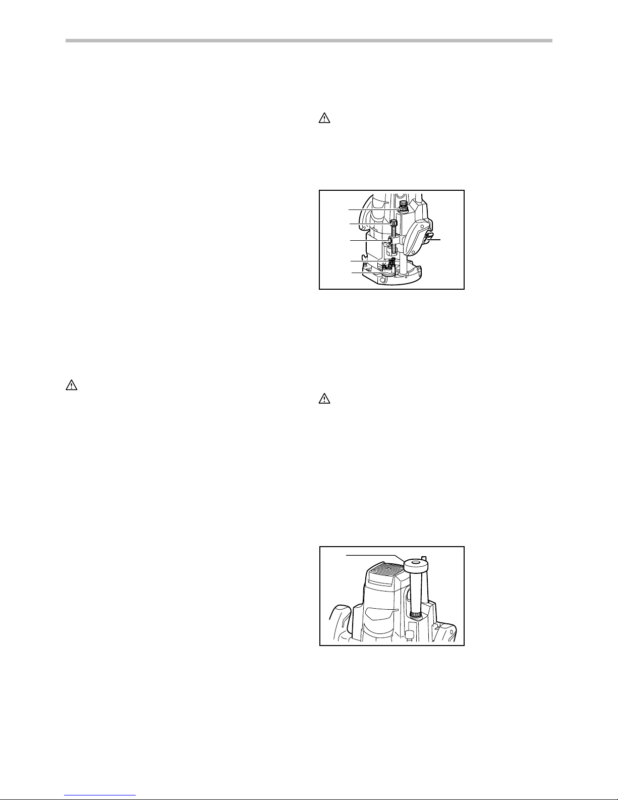
Adjusting the depth of cut
1
2
3
4
5
6
013291
Place the tool on a flat surface. Loosen the lock lever
and lower the tool body until the bit just touches the flat
surface. Press the lock lever down to lock the tool body.
While pressing the fast-feed button, move the stopper
pole up or down until the desired depth of cut is
obtained. Minute depth adjustments can be obtained by
turning the stopper pole (1.5 mm per turn).
CAUTION:
• The depth of cut should not be more than 20 mm
at a pass when cutting grooves. For extra-deep
grooving operations, make two or three passes
with progressively deeper bit settings.
Nylon nut
For tool without the knob
The upper limit of the tool body can be adjusted by
turning the nylon nut. Do not lower the nylon nut too low.
The bit will protrude dangerously.
For tool with the knob
1
013292
By turning the knob, the upper limit of the tool body can
be adjusted. When the tip of the bit is retracted more
than required in relation to the base plate surface, turn
the knob to lower the upper limit. Do not lower the knob
too low. The bit will protrude dangerously.
1. Knob
1. Nylon nut
2. Stopper pole
3. Fast-feed button
4. Adjusting hex
bolt
5. Stopper
6. Lock lever
Page 6
6
CAUTION:
• Since excessive cutting may cause overload of the
motor or difficulty in controlling the tool, the depth
of cut should not be more than 20 mm at a pass
when cutting grooves. When you wish to cut
grooves more than 20 mm deep, make several
passes with progressively deeper bit settings.
• Do not lower the knob too low. The bit will protrude
dangerously.
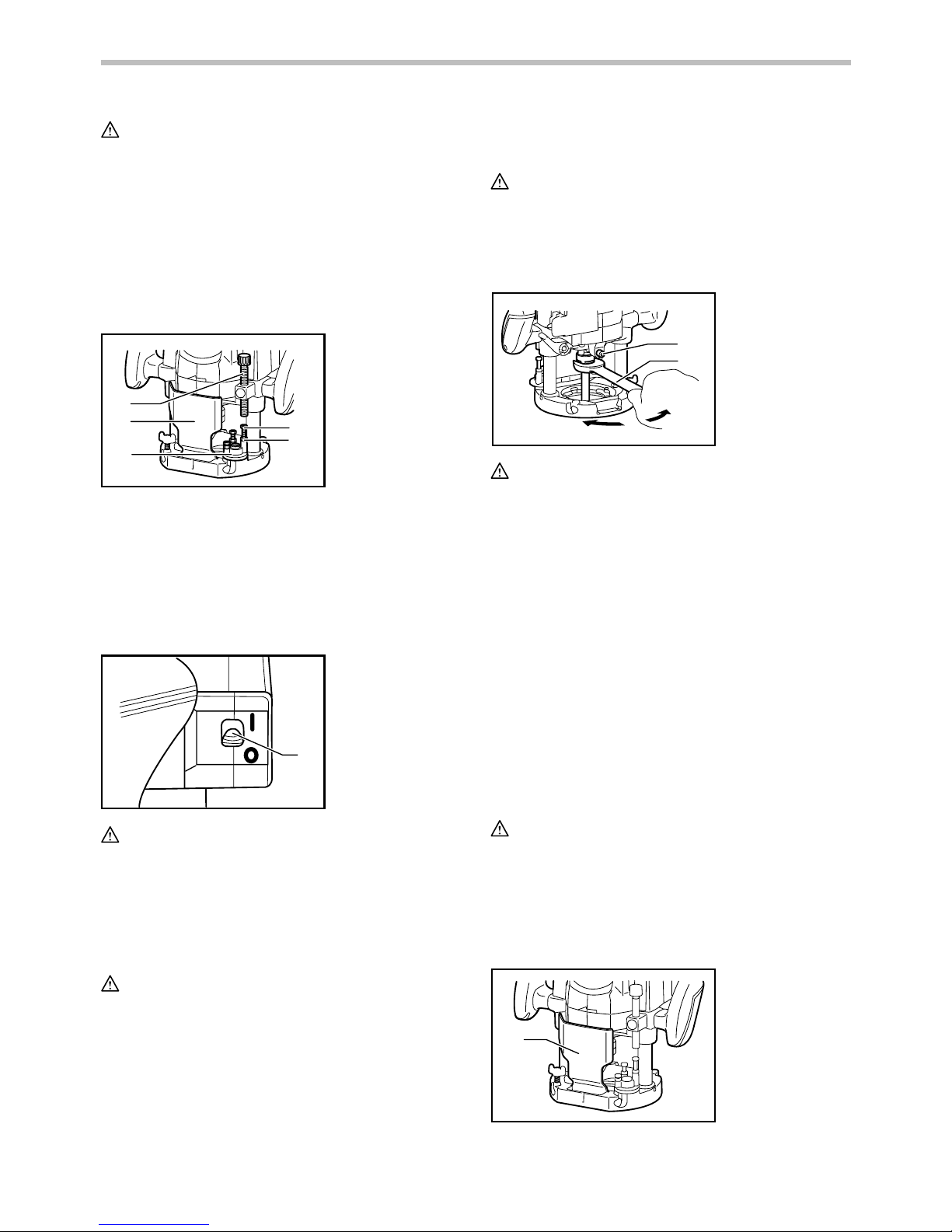
Stopper block
1
2
3
4
5
013293
As the rotary stopper has three adjusting hex bolts, you
can easily obtain three different depths of cut without
readjusting the stopper pole. To adjust the hex bolts,
loosen the hex nuts on them and turn the hex bolts.
After obtaining the desired position, tighten the hex nuts
to secure the hex bolts.
Switch action
1
013294
CAUTION:
• Before plugging in the tool, always check to see
that the tool is switched off.
• Make sure that the shaft lock is released before
the switch is turned on.
To start the tool, move the switch lever to the I position.
To stop the tool, move the switch lever to the O position.
CAUTION:
• Hold the tool firmly when turning off the tool, to
overcome the reaction.
ASSEMBLY
CAUTION:
• Always be sure that the tool is switched off and
unplugged before carrying out any work on the
tool.
Installing or removing the bit
1
2
013295
CAUTION:
• Install the bit securely. Always use only the wrench
provided with the tool. A loose or overtightened bit
can be dangerous.
• Do not tighten the collet nut without inserting a bit
or install small shank bits without using a collet
sleeve. Either can lead to breakage of the collet
cone.
Insert the bit all the way into the collet cone. Press the
shaft lock to keep the shaft stationary and use the
wrench to tighten the collet nut securely. When using
router bits with smaller shank diameter, first insert the
appropriate collet sleeve into the collet cone, then install
the bit as described above.
To remove the bit, follow the installation procedure in
reverse.
OPERATION
CAUTION:
• Before operation, always make sure that the tool
body automatically rises to the upper limit and the
bit does not protrude from the tool base when the
lock lever is loosened.
• Before operation, always make sure that the chip
deflector is installed properly.
1
013296
1. Chip deflector
1. Shaft lock
2. Wrench
1. Switch lever
1. Stopper pole
2. Chip deflector
3. Stopper
4. Adjusting hex
bolt
5. Hex nut
Page 7
7
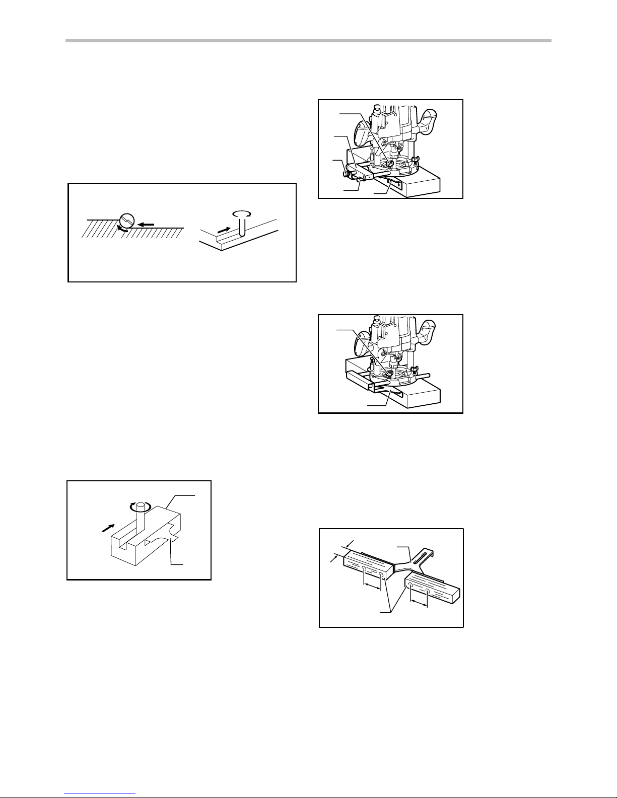
Set the tool base on the workpiece to be cut without the
bit making any contact. Then turn the tool on and wait
until the bit attains full speed. Lower the tool body and
move the tool forward over the workpiece surface,
keeping the tool base flush and advancing smoothly
until the cutting is complete.
When doing edge cutting, the workpiece surface should
be on the left side of the bit in the feed direction.
1
2
3
4
4
2
001984
NOTE:
• Moving the tool forward too fast may cause a poor
quality of cut, or damage to the bit or motor.
Moving the tool forward too slowly may burn and
mar the cut. The proper feed rate will depend on
the bit size, the kind of workpiece and depth of cut.
Before beginning the cut on the actual workpiece,
it is advisable to make a sample cut on a piece of
scrap lumber. This will show exactly how the cut
will look as well as enable you to check
dimensions.
1
2
3
4
001985
NOTE:
• When using the straight guide or the trimmer guide,
be sure to install it on the right side in the feed
direction. This will help to keep it flush with the
side of the workpiece.
Straight guide
The straight guide is effectively used for straight cuts
when chamfering or grooving.
Straight guide (Type A) (Optional accessory)
1
2
3
4
5
013299
Install the straight guide on the guide holder with the
thumb screw (B). Insert the guide holder into the holes
in the tool base and tighten the thumb screw (A). To
adjust the distance between the bit and the straight
guide, loosen the thumb screw (B) and turn the fine
adjusting screw. At the desired distance, tighten the
thumb screw (B) to secure the straight guide in place.
Straight guide (Type B) (Optional accessory)
1
2
013300
Insert the straight guide into the holes in the tool base
and tighten the thumb screw. To adjust the distance
between the bit and the straight guide, loosen the thumb
screw. At the desired distance, tighten the thumb screw
to secure the straight guide in place.
Wider straight guide of desired dimensions may be
made by using the convenient holes in the guide to bolt
on extra pieces of wood.
1
2
55 mm
55 mm
3
004931
When using a large diameter bit, attach pieces of wood
to the straight guide which have a thickness of more
than 15 mm to prevent the bit from striking the straight
guide.
When cutting, move the tool with the straight guide flush
with the side of the workpiece.
1.
More than 15 mm
2. Straight guide
3. Wood
1. Thumb screw
2. Straight guide
1. Thumb screw
(A)
2. Guide holder
3. Fine adjusting
screw
4. Thumb screw
(B)
5. Straight guide
1. Feed direction
2. Bit revolving
direction
3. Workpiece
4. Straight guide
1. Workpiece
2. Bit revolving direction
3. View from the top of the tool
4. Feed direction
Page 8
8
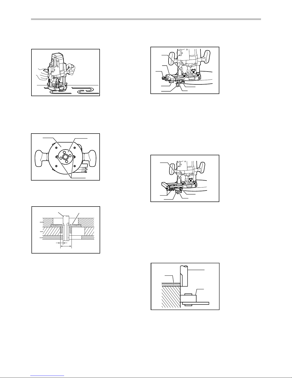
Templet guide
013301
The templet guide provides a sleeve through which the
bit passes, allowing use of the tool with templet patterns.
To install the templet guide, loosen the screws on the
tool base, insert the templet guide and then tighten the
screws.
1
2
3
013302
Secure the templet to the workpiece. Place the tool on
the templet and move the tool with the templet guide
sliding along the side of the templet.
1
2
3
4
5
6
7
003695
NOTE:
• The workpiece will be cut a slightly different size
from the templet. Allow for the distance (X)
between the bit and the outside of the templet
guide. The distance (X) can be calculated by using
the following equation:
Distance (X) = (outside diameter of the templet
guide - bit diameter) / 2
Trimmer guide
Trimming, curved cuts in veneers for furniture and the
like can be done easily with the trimmer guide. The
guide roller rides the curve and assures a fine cut.
Trimmer guide (Type A) (Optional accessory)
1
2
3
4
5
6
7
013305
Install the trimmer guide on the guide holder with the
thumb screw (B). Insert the guide holder into the holes
in the tool base and tighten the thumb screw (A). To
adjust the distance between the bit and the trimmer
guide, loosen the thumb screw (B) and turn the fine
adjusting screw. When adjusting the guide roller up or
down, loosen the thumb screw (C). After adjusting,
tighten all the thumb screws securely.
Trimmer guide (Type B) (Optional accessory)
1
2
3
4
5
013306
Install the trimmer guide on the straight guide with the
thumb screws (B). Insert the straight guide into the
holes in the tool base and tighten the thumb screw (A).
To adjust the distance between the bit and the trimmer
guide, loosen the thumb screws (B). When adjusting the
guide roller up or down, loosen the thumb screw (C).
After adjusting, tighten all the thumb screws securely.
When cutting, move the tool with the guide roller riding
the side of the workpiece.
3
1
2
003701
1. Bit
2. Guide roller
3. Workpiece
1. Thumb screw
(A)
2. Thumb screws
(B)
3. Thumb screw
(C)
4. Guide roller
5. Trimmer guide
1.
Thumb screw (A)
2. Guide holder
3. Fine adjusting
screw
4.
Thumb screw (B)
5.
Thumb screw (C)
6. Trimmer guide
7. Guide roller
1. Bit
2. Base
3. Templet
4. Workpiece
5. Distance (X)
6. Outside
diameter of the
templet guide
7. Templet guide
1. Templet guide
2. Screws
3. Base plate
Page 9
9
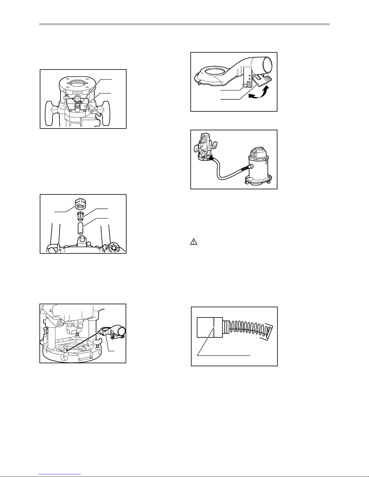
Dust cover (For tool with the knob) (optional
accessory)
1
2
013307
Dust cover prevents sawdust from being drawn into the
tool in the inverted position.
Install the dust cover as illustrated when using the tool
with a router stand available in the market.
Remove it when using the tool in the normal position.
Spacer (For tool with the knob) (Optional
accessory)
1
2
3
005114
The spacer prevents the router bit from dropping into
the chuck when replacing the bit in the inverted position.
Insert the spacer as illustrated when using the tool with
a router stand available in the market.
Dust extraction (Optional accessory)
1
013308
Use the vacuum head for dust extraction. To Install the
vacuum head, raise the lock lever on it. Place the
vacuum head on the tool base so that its top will be
caught in the hook on the tool base. Insert the supports
on the vacuum head into the hooks on the front of the
tool base.
Push down the lock lever onto the tool base.
1
2
004940
Then connect a vacuum cleaner to the vacuum head.
013309
To remove the vacuum head, raise the lock lever. Pull
the vacuum head out of the tool base while holding the
supports between thumb and finger.
MAINTENANCE
CAUTION:
• Always be sure that the tool is switched off and
unplugged before attempting to perform inspection
or maintenance.
• Never use gasoline, benzine, thinner, alcohol or
the like. Discoloration, deformation or cracks may
result.
Replacing carbon brushes
1
001145
Remove and check the carbon brushes regularly.
Replace when they wear down to the limit mark. Keep
the carbon brushes clean and free to slip in the holders.
Both carbon brushes should be replaced at the same
time. Use only identical carbon brushes.
1. Limit mark
1. Support
2. Lock lever
1. Vacuum head
1. Collet nut
2. Collet cone
3. Spacer
1. Screw
2. Dust cover
Page 10
10
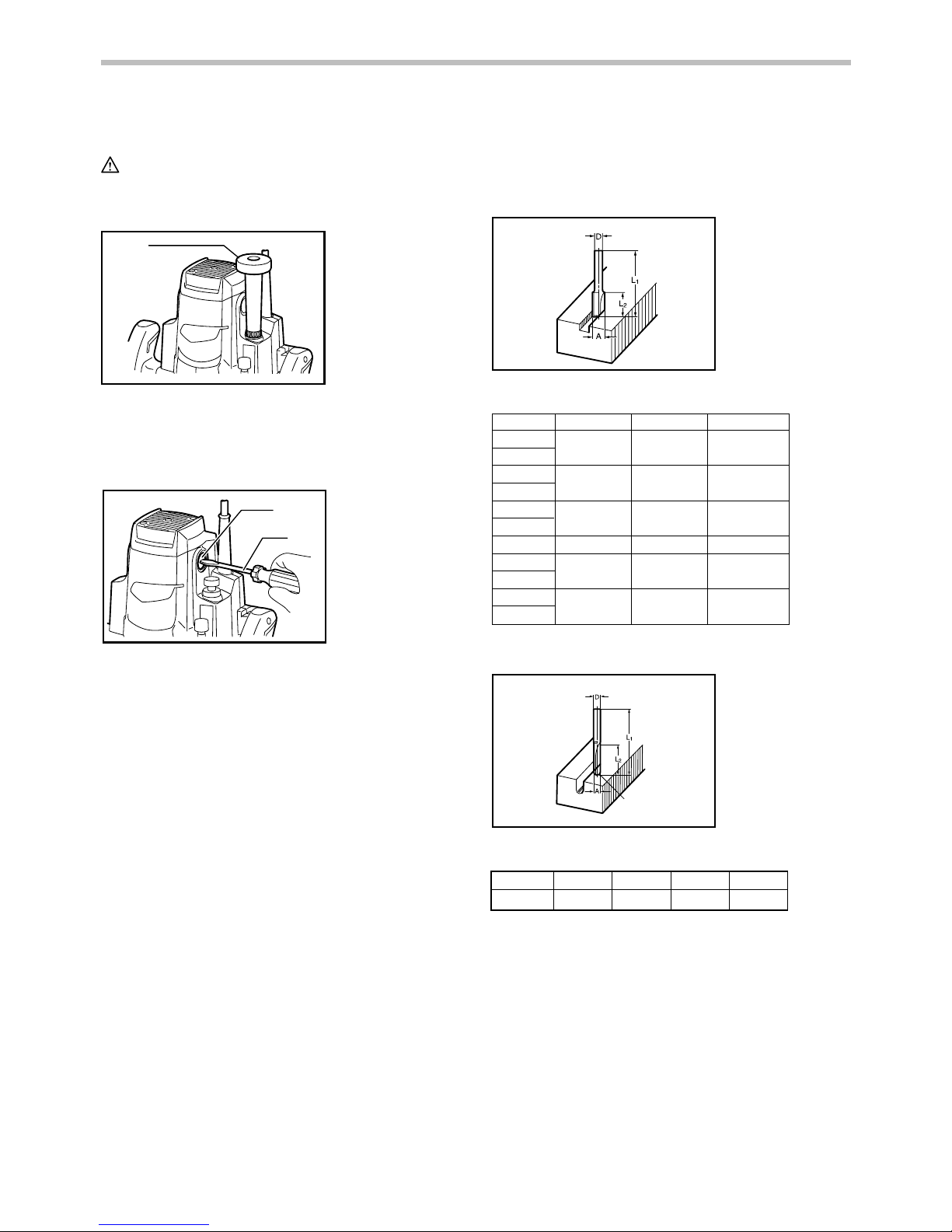
For tool with the knob
CAUTION:
• Be sure to re-install the knob after inserting new
carbon brush.
1
013310
Release the lock lever and remove the knob by turning
it counterclockwise. The compression spring will come
out of the knob, so be careful not to lose the
compression spring.
1
2
013311
Use a screwdriver to remove the brush holder caps.
Take out the worn carbon brushes, insert the new ones
and secure the brush holder caps.
To maintain product SAFETY and RELIABILITY, repairs,
any other maintenance or adjustment should be
performed by Makita Authorized Service Centers,
always using Makita replacement parts.
OPTIONAL ACCESSORIES
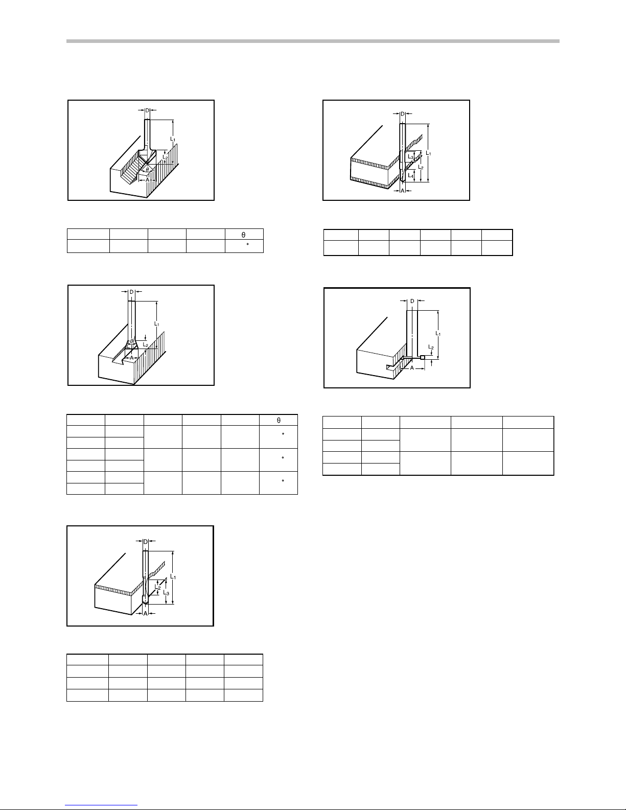
Router bits
Straight bit
005116
mm
DA L 1 L 2
6
1/4"
8 8 60 25
6
1/4"
6
1/4"
65018
85018
20 50 15
1/2"
12
1/2"
12
12 60 30
10 60 25
006452
"U"Grooving bit
R
005117
mm
DAL 1L 2R
6 6 50 18 3
006453
1. Brush holder
cap
2. Screwdriver
1. Knob
Page 11
11
"V"Grooving bit
005118
mm
DAL 1L 2
1/4"
20
50 15
90
006454
Dovetail bit
005119
mm
DAL 1L 2
8
3/8"
8
3/8"
8
3/8"
12 50 9
14.5 55 14.5
14.5 55
10
30
23
35
15S
15SE
15L
15LE
12
12E
006455
Drill point flush trimming bit
005120
mm
D A L 1 L 2 L 3
12
8
6
660
18 28
8
60
20
35
12
60
20 35
006456
Drill point double flush trimming bit
005121
mm
D A L 1 L 2 L 3
6 6 70 40 12
L 4
14
006457
Slotting cutter
005122
mm
DL 1 L 2 A
55 6 30
612
6E 1/2"
312
3E 1/2"
55 3
30
006458
Page 12
12
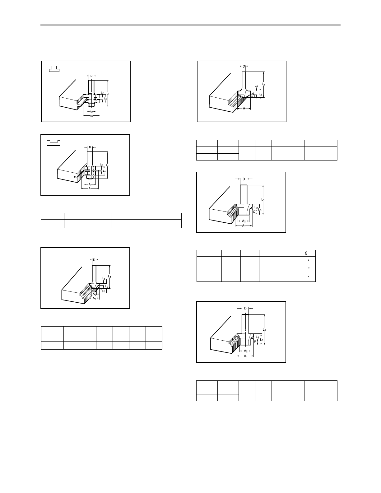
Board-jointing bit
005123
005124
mm
D A 1 A 2 L 1 L 2 L 3
12 2038 27 61 4
006459
Corner rounding bit
005125
mm
D A 1 L 1 L 2 L 3
6
6
20
45 10 4
25
A 2
8
9
48 13
5
R
4
8
006460
Chamfering bit
005126
mm
DA 1 L 1L 2 C
30 12
30E 1/2"
30
A 2
20 55 12
L 3
20
4
006461
005127
mm
D A L 1 L 2 L 3
6
6
6
20 49
14
2
20
50
13
5
23
46
11
6
30
45
60
006462
Beading bit
005128
mm
DA 1 L 1L 2 R
4R 12
4RE 1/2"
30
A 2
20 55 12
L 3
20
4
006463
Page 13
13
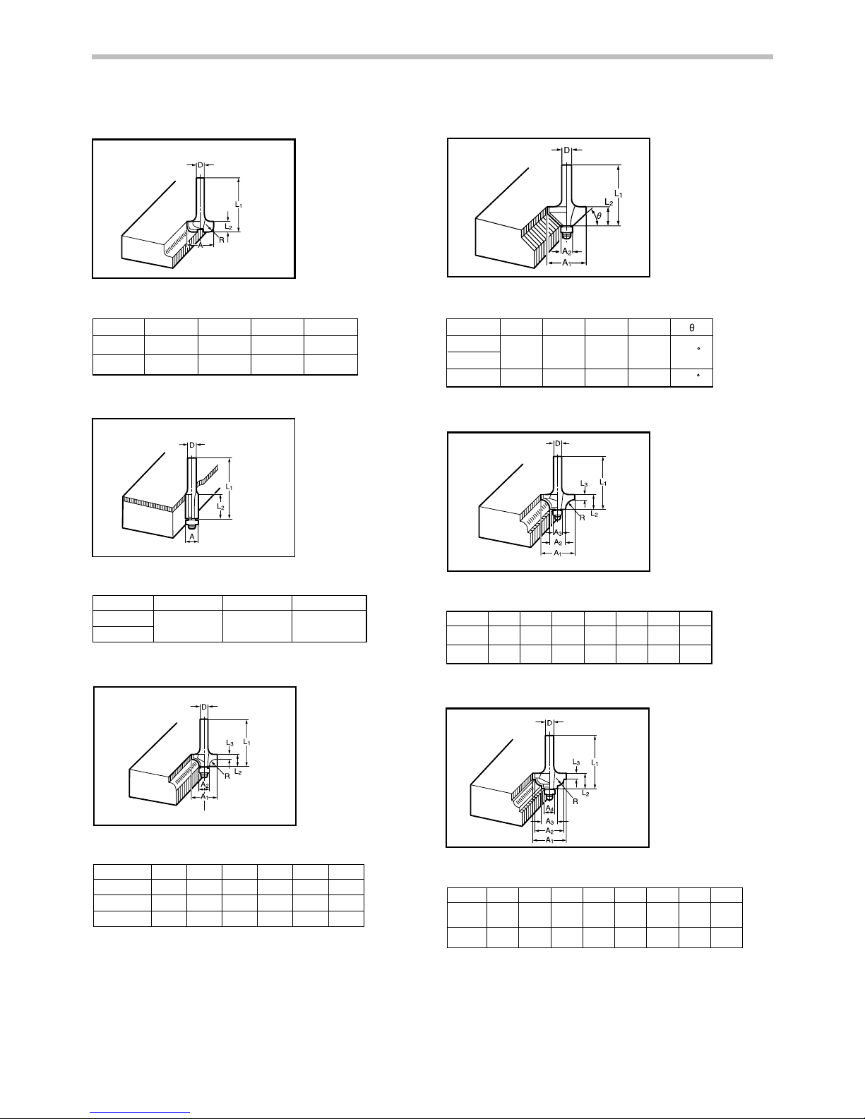
Cove beading bit
005129
mm
DAL 1L 2R
20
43
8
4
6
6
25
48
13
8
006464
Ball bearing flush trimming bit
005130
mm
DA L 1 L 2
6
1/4"
10 50 20
006465
Ball bearing corner rounding bit
005131
mm
D A 1 A 2 L 1 L 2 L 3 R
6
6
1/4"
3.5
3
3.5
6
21
40
10
15
8
37
7
21
8
8
40
10 3.5
6
006466
Ball bearing chamfering bit
005132
mm
D A 1 L 1
26 42
6
1/4"
45
60
6
20
A 2
8
8
41
L 2
12
11
006467
Ball bearing beading bit
005133
mm
D A 1 A 2 A 3 L 1 L 2 L 3 R
6
6
5.5
4
4.5
10
12
7
26
12
8
42
20
12
8
40
006468
Ball bearing cove beading bit
005134
mm
D A 1 A 2 A 4 L 1 L 2 L 3 R
6
6
5.5 3
5
10
12
5
26
22
8
42
20 18
8
A 3
12
12
40
006469
Page 14
14
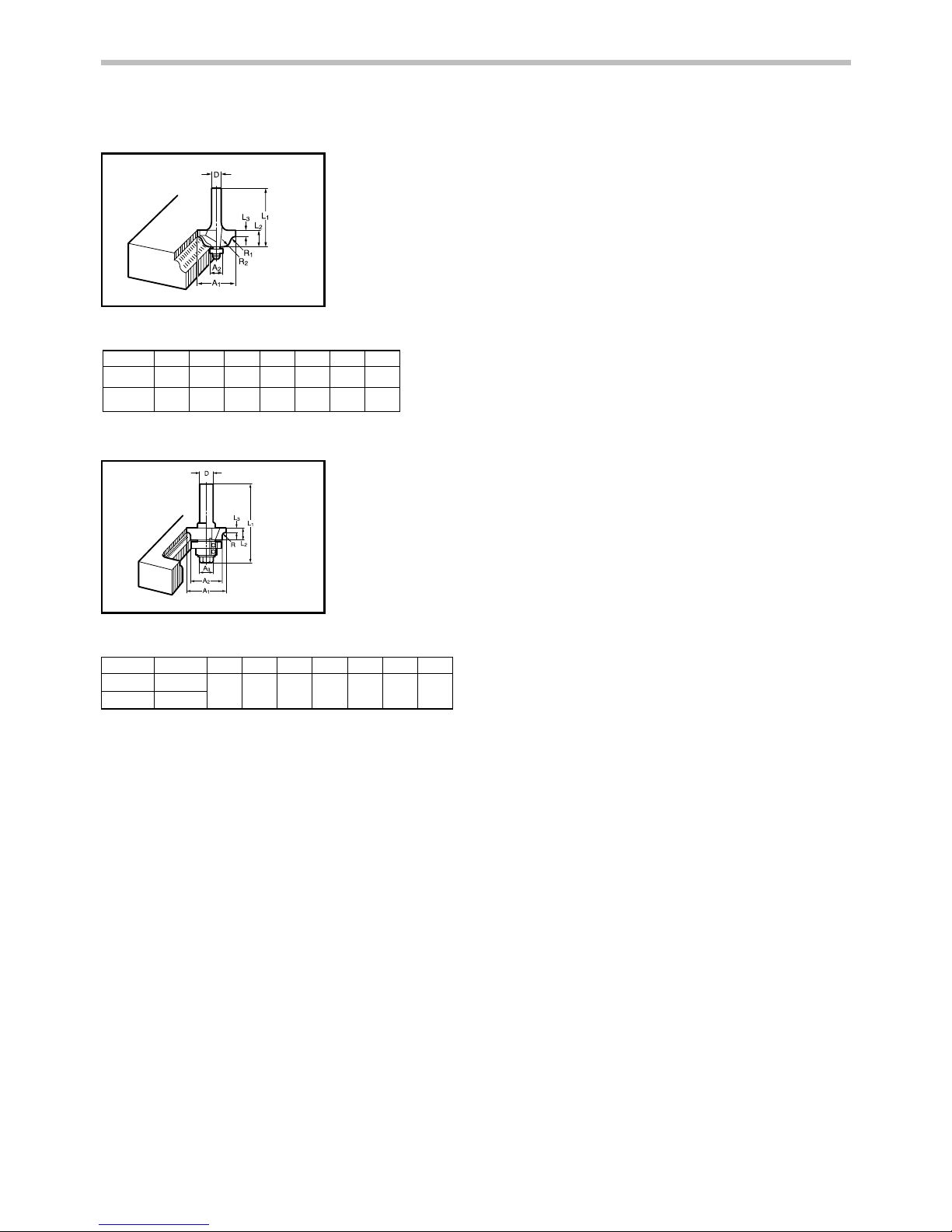
Ball bearing roman ogee bit
005135
mm
D A 1 A 2 L 1 L 2 L 3 R1 R2
6
6
2.5
4.5
3
4.5
4.5
6
26
8
42
12
20 8
40
10
006470
Double ball bearing round corner bit
005136
mm
DA 1 L 1L 2 R
3R 12
3RE 1/2"
35
A 227A 3
19 70 11
L 3
3.5
3
006471
Page 15

15
Page 16

16
Makita Corporation
Anjo, Aichi, Japan
www.makita.com
885173A224
 Loading...