

Page 1

PHM.30
Pocket Hole Machine
Attention: Read this manual before using your machine.
Page 2
1. INSTRUCTION MANUAL
1.1. Please read all instructions prior to
attempting to use the PHM.30.
The images in this manual are illustrative and are
meant to demonstrate the correct operation of your
product.
Instruction manual images may vary slightly
Note:
from actual product.
CAUTION:
replacement
When servicing, use only identical
parts.
1.2. Specifications:
Power: 2,400 W
Wood Thickness Limit: 1/2” - 1-9/16”
Amperage: 19 A
Drill: High-speed steel 9/64”
Cutter: 1/4”
Volts: 127 V
Air Pressure: 6 bar (87 Psi)
Dimensions: 25-5/8“ x 30” x 42-1/2“
Net Weight: 165.4 Lbs (75 Kg)
Gross Weight: 243.6 Lbs (110.50 Kg)
CBM: 760 x 840 x 1270 mm
(29-59/64” x 33-5/64” x 50”)
2. GROUNDING INSTRUCTIONS
2.1. THIS PHM.30 HOLE MACHINE MUST BE
CONNECTED TO A GROUNDED WIRING SYSTEM or
to a system with an equipment-grounding conductor. In
the event of a malfunction, grounding provides a path of
least resistance for electric current to reduce the risk of
electric shock. This PHM.30 hole machine is equipped
with an electric cord including an equipment-grounding
conductor and a grounding plug. The plug must be
connected into a matching outlet provided. If it will not fit
the outlet; have the proper outlet installed by a qualified
professional. Improper connection of the
equipment-grounding conductor can result in a risk of
electric shock and/ or malfunction. If repair or
replacement of the electric cord or plug is necessary, do
not connect the equipment-grounding conductor to a live
terminal. Check with a qualified professional if the
grounding instructions are not completely understood or if
to whether the PHM.30 hole machine is properly
grounded. Use only 3-wire extension cords that have
3-prong grounding plugs and 3-pole receptacles that
accept the PHM.30 hole machine’s plug.
2.2. REPAIR OR REPLACE A DAMAGED OR WORN
CORD IMMEDIATELY. When servicing use only identical
replacement parts.
2.3. USE PROPER EXTENSION CORD. Make sure your
extension cord is in good condition. When using an
extension cord, be sure to use one properly equipped to
carry the current your PHM.30 hole machine will draw.
An undersized cord will cause a drop in line voltage
resulting in loss of power and overheating. For cord
length of up to 50 feet, use a cord of 14 gauge. For a
cord length of 50 to 100 feet, use a cord of 12 gauge. A
cord length over 100 feet is not recommended. If in
doubt, use the next heavier gauge. Smaller the gauge
number, heavier the cord.
2.4. IMPORTANT: Do not use an extension cord with
length above 20 meters.
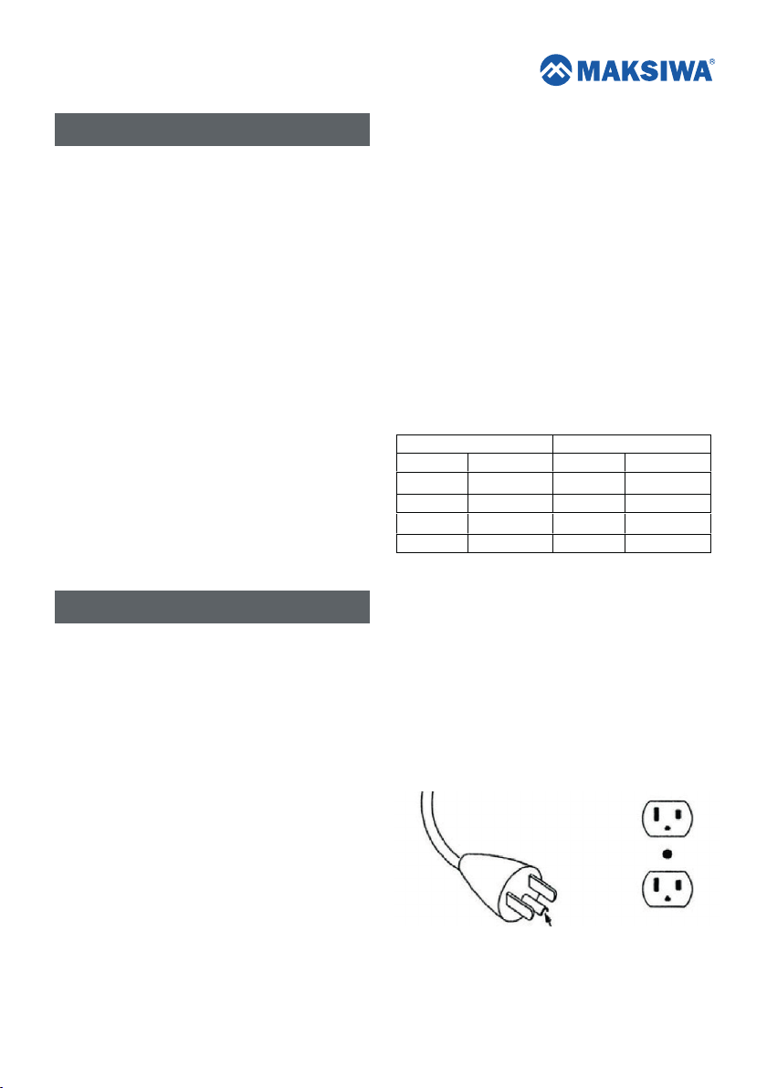
Cable 2 wires Cable 3 wires
Ø (mm²) Amperage Ø (mm²) Amperage
0,5 9 0,5 8
1,0 13 1,0 12
1,5 16,5 1,5 15
2,5 23 2,5 20
2.5. The PHM.30 hole machine has a grounding plug
similar to the plug illustrated in Fig. 1. Make sure the
PHM.30 hole machine is connected to an outlet having
the same configuration as the plug. No adapter is
available or should be used with this PHM.30 hole
machine. If the machine must be reconnected for use on a
different type of electric circuit, the reconnection should
be made by a qualified professional; and after
reconnection, the PHM.30 hole machine should comply
with all local codes and ordinances.
Fig.1
2
Page 3
3. ASSEMBLY
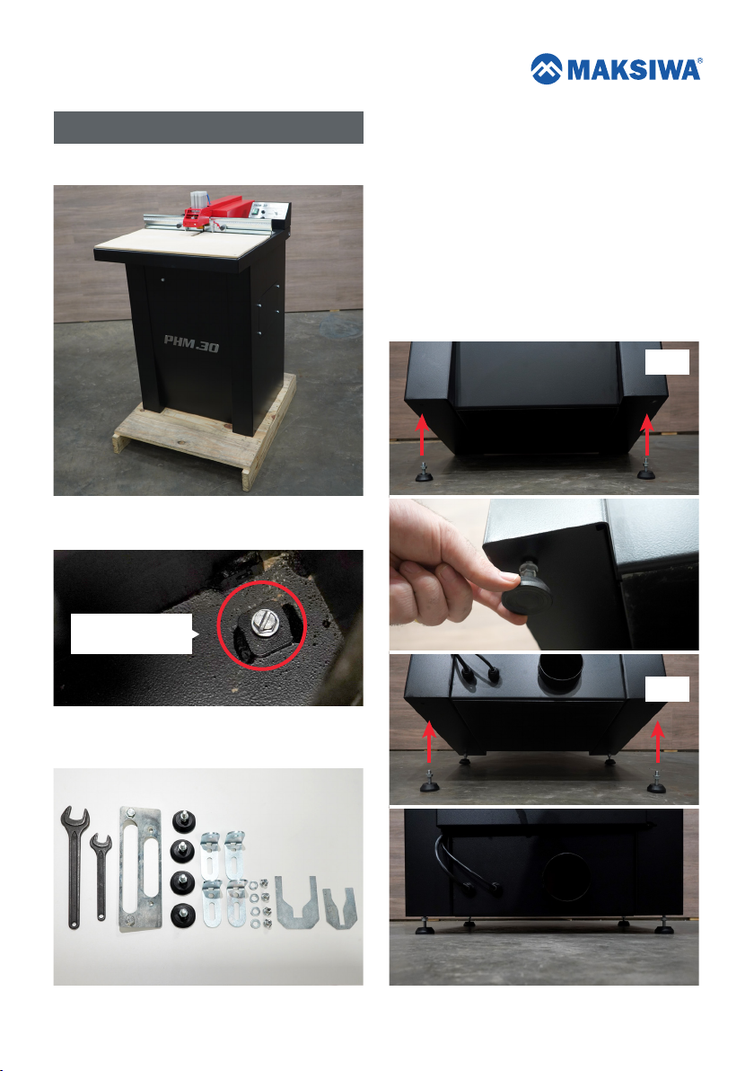
3.1. You will receive your machine palleted.
3.2. Remove the screws that secure the machine to the
pallet inside machine.
Screws that secure
the machine.
1 - Wrench 15/16” (24 mm)
2 - Wrench 43/64” (17 mm)
3 - Template for adjusting the router
4 - Feet
5 - Base bolt
6 - Screw and washer
7 - Template for adjusting the 1 HP router
8 - Template for adjusting the 2.25 HP router
3.4. Place the adjustable feet and position the machine
upright on the floor. Set the positioning of the feet until the
machine is level, then tighten the nuts next to the plate, as
shown below:
Front
3.3. Remove the machine from the pallet with all included
parts and accessories.
1 2 3 4 5 6 87
Back
3
Page 4
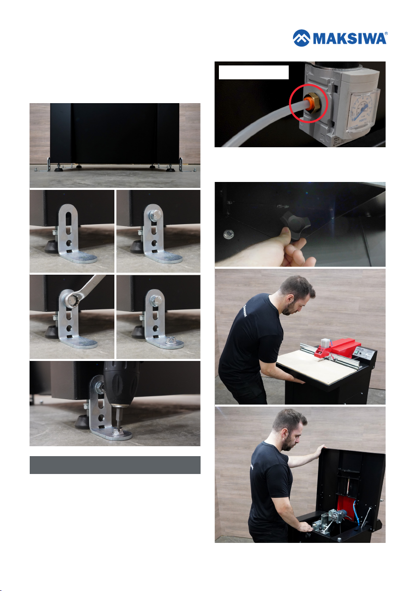
3.5. It is possible to anchor the machine on the floor. To
do this, align the base screw on the floor and secure it to
the machine and the floor. We recommend bolting the
machine mainly for use on large workpieces.
Connector and Hose
4.2. At the front of the machine, unlock the top and lock
it to check for roughages. Make sure the handle is locked.
4. ADJUSTMENTS
4.1. Choose a 1/4” hose with a pressure of 6 bar (90
psi) and fit the connector behind the machine.
4.1.1. ATTENTION: Use filtered compressed air.
4
Page 5
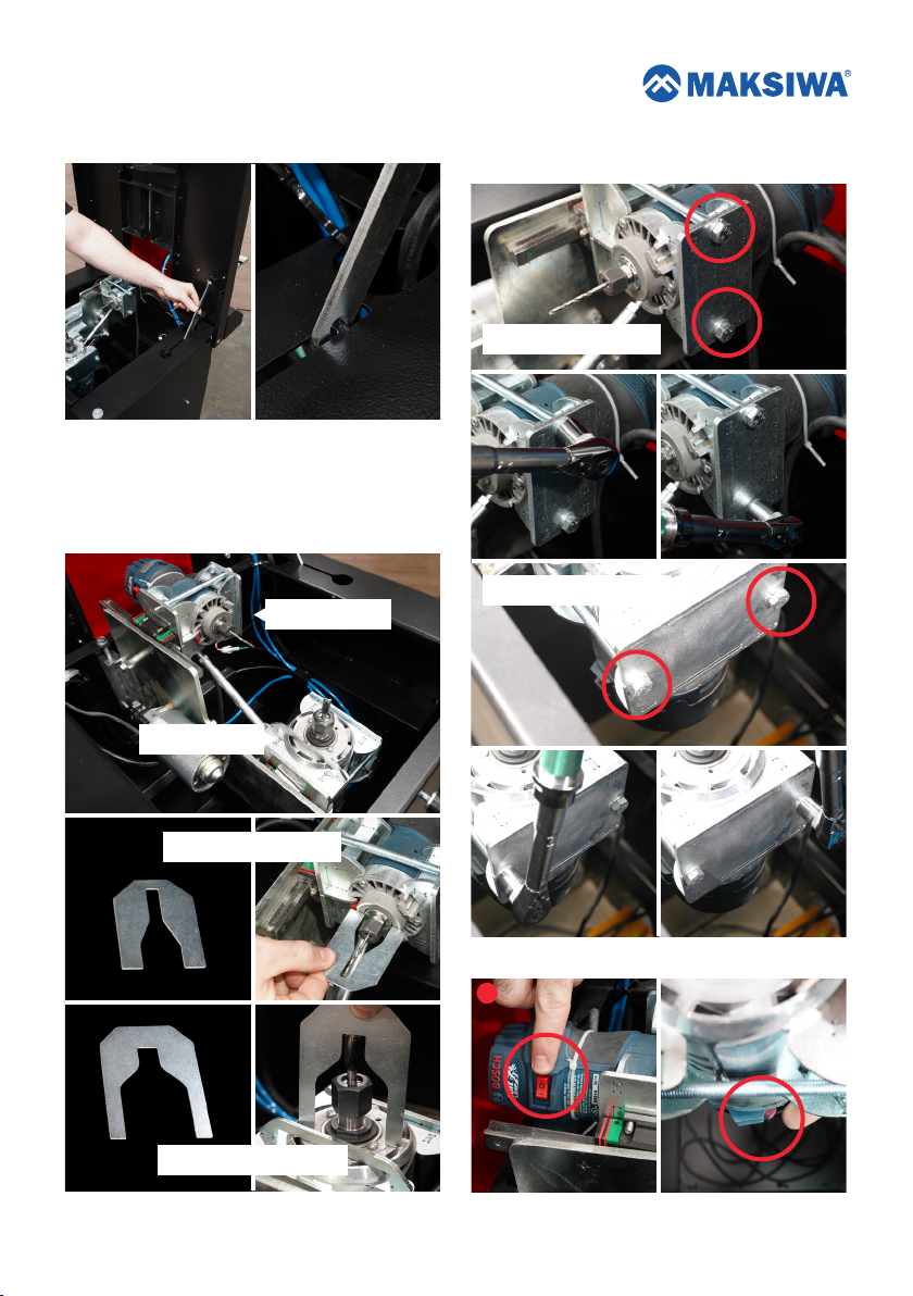
4.2.1. Be sure to lock the table. 4.4. Make sure the routers are securely attached.
4.3. With the table top open and locked, check that the
router bits are at the correct height as per the templates.
4.3.1. Note: To change the height of the drills, check
the router manual.
1 HP Router
2.25 HP Router
Maximum torque must be 3.0 Nm.
1 HP Router adjustment
2.25 HP Router adjustment
1 HP Router adjustment
2.25 HP Router adjustment
4.5. Make sure the routers are on.
1
5
Page 6
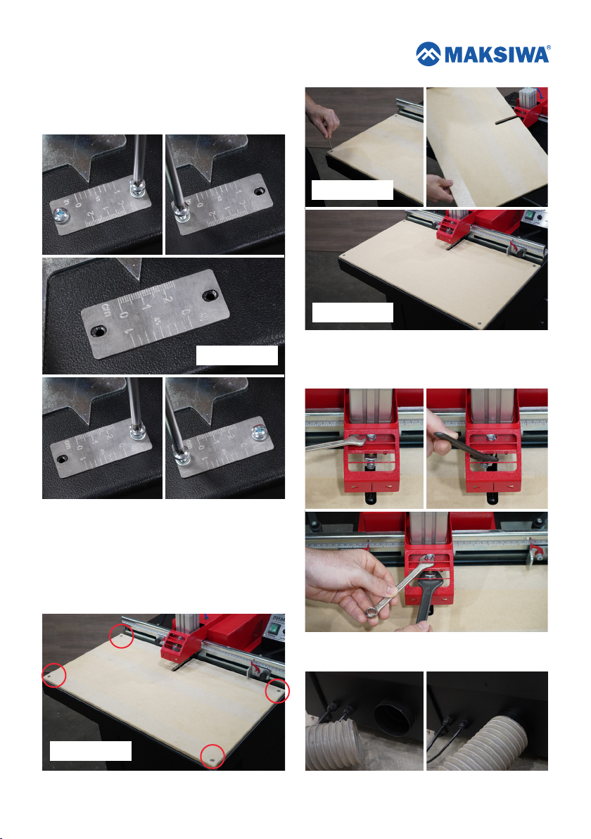
4.6. Choose the value unit (centimeters or inches) of the
depth of cut scale. To change the position of the scale,
simply unscrew, reverse position, and screw again.
Inverted position
Smooth table
Inverted position
4.7. The table has two sides for use. One smooth side
and another side with sandpaper. Choose the side of the
table you want to use. To do this, simply unscrew the
table, turn it over and screw again.
4.7.1. When Working with coated wood use smooth
side. When working with non-coated wood use abrasive
side.
Sand table
4.8. To adjust the laser guide, loosen the screw and align
the laser guide left or right. Once the Laser is centered,
tighten the screw.
4.9. Connect a Dust Collector (minimum 1 HP) to the
machine. The port diameter is 4”.
6
Page 7
5. OPERATIONS
5.1. The operations made by the PHM.30 hole machine,
as well as any other machine, can pose risks to the
operator if the instructions in this section are not taken into
account. These instructions are written with the
understanding that the operator has the knowledge and
skills necessary to operate this machine. If at anytime
you're having difficulty performing any operation, stop
using the machine. If you are an inexperienced operator,
we recommend that you read books, technical papers, or
seek training from an experienced operator before
performing any unfamiliar operation. The machine must
operate with all the protections and security systems that
comes standard.
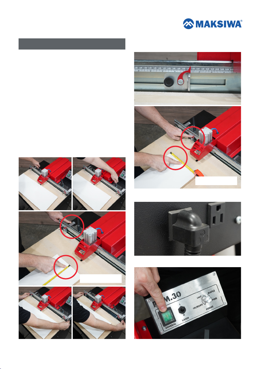
5.2. Loosen the depth scale knobs and choose the
distance you want from the base of the workpiece to the
beginning of the tear. After that tighten the knobs.
5.3. Choose the size you want from the tear, to the side
of the workpiece. Then tighten the knobs.
Same measurement
5.4. Plug in the machine.
Same measurement
5.5. Turn GENERAL switch ON.
7
Page 8
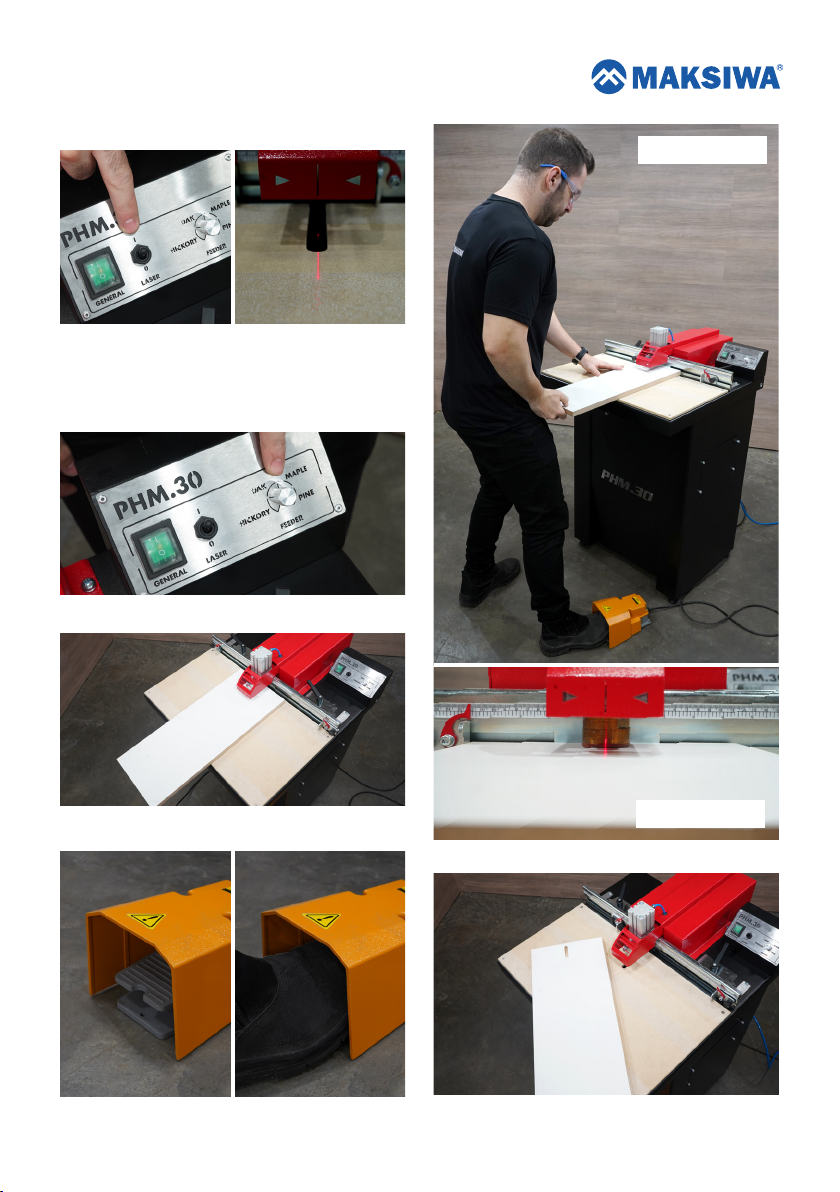
5.6. Turn LASER switch ON.
5.7. Set the Feeder to the to the type of wood you are
working with.
5.7.1. The denser the wood, the slower the feeder must
be..
5.8. Position the workpiece.
Operator Position
5.9. Press the pedal until the operating cycle is complete.
8
Operation detail
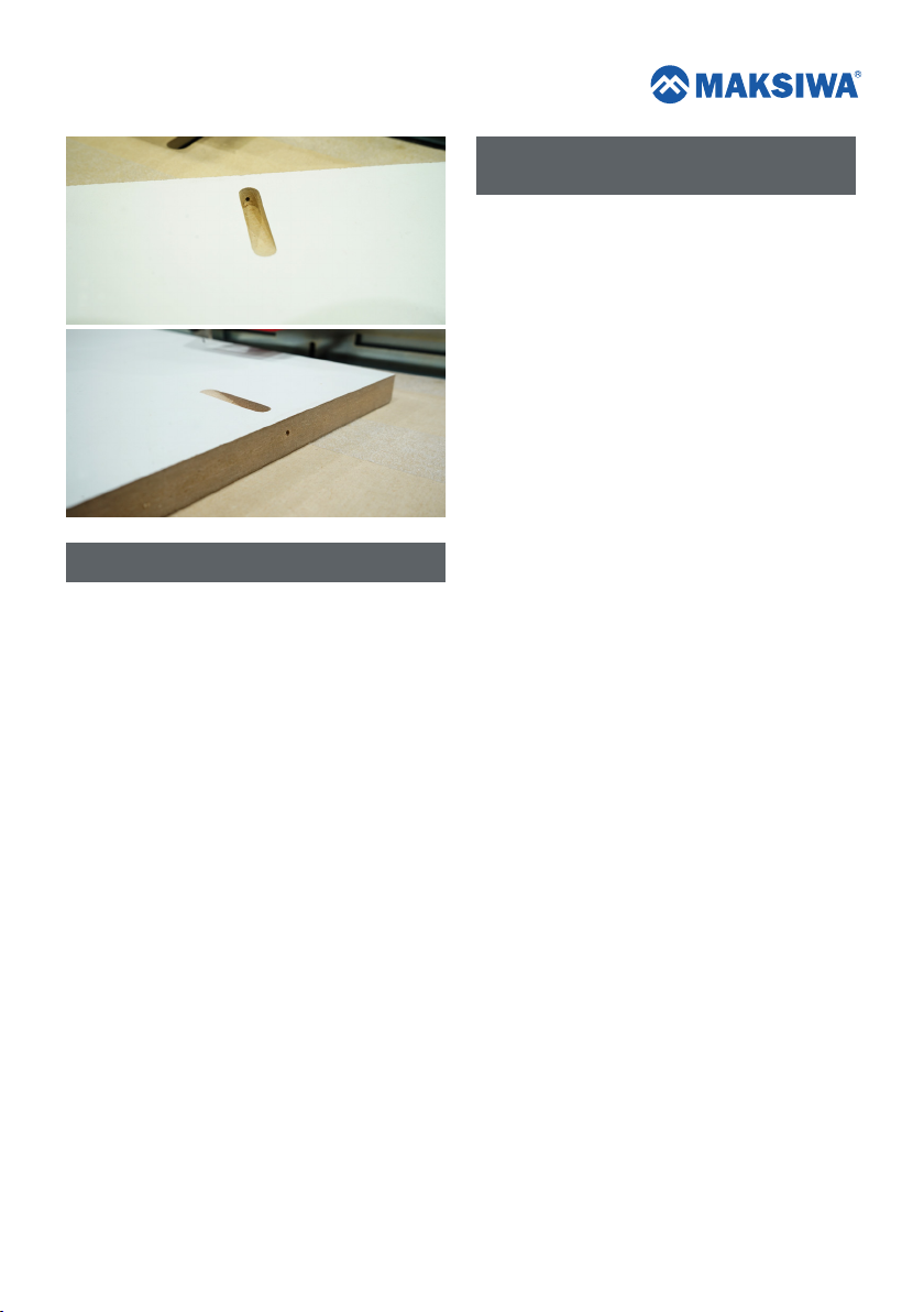
5.10. Final result.
Page 9
7. GENERAL SAFETY INSTRUCTIONS
FOR ALL EQUIPMENT
7.1. Keep a clean work surface. Cluttered areas and
work surfaces can contribute to accidents.
7.2. Do not use the PHM.30 hole machine in hazardous
environments. Do not use machine in damp or wet
locations or exposed to rain.
7.3. Keep work area well-lit.
7.4. Keep children away. Visitors should be kept at a
safe distance from work area.
7.5. Do not overreach on the equipment. Maintain
balance and keep your feet in a comfortable position at
all times.
6. MAINTENANCE
6.1. IMPORTANT: All maintenance or repairs of the
machine should be done with the machine OFF and
unplugged from the outlet to prevent accidental
electrocution or a short circuit.
6.2. GENERAL:
Periodic maintenance on your PHM.30 hole machine will
ensure optimum performance. Make it a habit to inspect
your PHM.30 hole machine every time you use it. This
section covers the service adjustments or common
procedures that may need to be made during the life of
your machine. Verify if the following conditions for repair
or replacement are needed:
• Loose screws.
• Switches or buttons damaged.
• Keep drills and cutters sharp.
• Keep the height of the routers aligned.
• Make sure the routers are securely attached.
• Check, cables, plugs and sockets for wear or Damage.
• Transmission chain damaged.
• Any other condition that could adversely affect the safe
operation of the equipment.
7.6. Keep all tools in order. Keep tools sharp and clean
for better and safer performance. Follow the instructions
for lubricating and changing accessories.
7.7. Unplug the machine before servicing or changing
accessories such as scissors, cutters etc.
7.8. Reduce the risk of unintentional starting. Ensure that
the switch is in the “OFF” position before connecting the
plug wires.
7.9. Use recommended accessories. See the instruction
manual for a list of recommended accessories. Improper
use of accessories may cause risk of injury to person
(s).
7.10. Never step or stand on the machine. A serious
accident may occur if the machine is dented or if parts are
accidentally touched.
7.11. Check for damaged parts, before continuing the
use of the PHM.30 hole machine, a guard or other part
that is damaged should be examined carefully to
determine weather its ability to perform is function
properly has been affected. Check the alignment of
moving parts, wear of parts, mounting and any other
condition that may affect its operation. If any part is
damaged and must be replaced do so immediately. Do
not attempt to repair/replace any parts unless the
machine is off and unplugged.
9
Page 10

7.12. Never leave a running tool unattended.
7.13. The motor of this machine can emit sparks, and
react with flammable gases.
7.27. Do not attempt to operate the machine in another
voltage beyond designated.
7.28. Do not use other tools than recommended.
7.14. CAUTION: FAILURE TO ADHERE TO THESE
WARNINGS MAY RESULT IN PERSONAL INJURY AND
SERIOUS DAMAGE TO THE MACHINE.
7.15. ALWAYS USE PROPER PROTECTIVE
EQUIPMENTS TO OPERATE THIS MACHINE.
7.16. Always use safety glasses. Also use face or dust
mask if cutting operation is dusty. Everyday eyeglasses
only have impact resistant lenses, they are NOT safety
glasses.
7.17. Keep guards in place and working order.
7.18. Protect the electric power supply line with at least
a 20 amp fuse or a circuit breaker switch.
7.19. Make sure that the router is turning in the proper
direction.
7.20. Make sure that the knobs and screws are properly
tightened and secure before starting any operation.
7.21. Keep tool clean and in good working condition.
7.22. It is recommended wearing shoes with non-slip
soles. Use protection for hair in order to avoid becoming
caught in moving parts.
7.23. Use appropriate equipment. Do not wear loose
clothing, gloves, chains, rings, bracelets or other
accessories that could become caught in moving parts.
7.24. Keep vents free of debris.
7.25. Keep hands away from moving or sharp parts.
7.26. In case the wood is to long, support the ends on
the sides of the machine to prevent warping.
7.29. Do not apply lubricant to the tools during use.
7.30. Do not operate without all parts of the machine
properly assembled.
7.31. Do not use lubricants or cleaners (particularly
sprays and aerosols) in the vicinity of the plastic guard.
The polycarbonate material used in the guard is sensitive
to certain chemicals.
7.32. WARNING: Some dust created by the act of
sanding, cutting, grinding, drilling and other
construction-related activities contains chemicals that can
cause cancer, birth defects or other reproductive harm.
Some examples of these products are: Leadbased paint;
crystal silica bricks, concrete and other masonry products;
and arsenic and chromium from chemically treated wood.
7.33. CAUTION: Do not connect the unit to the power
outlet until all instructions have been read and
understood. Always tighten the adjustment tabs before
using the machine. Think: "How can I prevent accidents?".
7.34. ELECTRICAL CONNECTION
The PHM.30 hole machine has 1-phase 127V motor. To
avoid burning risk, check the voltage of your outlet before
starting the machine. If necessary, make the change to
your power source with the help of a qualified
professional.
7.34.1. Ensure that your power supply is in accordance
with that designated on the board. A 10%
decrease/increase in voltage will cause loss of power or
overheating. All machines are tested at the factory. If this
machine does not turn on, check the electricity supply.
7.34.2. Check the compatibility of your outlet and plug
in the machine.
7.34.3. Do not do patches and adaptations.
7.34.4. To avoid electrical shock and damage to the
equipment always ground the machine.
10
Page 11

7.35. FAMILIARIZATION
Place the machine on a smooth, flat surface. Check the
pictures and watch the descriptions in this manual to
familiarize yourself with all parts and locations.
8. WARRANTY TERMS
8.1. Maksiwa assures the owner of his equipment,
identified by the date of issue of the purchase invoice, a
warranty of two (2) years, as follows:
8.2. The warranty period begins on the date of the
commercial invoice.
8.3. Within the warranty period, the hand labor and the
components replaced by manufacturing defect will be
provided for free as long as duly proved by Maksiwa.
8.4. Third-party manufacturing equipment that makes up
the Maksiwa equipment (such as motors, electrical
equipment, belts etc.) are subject to the terms and
conditions of warranty of their respective manufacturers.
8.5. In the case of a warranty exchange, please return
the defective part to the manufacturer urgently.
8.6. Costs and risks of transport will be assumed by the
machine owner.
8.12. Even under warranty, you may lose its validity as
follows:
a) Application of non-original components;
b) Alteration of its original features;
c) Lack of proper maintenance;
d) Improper use of the equipment;
e) Change in equipment or electronic connections;
f) Damage caused by mechanical shock or exposure
to unsuitable conditions (humidity, salt spray, corrosive
agents, etc.);
g) Damage caused by bad weather (floods, flooding,
lightning, power outages etc.).
For any further assistance, contact us at:
Tel: +1 (844) 319-6594
E-mail: [email protected]
8.7. Equipment installation expenses and workplace
adaptations are due to the machine owner.
8.8. When you notice any defect or malfunction when
receiving the equipment, get in touch immediately with the
manufacturer or dealer. Do not turn it on.
8.9. Not included in this warranty are technical visits
aimed at cleaning or adjustments caused by wear,
resulting from normal use of the equipment.
8.10. The warranty does not cover problems caused by
mistreatment, carelessness, misuse of the functions
designed for this equipment in this manual, as well as
poorly executed operations by untrained operators.
8.11. Maksiwa is not responsible for lost productivity,
direct or indirect damages caused to the owner of the
equipment or to third parties, or any other expense,
including lost profits.
11
Page 12
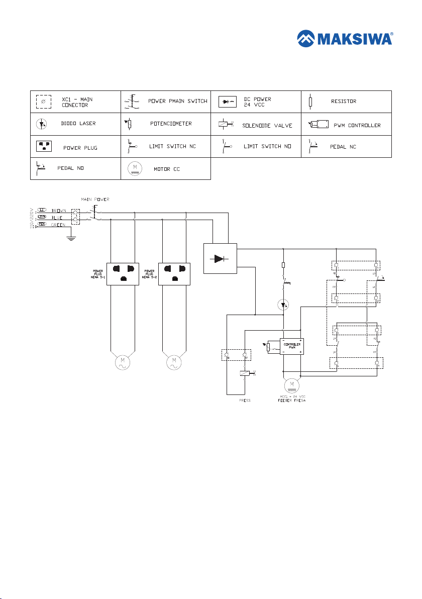
9. ENABLE HEAT AND CONTROL
0 1
XC1
0 1
BK - 1,5 mm²
BK - 1,5 mm²
BK - 1,0 mm²
BK - 1,0 mm²
BK - 0,5 mm²
BK - 0,5 mm²
POWER SUPPLY -
24V - 3,2 A
24+
R1
24-
1.2 K x 1/8W
FC1
XC1
PD1
12
1
ROUTER CANAL
DL1
1
XC1
MAK-08
FC1
XC1
XC1
PD1
XC1
Page 13
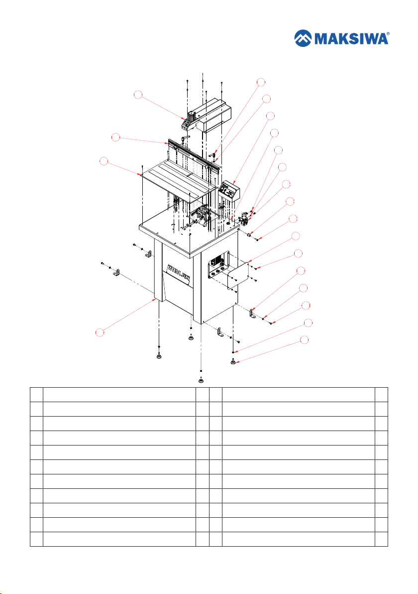
10. PHM.30 HOLE MACHINE EXPLODED VIEW
4
3
2
19
20
5
6
9
10
8
11
12
7
13
14
15
16
1
No
Description
1
HOLE MACHINE BODY
2
WOOD TABLE WITH SANDER
3
DEPTH SCALE WITH KNOBS
4
PROTECTION AND CYLINDER SET
5
PANEL CONTROL
6
TABLE SET
7
ELECTRIC BOX COVER
8
PRESSURE REGULATOR SET
9
TAP BOLT M6X10 ZINC PLATED STEEL PITCH 1,0
HEX NUT M6 ZINC
10
Qty
No
Description
1
11
TABLE ARTICULATOR SHAFT
1
12
TAP BOLT M8X25 ZINC PLATED STEEL PITCH 1,25
1
13
PHILLIPS HEAD PAN SCREW M6X12 PICTH 1,0
1
14
BASE BOLT
1
15
HEX NUT M8
1
16
TAP BOLT M8X16 ZINC PLATED STEEL PITCH 1,25
1
17
FOOT LEVEL 4013 M8X30
1
18
HEX NUT M8 ZINC PLATED STEEL PITCH 1,25
6
19
DEPTH SCALE KNOBS
HEX NUT M8 ZINC
10
20
18
17
Qty
2
2
4
4
4
4
4
4
2
12
13
Page 14
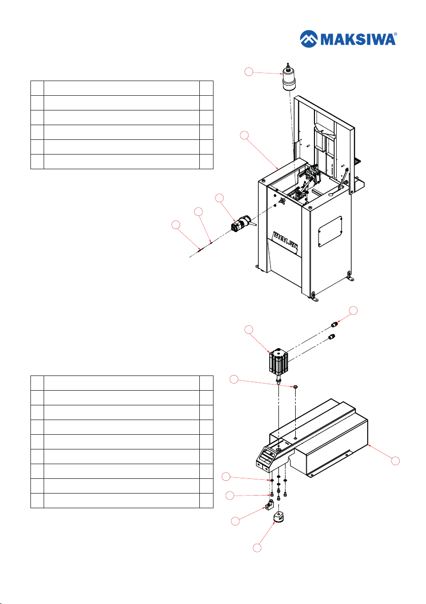
11. ROUTERS EXPLODED VIEW
No
Description
1
ROUTER BOSCH 1,0 HP
2
DRILL ADAPTER
3
DRILL
4
ROUTER BOSCH 2,25 HP
5
PHM.30
4
Qty
1
1
1
1
1
2
3
5
1
6
5
12. PROTECTION AND CYLINDER SET EXPLODED VIEW
No
Description
1
PROTECTION SET
2
TAP BOLT M6X10 ZINC PLATED STEEL PITCH 1,0
3
PISADOR SET
4
LASER SUPPORT
5
ADN-40-40-A-PPS- A
6
STRAIGHT CONNECTION QUICK SCREW 1/4” HOSE 6”
7
THREAD GUIDE
8
HEX NUT M6 ZINC
Qty
1
4
1
1
1
2
1
4
14
7
1
8
2
4
3
Page 15
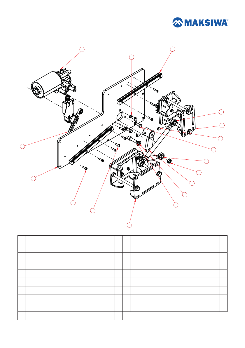
13. SYSTEM CUTTER EXPLODED VIEW
15
13
17
1
3
12
2
7
6
9
14
5
11
4
10
8
No
Description
1
CUTTING SYSTEM MAIN SUPPORT
2
RAIL GUIDE
3
TAP BOLT M4X16 ZINC PLATED STEEL PITCH 0,7
4
CUTTING SYSTEM ENGINE CONNECTING ROD
5
CUTTING SYSTEM MINOR STEM
6
ROUTER SUPPORT
7
CUTTING SYSTEM BIGGER STEM
8
TAP BOLT M8X30 ZINC PLATED STEEL PITCH 1,25
9
TAP BOLT M4X16 ZINC PLATED STEEL PITCH 1,25
16
Qty
No
Description
1
10
HEX NUT M8
2
11
HEX NUT M8 ZINC PLATED STEEL PITCH 1,25
7
12
TAP BOLT M5X16 ZINC PLATED STEEL PITCH 0,8
1
13
HEX NUT M6
1
14
TAP BOLT M6X16 ZINC PLATED STEEL PITCH 1,0
1
15
BOSCH MOTOR 24V
1
16
MOTOR SUPPORT
1
17
END COURSE FM8108
2
Qty
1
1
2
3
3
1
1
1
15
Page 16
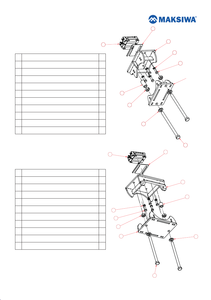
14. ROUTER BOSCH 1,0 HP SUPPORT
EXPLODED VIEW
No
Description
1
PATIM H15
2
CUTTING SYSTEM SPACER
3
HEX NUT M8 ZINC PLATED STEEL PITCH 1,25
4
ROUTER LOCATOR SUPPORT
5
ROUTER SUPPORT LOCK
6
SHIM 2 MM SYSTEM CUTTING PATIN
7
TAP BOLT M5X16 ZINC PLATED STEEL PITCH 0,8
8
TAP BOLT M8X120 ZINC PLATED STEEL PITCH 1,25
9
HEX NUT M5 ZINC
HEX NUT M8 ZINC
10
15. ROUTER BOSCH 2,25 HP SUPPORT
EXPLODED VIEW
Qty
6
1
1
1
2
1
1
1
4
2
6
2
2
3
10
2
4
9
7
8
5
No
Description
1
CUTTING SYSTEM MOTOR SUPPORT
2
PATIM H15
3
CUTTING SYSTEM SPACER
4
HEX NUT M8 ZINC PLATED STEEL PITCH 1,25
5
SHIM 2 MM SYSTEM CUTTING PATIN
6
ROUTER SUPPORT LOCK
7
TAP BOLT M8X120 ZINC PLATED STEEL PITCH 1,25
8
TAP BOLT M5X16 ZINC PLATED STEEL PITCH 0,8
9
HEX NUT M5 ZINC
HEX NUT M8 ZINC
10
16
Qty
1
1
1
2
1
9
1
8
2
4
4
2
4
6
7
1
3
10
Page 17
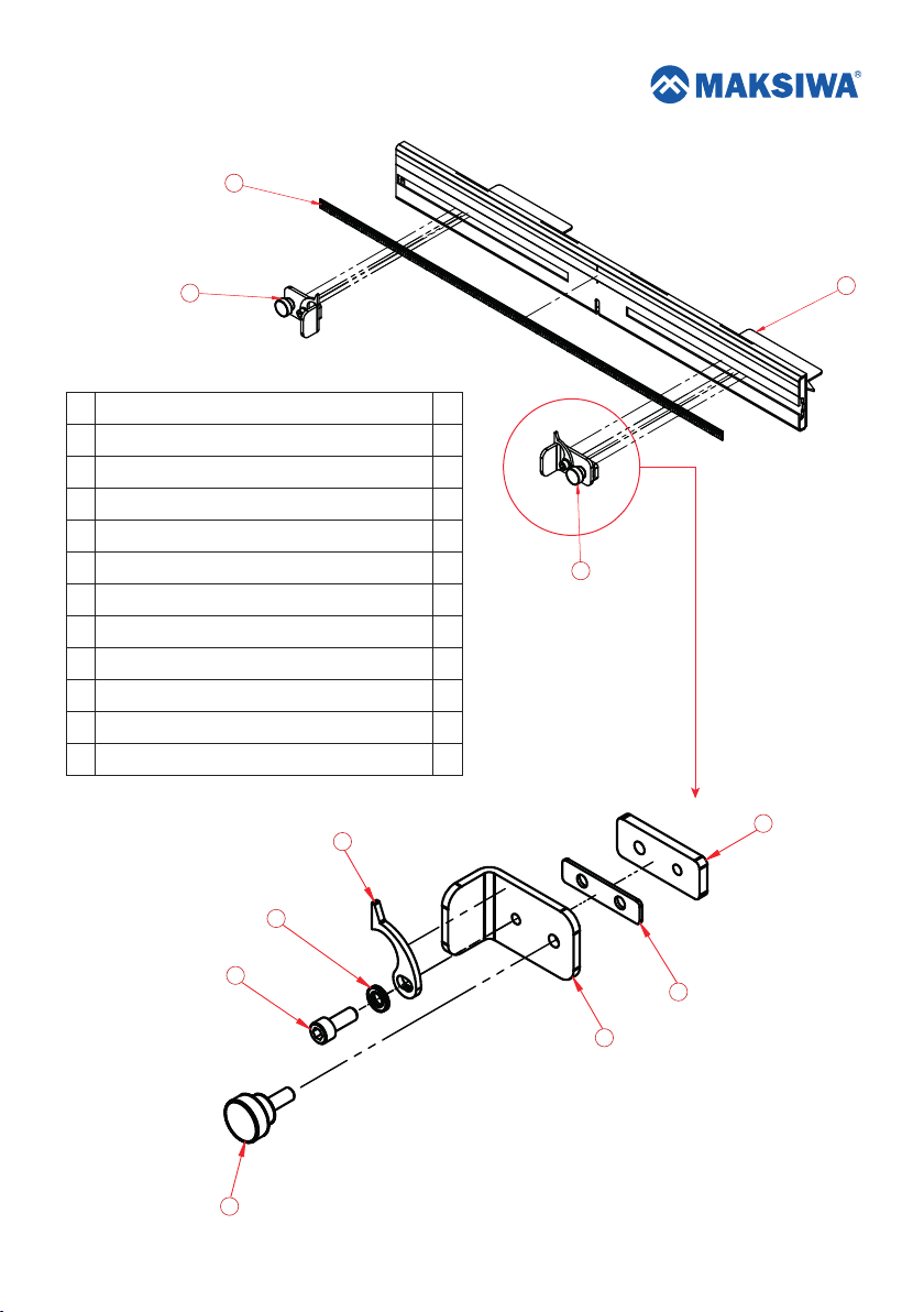
16. DEPH SCALE WITH KNOBS
2
3
No
Description
1
TABLE MOBILE GUIDE
2
MILIMETTERS AND INCHES SCALE
3
LEFT KNOB
4
RIGHT KNOB
5
STOP
6
INDICATOR SPACER
7
NUT / SCALE
8
INDICATING POINTER
9
KNOB M6X16 PLATED STEEL PITCH 1,0
HEX NUT M6 ZINC
10
11 1TAP BOLT M6X16 ZINC PLATED STEEL PITCH 1,0
10
1
Qty
1
1
1
1
1
1
1
1
1
1
8
4
7
11
5
9
6
17
Page 18

 Loading...