


CAUTION!
READ CAREFULLY BEFORE
USING THE DEVICE!
This is a highly sophisticated electronic device. Do not attempt to
assemble and operate the device before reading the Instructions
Manual.
Do not start searching before determining the ground balance. Devices with poor ground balance will not produce accurate results.
Magnetic fields may interfere with this device. If you run in to this type
of interference simply reduce your sensitivity and then continue detecting.
Protect the coil from possible impacts.
Do not expose coil to direct heat sources. Do not apply excessive force
during assembly and use.
Align the battery and carefully place it in its slot in the proper direction.
Do not force the battery in to the holder.
To obtain maximum performance, do not expose battery to excessive
heat. Charge the battery at room temperature.
Do not apply force on the LCD display.
To prolong battery life, discharge it monthly by attaching it to the charging device. Always keep the battery in a charged state when storing
the device.
Metals with an alloy structure (such as lead, galvanized, etc.) which
have remained under ground for a long time may deteriorate and
on occasion produce a gold eect.
Positions of dierent metals under the ground eect the sensing
of the device and cause it to misinterpret those objects as gold or
precious.
1-
2-
3-
4-
5-
6-
7-
8-
9-

CONTENTS
Parts and Accessories
Charging Battery
Assembly
Usage
Usage with Mode 1 (Visual System)
What Is Ground Balance
Mode 1: Adjusting Ground Balance
Mode 1: Search and Cavity Detection
Mode 1: Interpreting Oscilloscope Data
Mode 1: Eliminating Ferrous Metals
Mode 1: Target Analysis
Mode 1: Determination of Target Depth
Mode 1: Recording and Examining The Records
Usage With Mode 2 (Audio System)
Mode 2: Ground Balance
Mode 2: Search and Metal Detection
Technical Specifications
1
5
5
7
9
11
12
14
16
18
18
19
21
22
24
25
26
Thank You for Choosing Makro Detector.
PARTS and ACCESSORIES
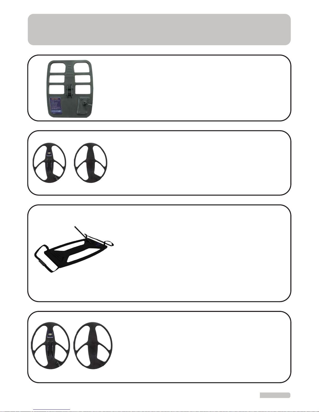
Mode 1 - T100 Coil & Coil Cover (Optional)
60 x 100 cm (23.6 x39.3 inches)
This is a coil developed for deep searches and handled by
two persons. A separate control box and a carry bag are
available for this coil. This system operates only in Mode
1. When sensitivity is adjusted to 6 and lower levels, it will
be possible to make comfortable searches without any
interference from mineral structures and small metals
without any need for ground adjustment.
This coil is more eective in detecting single coins and smaller objects. All results of this system are monitored through
an audio alert. This coil can only be used in Mode 2.
Mode 2 - C32 Coil & Coil Cover
26 x 32 cm (10.2 x 16.2 inches)
This is the largest and deepest coil designed for use in
Mode 2. All results of mode 2 are monitored through an
audio alert only. This coil can only be used in Mode 2.
Mode 2 - C47 Coil (Optional)
39 x 47 cm (15.3 x 18.5 inches)
Mode 1 - T44 Coil
36 x 44 cm (14.1 x 17.3 inches)
This is the coil used in searches for General Purpose. User
monitors the results through the LCD display located on
system box. This coil can only be used in Mode 1.
1
2
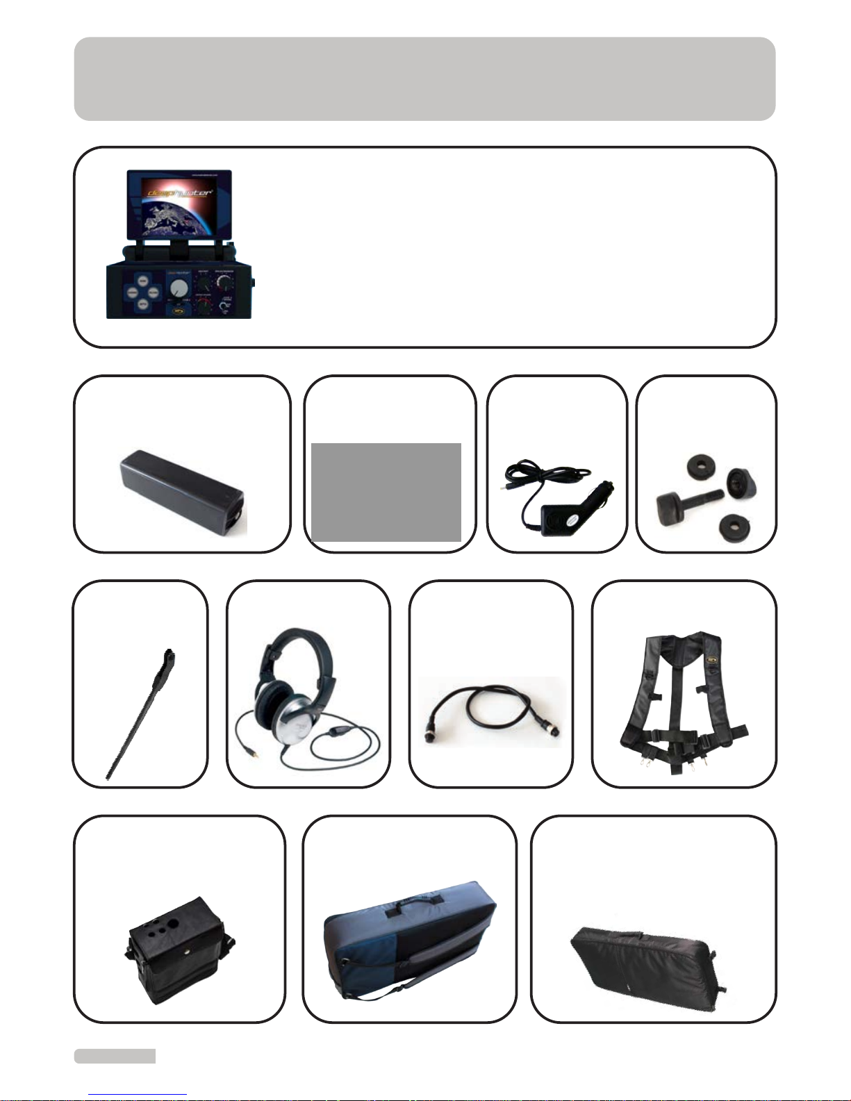
PARTS and ACCESSORIES
This is the main control box. On this device you will find the
coil connection, headphone jack, handset feed inlet and
battery connection. Target results are evaluated and presented to user on the large color LCD Display.
In addition, the control box is equipped with an apparatus for
easy handling.
Electronic System Unit
Headphones
Extension
Shaft
Connection
Cable
Carry Vest
Lithium Polymer
Rechargeable Battery
AC Charger
Vehicle
Charger
Fittings
Deep Coil Carry Bag
(Optional)
System
Carry Bag
Leather Carry Bag
for System Box
3
PARTS and ACCESSORIES
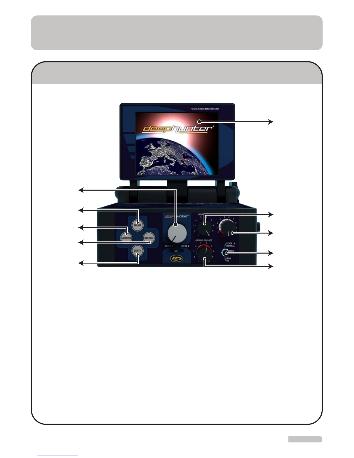
SYSTEM (CONTROL) UNIT
ON/OFF BUTTON: This Control is used for
turning the device On and O. It will also
determine which mode the device will operate in.
MENU: This is the Control for switching to the
Settings Menu in Mode 1.
GROUND: This is the Control for switching to
Ground Balance Menu in Mode 1.
RECORD: This is the Control for entering the
record screen. This is accessed from the menu
and used for recording the target Analysis
report in Mode 1.
DEPTH: This is the Control to switch to the
Depth section in Mode 1. This is used for depth
analysis.
1-
2-
3-
4-
5-
6-
7-
8-
9-
10-
SENSITIVITY: This is the Control used for
adjusting the sensitivity in Mode 2.
GROUND SETTING: This is the adjustment
for entering the ground balance in Mode 2.
FERROUS and MINERAL SETTING: This is
the Control for elimination of ferrous metals
and enabling search for highly mineralized
grounds in Mode 2.
FERROUS DISCRIMINATION: This is the
Control for discriminating ferrous metals
with dierent sound alerts in Mode 2.
SCREEN: This is the visual display where
data is presented to the user in Mode 1.
5
4
3
2
1
9
8
7
6
10
4
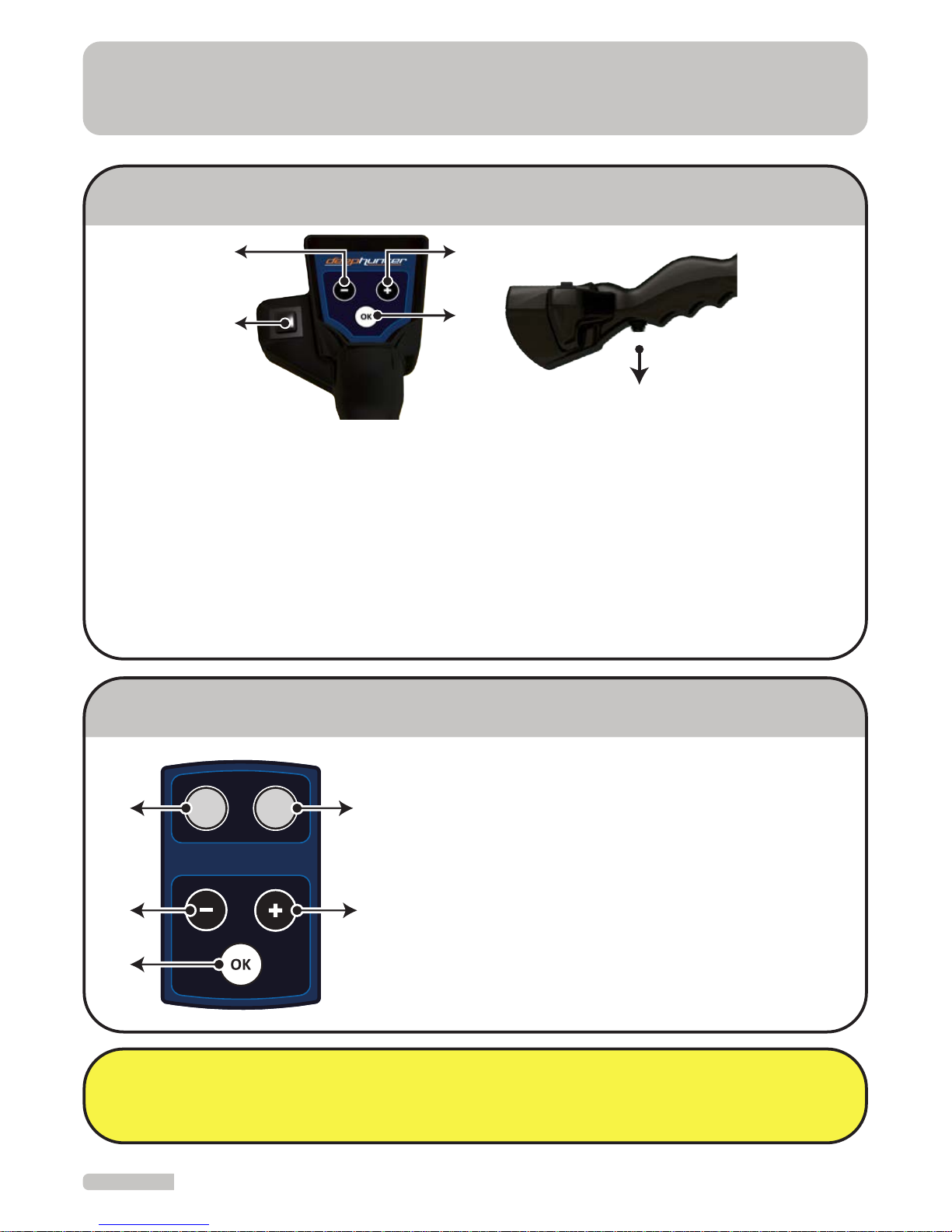
HANDSET
CONTROL BOX for DEEP SEARCH COIL
SCAN: This is the control for enabling the analysis of the target. This should be pressed
while sweeping the coil over the target to be scanned.
OK: This is the control for confirming the current function and switching to the upper
menu.
“–“ : Dash Button.
“+” : Plus Button.
RESET: This is the Control that enables the device to return to the most stable (accurate)
operating settings.
Note: Reset key is a significant key, frequently needed to be used during searches. This
key enables clearing of erroneous signals and data and helps obtaining correct ones.
Frequent use of Reset key would eliminate erroneous incoming signals.
1-
2-
3-
4-
5-
RESET: This is the Control that enables the device to
return to the most stable (accurate) operating
settings.
SCAN: This is the Control for enabling the analysis
of the target. This should be pressed while
sweeping the coil over the target to be scanned.
“–“ : Dash Button.
“+” : Plus Button.
OK: This is the Control for confirming the current
function and switching to the upper menu.
1-
2-
3-
4-
5-
PARTS and ACCESSORIES
2
1
4
3
5
3
5
1
4
2
SCAN
RESET
5
CHARGING BATTERY
ASSEMBLY
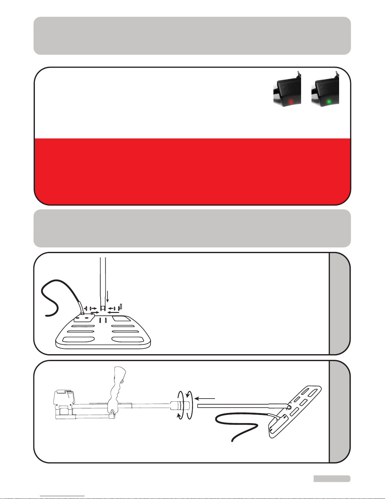
Remove the battery from system box and connect it to the
battery charging device. The light on charger will be red
during charging and turn to green when charging is completed. The light will be green if no battery is inserted in to the
charger or if the battery is fully charged.
WARNING: When storng the devce, remove the batteres from the detector and the charger. For the best results,
batteres should always be kept n a n a fully charged state. Batteres should not be stored n excessvely cold places
such as refrgerators or freezers. The battery should be stored n a dry place and at room temperature. Batteres should
be charged on a fre resstant surface. The devce should only be charged wth the approved charger. Overchargng or
chargng at the wrong voltage wll subject the battery to the rsk of fre. The rsk of chargng at over currents and at
extremely hgh temperatures should not be overlooked.
The chargng tme for a completely empty battery s approxmately 7 hours.
Charging Charging completed
2
123
Loosen the sleeve underneath the handset.
Connect telescopic tube to the lower part of handset.
Tighten and fix the sleeve.
123-
1
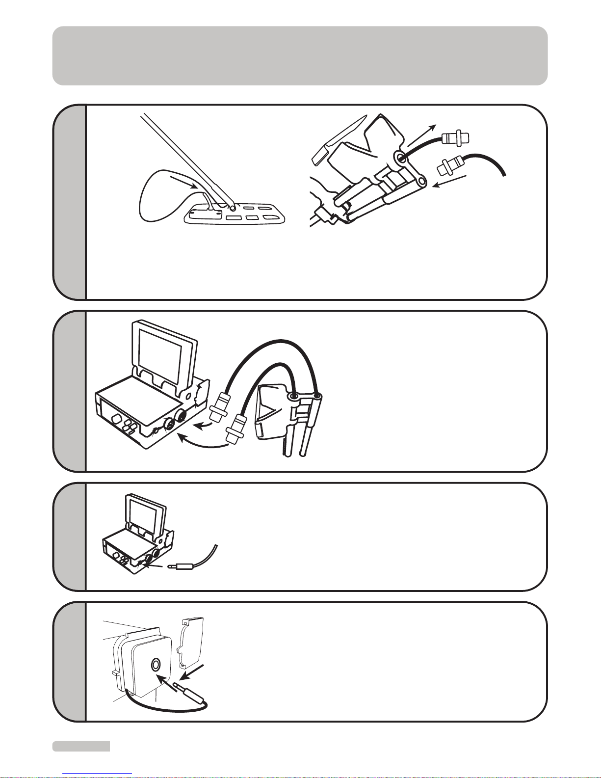
Insert seals into the slots at the end of
extension tube.
Connect extension tube to the connection
point on the coil.
Insert the screw through the hole on the coil
and tighten at the opposite end with a nut.
1-
2-
3-
1
2
3
6
ASSEMBLY
Connect the 9-pin terminal of the
coil to the COIL connector and the
8-pin terminal of handset to HANDSET connection on the system box
and tighten it.
Connect the deep coil control box
to the HANDSET connection on the
deep coil.
1
2
4
1-
2-
If you wish to use headphones, connect the headphone cable to the headphone connection on the
system box.
5
After inserting the battery, connect battery
connection cable to the socket on the battery.
Close the cover by turning it in the direction of
the arrow.
1-
2-
1
2
6
3
Pass the coil cable through telescopic tube.
Pull the cable out from the other end of the tube.
Connect the handset connection cable with 8 pins to the connection point at
the rear of the armrest.
123-
1
2
3

7
USAGE
Ensure that coil always remains parallel to the ground during searches.
RIGHT
Failing to keep the coil in a position parallel to
the ground may cause faulty results.
WRONG
WRONG RIGHT

8
USAGE
CORRECT HOLD
WRONG HOLD

USAGE with MODE 1 (VISUAL SYSTEM)
In case of any existing failures in the coil or the system, “COIL FAILURE” and "SYSTEM
FAILURE" lights will ash at the bottom of the display and warn the operator. If the
warning continues, the user should contact the authorized service center.
COIL FAILURE SYSTEM FAILURE
The device has two separate systems. These systems are called
Mode 1 and Mode 2. Turn On/O button to “Mode 1” position
to operate the device with the screen system. Mode 1 is the
operating mode in which the data obtained is presented to
user with views and sounds. This mode is used for detection of
larger targets at significant depth.
Mode 1 function of the device can be used only with either the 36x44 cm coil or the
60x100 cm coil attached.
Manual reset is available in this part, so there’s no need to sweep the coil continuously. You can continue
to receive signals from the target by holding the coil still over it.
User can make language selection by using “+” and “-”
keys and pressing “OK” button after turning on the
device.
The Device automatically identifies the coil which is
attached to it at the time when it is turned On. The coil
attached will be shown on the screen. If a coil other than
the appropriate one(s) is attached to the device, this will
be indicated on the screen as “COIL FAILURE” warning. In
addition, data regarding the battery status is also shown
on the same screen.
9
USAGE with MODE 1 (VISUAL SYSTEM)
10
Reset Button
CAUTION
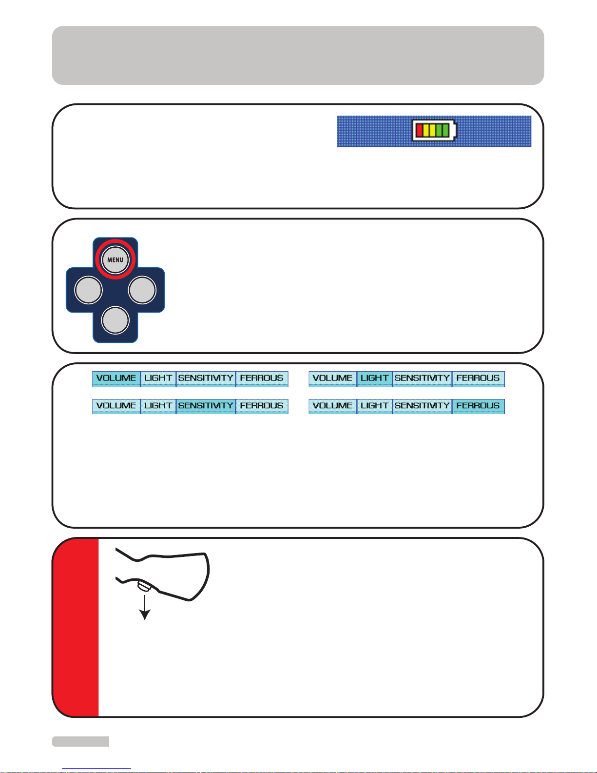
Use of RESET Button: Some interferences arising from
imbalanced motion of the coil and from the environment
may occur while using the device. Such interference is
shown on the device display and can cause the device to
produce an audio signal. Reset the device by pressing the
“RESET” button located under the handset. The Impact of
this interference is eliminated through resetting the device
in this fashion. You should not reset the device while coil is over the target! This
will cause loss of depth, the wrong interpretation of the incoming signal and will
prevent the device from detecting the target. Resetting is done only after the coil
is moved away from the target.
Checking Battery Charge Status
The device will proceed to the “Ground Balance”
section after identifying the attached coil. At the bottom of this section, there is a part
indicating the battery status. The battery should be recharged as required.
By pressing “+” and “-” keys, you will come to the desired area in the “SOUND”, “LIGHT”,
“SENSITIVITY” or “FERROUS” sections, as shown above. After reaching the desired selection, press the “OK” button. The indicator bar will turn from yellow to green. Perform the
desired adjustments by using the “+” and “-” keys and then press the “OK” button. The
Green indicator will again turn to yellow. Now, your adjustments are saved. Repeat the
same steps above to adjust other settings as desired.
Entering Settings Menu
Press the “MENU” button, no matter what section you are in, for
adjusting device features such as sound, light, sensitivity and
non-precious elimination. Current settings will be displayed under
the respective section on the screen. Return to the previous menu
by pressing “MENU” button after you make the adjustment of the
desired selection.
GROUND
DEPTH
RECORD

Land conditions and soil structures may vary between regions (such as sandy soil,
highly mineralized red soil, rocks etc.). In some places, the soil structure even within
the same region may often dier.
Such variances in soil structures mislead the detector and cause the device to sense
this change as a metal object or cavity. For this reason, you should first introduce the
soil structure data of the region to be searched to the device. This definition will block
all potential misleading eects from the ground within that region; which would
otherwise be sensed as misleading signals from the soil. These will be eliminated
through proper setting of the ground control.
A proper ground balance is one of the most important prerequisites for a productive
search. Therefore, it is important that the user pay close attention to variances within
the soil. If you notice misleading signals are being detected by the device from changes in the soil structure, you will need to adjust the ground balance again.
Ground balance is done to enable the device to “sample” the soil structure so that it
can balance out the mineral eect. By adjusting this setting in this fashion, the device
will not be aected by dierent soil structures being reected as metal or cavities. If
the ground balance is not done properly, this will cause loss of depth and false signals
from minerals being interpreted as metals or cavities. Therefore, the ground balance
must be performed as accurately as possible.
With highly mineralized land conditions in mind, the device uses a special ground
balance system to ensure that it can work eiciently in such challenging conditions.
WHAT IS GROUND BALANCE
11

MODE 1: ADJUSTING GROUND BALANCE
After the device is turned On, the “GROUND BALANCE” section will
appear automatically. You should first check your SENSITIVITY
adjustment to be able to obtain accurate results. The Sensitivity
level recommended for new users is 8. When you reach soil structures with varying ground eects during your search and when you
need to renew your ground balance, switch to the Ground section
by pressing the “GROUND” button. You should periodically check
and readjust your ground balance as necessary.
Turn the On/O button to the Mode 1 position. When the
device is On, the Ground Balance screen will appear
automatically.
For adjusting Ground Balance;
1
First, raise the coil approximately 40 cm above the ground
(around your knee level) at the original position and press
the RESET button.
Note: If you fail to raise the coil 40 cm above and begin by
pressing the RESET, no operation to be performed afterwards will be accurate.
4
40 cm
When you enter the Ground Balance menu the current
setting stage is displayed on the screen as “Ground Balance”.
This value will be between -201 and +201.
2
If you run in to a location where you are not able to adjust the Ground Balance this
is caused by one of two situations. 1. You have located a target OR 2. There exists
a mineral structure in the ground that is not suitable for your sensitivity level. In
this case, you should change your position elsewhere from the point which does
not allow such adjustment and retry readjusting the Ground Balance; if still
unsuccessful, the sensitivity level should be reduced by 1 increment.
3
GROUND
DEPTH
RECORD
12

13
MODE 1: ADJUSTING GROUND BALANCE
Raise the coil 40 cm above the ground. Now, keeping the coil parallel to the
ground, press the reset button and lower the coil to 3 cm.
5
40 cm
3 cm
Reset
If the device receives “-” eects, raise the coil 40 cm and press “-” key; if the eect is
“+”, press “+” key for a while and then press the RESET button and lower the coil to
the ground holding it at a distance of 3 cm above the ground. Repeat this process
until the eect is completely removed (until the signal on device disappears).
8
40 cm
3 cm
Reset
If there is ground eect on device, this eect will
be seen on the “GROUND EFFECT” bars as shown
in the figure. In this case, the device is ready for
search. Simply press the OK button to switch to
the Search section.
6
If there is ground impacting the device, this
eect will be shown as “GROUND EFFECT” on the
bars as shown in the figure. To remove this eect,
press “-” key for "-" eects and “+” key for "+"
eects. Repeat the steps 8-10 until this eect is
removed.
7

14
MODE 1: SEARCH AND CAVITY DETECTION
After the eect is completely removed, press the OK button as the coil is lowered
down to 10 cm. Now switch to the search mode and start searching.
10
3 cm
10 cm
Hold the coil at a distance of 10 cm from the ground. Be sure that the coil is parallel to the ground. Sweep the coil with slow motions from left to right for accurate
target detection.
Be sure that you keep your search coil within 3-40 cm at all times. This will maintain the proper Ground Balance. If you exceed these limits, you will receive false
signals.
1
10 cm
10 cm
The device will produce an audio signal when it
detects metal or a cavity. A signal will be produced from the following items: CAVITIES, METAL,
FERROUS or PRECIOUS bars. The eect of the
target can be monitored consecutively on the
graph (Oscilloscope) located above these bars.
In this graph, an ascending graph would be
obtained for metal targets and a descending
one for targets like cavities or voids.
2
In the case that the ground eect cannot be removed, reduce Sensitivity Level by
1 increment and repeat the above process.
9
MODE 1: ADJUSTING GROUND BALANCE

15
MODE 1: SEARCH AND CAVITY DETECTION
If the target is a cavity, an inclination on the
“CAVITY” bar and a descending graph on the
graphic display will be shown. The strength of
the “CAVITY” bar would be shown numerically
at the top, depending on the target’s depth of
eect.
3
If the target is a precious metal, an inclination is
expressed numerically, depending on the depth
of eect. This will be shown on both the "METAL"
and the "PRECIOUS" bars. Metal eect can also
be monitored in the graph located above the
bars.
4
If the target is a ferrous metal, an inclination expressed numerically, depending on the depth of
eect, would be observed both on the "METAL"
and the "FERROUS" bars.
5
When you receive a warning from the device at any point, take the device away
from that point and reset it. Next sweep the coil over the same point again. This is
done to confirm the presence of a target.
6

16
If the target is one small piece of
metal and close to surface,
1
The Oscilloscope is the portion of the screen
where signals received by the device. These
signals are displayed at the top of the search
screen. Viewing this data provides you with a
real time interpretation of the signals from
the ground and the targets below.
If the target is two small pieces of
metal and close to surface,
2
If the target is two small pieces of
metal and at a slightly deep level,
3
If the target is one large piece of
metal and close to the surface,
4
If the target is one large piece of
metal and at a slightly deep level,
5
If the target is one large piece of
metal and at a very deep level,
6
INTERPRETING OSCILLOSCOPE DATA

17
If the target is a cavity quite close
to surface,
7
If the target is a cavity quite deep
from surface,
8
If the target is a cavity and very
deep from surface,
9
If the target is a piece of metal
within a cavity,
10
11
If the Oscilloscope continuously shows a straight line; we can understand from
the incoming signal that the ground structure is very highly mineralized.
Therefore, the device would require a readjustment of the Ground Balance for
the ground in that specific area.
If the signal lines rise vertically and descend likewise, there is no need to obtain the
depth for this target. The reason is that the target is very close to the surface. The
depth measurement obtained would not be accurate.
When real targets are located, the signal on the oscilloscope would not continue
linearly, they will always create a curve on the oscilloscope.
The closer the target is to the surface, the further the oscilloscope will show it from
the central line and vice versa.
INTERPRETING OSCILLOSCOPE DATA

18
MODE 1: ELIMINATING FERROUS METALS
TARGET ANALYSIS
To obtain the analysis of a target detected during
search:
Remove the coil from the target after it is detected
and then press the RESET button.
Press and hold the SCAN key while slowly sweeping
the coil over the target again. Meanwhile, the device
will analyze the target. After leaving the area above
the target, release the SCAN key.
Then, the device will present an ANALYSIS REPORT
to the user. In this report, the type of metal and the
eect of the target reected on the surface are
obtained.
Press “RECORD” key if you wish to save this report, a
message indicating the saving is completed will
appear on the screen.
To exit this screen, press OK or the RESET button.
If the user desires, the device can be adjusted to
eliminate ferrous metals and not report them to the
user. To use this feature the FERROUS setting must be
disabled.
To disable this section, press the MENU button in the
Search and Ground sections. Press “+” key to enter the
FERROUS section and then press the OK button. The
screen will turn from yellow into green and you will
see OFF. Now press the OK button again. Next press
the MENU button again to return to the previous section.
The device will eliminate ferrous metals after this operation. To enable detection of
ferrous metals again, repeat above steps to bring the frame to ON position.

19
DETERMINATION OF TARGET DEPTH
To determine the depth of a target detected during search:
After determining the
eect of the target reected to the surface, press the
DEPTH key.
4
DEPTH
Measure the width
and length of the
frame you obtain.
3
Target
Width
Length
User should first determine the dimensions of
the target as reected to the surface. For this,
bring the coil towards the target by using the
coil’s side; the front and rear parts of the coil
are not used during this measurement.
1
Target
2
To determine the diameter of the target, mark
the first points at which you receive a signal in
four directions.
Target
5
To enter the determined width value, bring the yellow frame to “Width” by using
“+” and “-” keys. Press OK button to ensure the frame is turned into green. Enter
the determined value by using “+” and “-” keys and press “OK” button.
and

20
DETERMINATION OF TARGET DEPTH
6
Maximum value that can be entered for width and length is 160 cm. If measured
values exceed 160 cm, enter 160 cm into the respective field and perform a depth
scan.
7
After entering these values, press and hold the
SCAN button and sweep the coil over the target,
release the SCAN button after the signal disappears.
8
At the end of these processes, a Depth Report
showing the depth and measurement values
entered will be obtained. The value obtained
is an approximate one.
Press the “RECORD” key if you wish to save this
report, a message indicating the saving is
completed will appear on the screen.
Press the OK button or the “Reset” trigger to
exit this report.
The device will return back to the Depth
mode; you can switch to the Search mode by
pressing the DEPTH button.

21
To save the Reports obtaned:
To retreve a saved record for revew at a later tme:
To delete records:
After obtaining the
Analysis and Depth
Reports, press the
RECORD button to save
the Analysis Report.
Press OK button after a the completed
message appears on the screen to
indicate that the information has been
saved.
A maximum of 20 records can be saved
on the device.
Enter the Recording menu by pressing
the RECORD key in the search mode.
Records can be reviewed by
using the “+” and the “-” keys.
Press the OK button while viewing the
record that which you wish to delete.
Use the “+” and the “-” keys to
select Delete the Record and
Exit the window on the left
side of the screen.
1
After pressing the OK button, scroll
to EXIT for exiting the recording
menu or scroll to DELETE RECORD to
delete the record by using the “+”
and the “-” keys.
2
RECORDING AND EXAMINING THE RECORDS
RECORD
RECORD

22
USAGE with MODE 2 (AUDIO SYSTEM)
Turn the On/O button to the Mode 2 position. When the device
is turned on, the opening sound will play. After approximately 10
seconds, the device will be ready to use with the active audio
alert.
In Mode 2, target detection is performed with audio alerts only. This mode is recommended to be used for the detection of small objects and metals such as single coins.
This mode can be used only when Mode 2 compatible search coils are attached.
Snce Mode 2 s a system runnng on the moton prncpal, the col should be n contnuous moton. Move the col from left to rght over the ground for metal detecton.
IRON DISCRIMINATION
IRON DISCRIMINATION
Auto.
OFF
This is the key that enables the discrimination of ferrous metals
from precious ones based on dierent audio alerts. With the use
of this key, the user is able to conduct searches in highly mineralized soils containing iron minerals (humid and plowed soils, soils
containing high amounts of iron and places such as beaches etc.).
As this key is turned from 1 towards 10, a loss of depth will be
seen for some metals. As this key is turned towards 10, the ferrous
discrimination of the device increases. The interval at which metals are detected the
deepest is between 1 and 3. Metals are detected with a single audio tone. Above 4,
metals are discriminated with audio tones; for ferrous metals a low tone and for precious
metals and gold, two dierent but similar high tones will be produced.
Automatic (Auto): This is the setting where metals are discriminated as ferrous and
precious. This setting is recommended for use where ground structures require. You can
use this setting where metal discrimination is required but ferrous discrimination is not.
GROUND BALANCE
This is the adjustment made to eliminate the interferences
originating from the minerals within the ground. Ground Balance enables device to operate with a higher performance in
dierent ground structures and prevents it from giving false
signals due to the minerals within the soil.
GROUND SETTING

23
USAGE with MODE 2 (AUDIO SYSTEM)
Iron On: If you wish to see ferrous metals during your search, use
this mode. To enable ferrous metals to be detected with dierent
sound tones, the ferrous discrimination key should be set to
automatic or positioned between 5 and 10.
Iron O: Conduct your search in this mode to prevent your
device from producing signals for ferrous metals. The Ferrous
discrimination key should be set tautomatic or positioned
between 5 and 10 for searches conducted in this mode.
Beach & Mineral: Conduct your searches in highly mineralized
soils or at beaches where you face diiculty in setting the ground
balance. To conduct the search in this mode, the Ferrous Discrimination must be at position 10. In this position, the device will
not be aected by the iron content or high levels of minerals
contained within the ground. It will not produce signals for
ferrous metals, however a reduction in metal detection depth
will occur. If you continue to receive signals from highly mineralized ground, simply reduce the sensitivity level.
IRON and MINERAL SETTINGS
IRON
ON
BEACH &
MINERAL
IRON
OFF
This adjustment is used to reduce the interference the device
receives from the surrounding environment due to electromagnetic waves and the eects from the ground. Moreover, this is the
depth adjustment of the device. When the device is set to the
maximum sensitivity, the depth is also maximized. However, as
the sensitivity is increased, the sensitivity of device towards electromagnetic waves and ground eects will also increase. The user
will have to reduce the sensitivity level to a point where the device
is stable and produces a comfortable operation with minimal
interferences from the environment.
SENSITIVITY ADJUSTMENT
SENSITIVITY

24
MODE 2: GROUND BALANCE
Bring the Ground Balance to position 1. Sweep the coil from left to right at 5 cm above
the ground. If the device receives any interference, to remove it, increase the Ground
Balance level in small increments while sweeping the coil at the same time. Leave the
setting at the point where the sound goes o. Now, your Ground Balance is complete.
If the Ground Balance is still not matching at position 10, reduce the sensitivity level
incrementally and repeat the above steps. If you still receive intense eects from the
ground even when the sensitivity is reduced, then the soil may be rich in the mineral
iron. In this case, try adjusting the Ground Balance again after bringing the Ferrous and
Mineral Adjustment to Beach & Mineral and the Ferrous Adjustment to 10.
If your search area has a highly variable structure, adjusting Ground Balance at points
where you receive the highest eects from the ground (such as over rocks or pits)
would minimize the ground eect during your search.
NOTE: You may need to readjust the Sensitivity and Ground Balance when the eects
from ground or environment vary.
After Ground Balance passes to the red marked area, depth
loss may occur for precious metals other than gold. When
the Ground Balance is at position 10, the device will not
sense ferrous and precious metals except gold. Therefore, if
you are also searching for precious metals, you should keep
the Ground Balance between the blue and orange areas. If
the Ground Balance does not match within these areas,
enable it to match by reducing the sensitivity level. The
recommended Ground Balance level is 4-6.
CAUTION
5 cm
GROUND BALANCE
GROUND BALANCE
GROUND BALANCE

25
MODE 2: SEARCH and METAL DETECTION
Hold the coil at a distance of
5 cm from the ground. Be
sure that the coil is parallel
to the ground. Sweep the
coil with slow motions from
left to right for accurate
target detection.
5 cm
Mode 2 is a system that operates under the motion principle. Therefore, the coil
should be kept in constant motion to enable the device to detect metals. Since the
device runs on an automatic reset principle, if you keep the coil still over the target, it
will not detect the metal.
Target Target
You can detect metals which are hard to detect
more easily if you sweep the coil from left to
right in both directions over the area to be
scanned.
The Device will produce a sound alert when it detects metal. To check the target,
sweep the coil over the same target several times to confirm that you receive the
same signal.

26
Battery
Operating Voltage
Battery Charger
16.8 V 3300 mA Lithium Polymer, rechargeable
12 V - 16.8 V
AC 100 - 240V / 50 - 60 Hz - DC 16.8 V / 500mA
320 gr
Battery Weight
Dimensions
Weight
21x18x8,5 cm
8,2” x 7“ x 3,3”
1.380 gr
3 Pounds
36x44 cm
14” x 17,5”
1.400 gr
3 Pounds
60x100 cm
23,5” x 40”
6.450 gr
14.2 Pounds
26x32 cm
10” x 12,5”
850 gr
1.85 Pounds
39x47 cm
15” x 18,5”
1.200 gr
2.65 Pounds
85-135 cm
33” - 53”
1.000 gr
2.2 Pounds
T44 CoilControl Unit
T100 Coil
(Optional)
C47 Coil
(Optional)
StemC32 Coil
TECHNICAL SPECIFICATIONS
Operating System
Frequency
Metal Detection
Sensitivity Adjustment
Ground Balance
Headphone Output
VLF
12.5 KHz
Display and Sound
1/4'' Stereo
Manual
Manual
VLF
17.5 KHz
Sound
MODE 1 (VISUAL SYSTEM) MODE 2 (AUDIO SYSTEM)
Warranty Perod s 2 years.
Note: Battery, bags, headphones and battery charger
devices are not included in the warranty coverage.

 Loading...