

Page 1 of 13
PPH MAKOT
ul. Przewóz 34/304
30-716 Kraków | Poland
www.makot.pl
+48 537 872 522 (Sales Department)
+48 602 260 992 (Technical Department)
biuro@makot.pl (Sales Department)
dt@makot.pl (Technical Department)
1. DESCRIPTION.
The UMS-02 controller is a programmable time controller with universal application.
Its main purpose is to control external devices in the process of washing milk coolers and
milking devices, however it is also used, for example, in cleaning tanks for beer wort,
juice tanks, car washes, or juice production equipment.
The controller’s casing in the UMS-02H version has an IP52 protection class and is
designed for built-in. Controller’s electronics is able to work at temperature up to -10 OC.
The controller can work in an automatic cycle, according to one of four factory (default)
washing programs (with the possibility of their modification) or a program created by
the user. There is also the option of manually activating a vacuum pump or a stirrer.
2. TECHNICAL DATA.
casing dimensions
123 x 68 x 85 mm
power supply
230 V AC 50 Hz
protection class: - UMS-02
- UMS-02H
IP 20
IP 52
safety class
CE
number of relay outputs
6
load capacity of the relay contacts
10 A 250 V AC
number of control inputs
2
(hydrostatic & external program start button)
type of display
LED
number of available programs
8
number of factory (default) programs
4
maximum number of steps in each program
50
minimum duration of one step
1 s.
maximum duration of one step
99 min.
Page 2 of 13
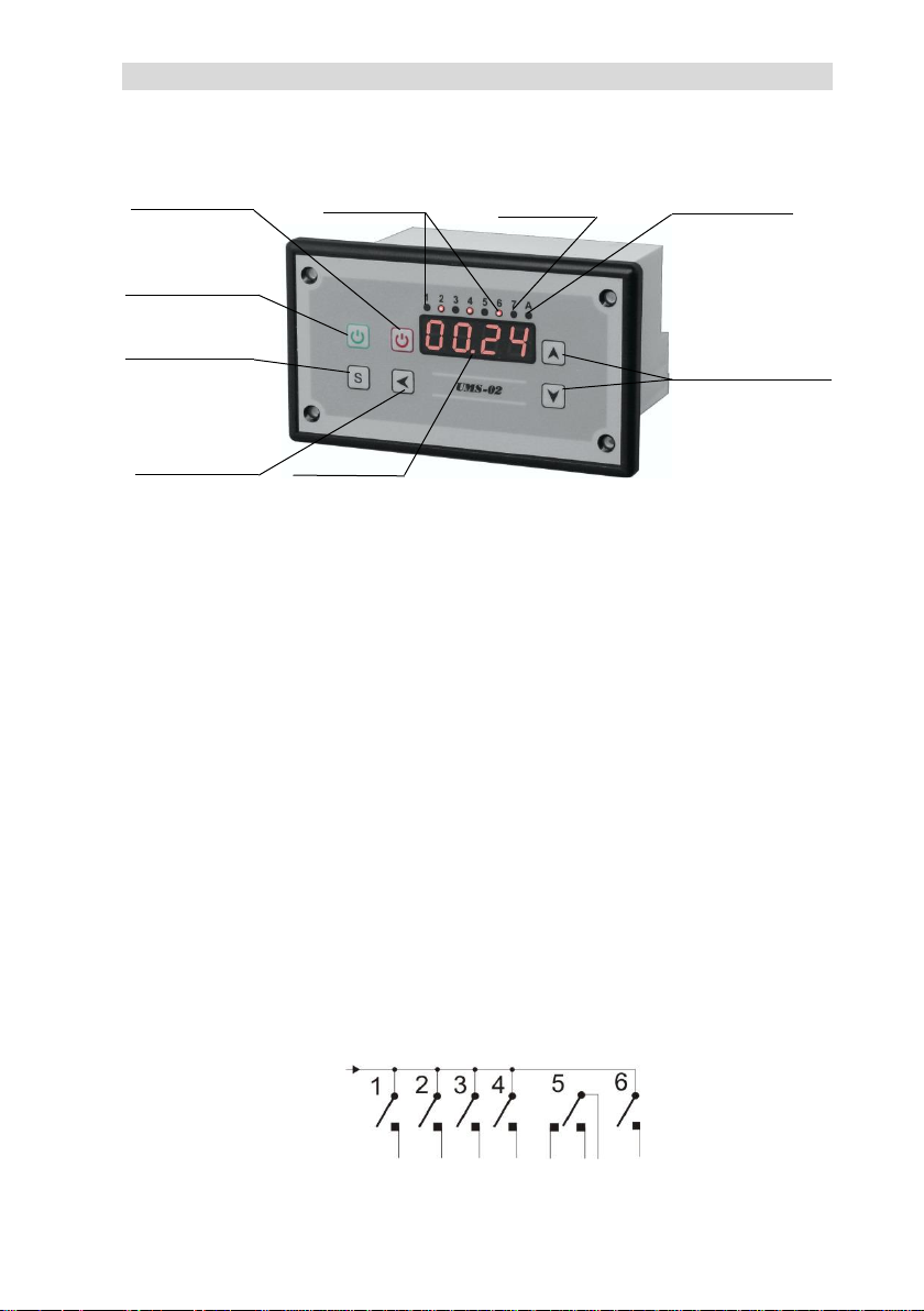
3. CONSTRUCTION.
The UMS-02 controller is placed in a panel casing, intended for built-in, containing all
control and executive elements:
The controller is equipped with:
✓ LED display, indicating the remaining time, during program execution, until its
completion [1],
✓ LED diodes indicating which relay is currently switched on during program execution
[2],
✓ LED diode indicating hydrostatic operation activated [3],
✓ LED diode signaling operation in test mode [4],
✓ button that activates the program; this button is also used to manually pause
the program [5],
✓ button that disables the program [6],
✓ button for manually switching the relay no. 3 or no. 4 on and off and setting button
in the service mode (changing settings of the regulator's operation) [7],
✓ entry button in setting mode [8],
✓ setting buttons (activated in setting mode and during test mode) [9].
The controller also has:
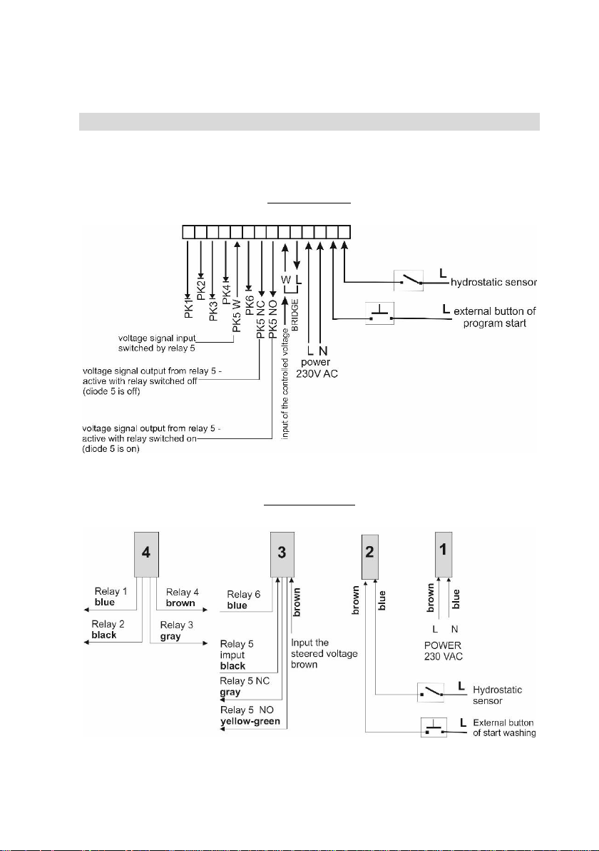
✓ 6 control outputs: in relays 1-4 and 6 the outputs have normal open contacts,
whereas relay no. 5 has normal closed and normal open contacts and a switched
voltage input, which may have a different value than the other relays,
✓ switching voltage input for relays 1-4 and 6, led out to enable connecting any voltage
level from 6 to 380 V,
settings entry button [8]
display [1]
setting buttons
(active in setting mode
and test mode) [9]
manual switch on/off
of relays 3 or 4 button
and setting button in
service mode [7]
program stop button [6]
program start and
pause button [5]
relays operation
signaling [2]
hydrostatic operation
signaling [3]
test mode signaling [6]
Page 3 of 13
✓ input for hydrostatic connection,
✓ input for connecting an external button that activates the program.
4. SCHEME OF CONNECTION OF THE CONTROLLER.
Connecting the controller to the device that is to be controlled is illustrated by the
following drawings:
UMS-02 version
UMS-02H version

Page 4 of 13
ATTENTION
1. On the external start button and the hydrostatic input, the 230 V AC signal L should
be given.
2. Relay no. 5 has normal open (NO) and normal closed (NC) inputs.
5. OPERATING THE CONTROLLER BY A DIRECT USER.
The controller is characterized by the ease of use by a direct user. Operation is limited
to using two or three buttons. The other buttons are inactive for the direct user, thus
preventing accidental interfering with the factory (default) settings or made by the
installer.
5.1. Launching the controller.
After connecting the supply voltage, the controller remains in a state of readiness
to work, which is signaled by four lines illuminated on the display.
ATTENTION
The time indicated by the display does not take into account the time needed to pour
water in the hydrostatic cooperation mode.
5.2. Enabling and pausing the program.
By pressing the program start button [5] (green button), the previously set or
programmed program is executed.

Page 5 of 13
During the execution of the program, user can pause its execution at any time. This is
done by re-pressing the start button (green) [5]. When the program is paused, all active
relays are switched off. It is restarted by pressing the [5] button again. The program will
be continued from the place where it was paused.
5.3. Disabling the program.
If necessary, the program currently executed by the controller can be disabled at any
time. This is done by pressing the stop button [6] (red color). When the [6] button is
pressed, the program execution is interrupted and deactivated. The controller goes into
the ready state.
ATTENTION
If the program is re-enabled, its implementation will start from the beginning.
5.4. Manual activation of the vacuum pump or the stirrer.
If this function is activated, the user can manually switch on and switch off the vacuum
pump or the stirrer operation; the [7] button is used for this purpose. Manual switching
is only possible when the controller does not execute the washing program; during the
program execution, the switch is inactive. The factory settings or made by the installer
determine which output (PP – vacuum pump or PPR - stirrer) can be switched manually.

Page 6 of 13
6. CONTROLLER FUNCTIONS.
The controller is equipped with a number of functions that, together with the possibility
to create own program, allows the user to adapt the controller to the individual needs
(see 7. PROGRAMMING and 9. SETTING TABLE).
1. Washing programs. The controller has 8 programs. Two programs for washing
of milking devices and two programs for washing milk coolers are pre-programmed.
Factory programs can be freely modified and removed. The remaining 4 places
in the controller's memory allow creating control programs according to the user’s
individual needs.
2. Function of modification and creating programs. The controller enables independent
(by the user) creation of a control program. Each program can concist of a maximum
50 steps (sequences), with a duration of 1 s. to 99 min. each. The programming
method is very simple and intuitive and has been described in detail in the
instruction, in iconographic form. Factory programs can also be modified according
to the needs of the user.
3. Function of protection in the event of a power failure. Loss of power supply
interrupts the execution of the activated washing program. When the power supply
returns, the program will start from the same spot where it has been stopped. In the
settings of this function, one can reduce the time to return to the interrupted work
(in the range from 1 h to 9 h).
4. A service function that allows testing the correct operation of the control system.
This function allows to go sequentially to the next steps (sequences) of the program
without waiting for the duration of a given step to expire. The transition is made by
pressing the appropriate button. The controller has protection against accidental

Page 7 of 13
switching in test mode to the next step during actual controller operation – this
function is only available to the installer.
5. Function of returning to the factory (default) settings. If an error occurs while setting
the controller operation, it is always possible to return to the factory settings.
6. Function of manual switching on and off of the vacuum pump or the stirrer.
7. Program start function. The program is started by manually pressing the button
located on the front of the controller or by pressing the external button
(if connected). It is also possible to trigger the start of the program in an automatic
manner, carried out by an external device, connected to the external button input.
8. Function of pausing the execution of the program during its duration. This function
allows to interrupt the program at any time, until it resumes. The resumption occurs
exactly in the same place where the program was interrupted. Pausing is done by
pressing the button located on the front of the controller or by pressing the external
button.
9. Function of disabling the program. The controller is equipped with a button that
disables the execution of the program, without the possibility of resuming it at the
point of stopping. Re-enabling the program will start the program from the
beginning.
10. Function of displaying the time remaining until the end of the program. During
the program execution, the controller's display shows the time to complete the
entire program. The time indicated by the display does not take into account
the time of pouring water when using a hydrostatic.
11. Function of completing the process of pouring water depending on the signal from
the hydrostatic.
7. PROGRAMMING.
The controller is factory-programmed for standard operating conditions, for the purpose
of controlling the washing of the milk coolers (two programs) and the washing of milking
devices (two programs). Nevertheless, in order to ensure correct operation of the
controller under specific conditions, appropriate adjustments of the operating
parameters can be made, including the selection of the appropriate program.
After installing the controller, one can also check the correctness of the operation of the
entire washing system in test mode.
The controller is protected against accidental entry into the service settings mode,
assuming only those available to the installer or service technician. These safeguards
include:
− the necessity to press and hold the settings entry button [8] for about 15 sec.,
− the necessity to enter the access code, which is given in the table of settings.

Page 8 of 13
ATTENTION
Please do not provide access code to the direct users.
The procedure for entering the access code, allowing entry into the settings and
programming mode is shown below graphically:
7.1. Selection of the parameter to be edited.
In the table of settings all available parameters (functions) are given along with their
description and possible values to be set. If you want to change any parameter from the
available settings, enter the setting mode, and then select the parameter that will be
subject to change. The following is a graphical representation of the change in the factory
setting of the washing program. The program no. 1 is preset at the factory.

Page 9 of 13
7.2. Editing the program – parameter EdPr.
The controller comes pre-equipped with 4 washing programs that can be freely edited,
depending on needs.
The remaining 4 places in the controller’s memory are intended for creating a program
by the installer; they are empty (do not contain any steps). Each program can contain up
to 50 steps (sequences), lasting from 1 second to 99 minutes.
Each step is assigned:
a) state of 6 relay outputs – active relay (signaled by red diodes marked with numbers
from 1 to 6) or inactive relay,
b) hydrostatic input status – active (signaled by red diode marked with number 7) or
inactive,
c) the duration of the step.
7.3. Setting the dosing of detergent.
To control the detergent dispenser, please use relay no. 6, which in the factory programs
is set as a washing relay (signaling that the washing process takes place) and it is active
throughout the entire washing process.
In order to set the relay no. 6 as the dosing relay, enter the settings and follow the
program editing procedure (see 7.2. Editing the program – parameter EdPr). In this case,
relay no. 6 must be deactivated in steps, where there is no dosing of the detergent.

Page 10 of 13
7.4. Return to factory (default) settings.
To return to the factory (default) settings, enter the controller settings. Then use the ▲
and ▼ buttons to select the PdOd parameter, confirm the selection by pressing the S
button and change its value from 0 to 1, using the ▲ button. Then confirm the changes
by pressing the S button again. After doing this, disconnect the power supply from the
controller and switch it on again.
ATTENTION
1. A return to the factory settings removes all settings from the controller's memory
while restoring factory settings. So be careful and consciously use this option.
2. The return to the factory settings takes place only after disconnecting and
re-connecting the controller's power supply.
7.5. Test mode.
The test mode function is used for accelerated checking of the correct operation of the
entire washing system, controlled by the UMS-02 controller. Working in the test mode
consists in the possibility of manually going to the next steps of the program, without
waiting for the end of the duration of a given step.
In order to set the test mode, enter the settings, select UEL parameter and change its
value to 1, and then confirm by pressing the S button. Exit from the settings by pressing
the off button (red). The test operation mode of the controller is signaled by flashing
the green diode, marked with the letter A.
After activating a given program, the transition to its next steps is carried out by pressing
the ▲ button. You can also go back to the previous steps by pressing the ▼ button.
In order to exit the test mode, enter the controller settings, select UEL parameter and
change its value to 0, then confirm with the S button, and then exit the settings
by pressing the off button (red).

Page 11 of 13
ATTENTION
After completing the testing, remember to return to the normal operating mode
of the controller. During normal operation, the green diode A does not light up.
8. FACTORY PROGRAMS.
The controller comes pre-equipped with 4 washing programs that can be freely edited,
depending on needs. There are 2 programs for washing of milking devices (program
no. 1 and no. 2) and 2 programs for washing milk coolers (program no. 3 and no. 4).
Below are the tables containing these programs.
The remaining 4 places in the memory of the controller are designed to create
the program(-s) by the user – they are empty (do not contain any steps).
The abbreviations used in the following tables mean:
CW – hot water relay
ZW – cold water relay
PP – vacuum pump relay
PML – milk pump relay
PM – washing pump relay
PPR – stirrer relay
ZZ – dump valve relay
PMY – washing relay
H – hydrostatic
PROGRAM NO. 1
no. of LED diode
1 2 3 4 5 6 7
comments
no. of relay
1 2 3 4 5 6
no. of step
step duration
CW
ZW
PP
PML
ZZ
PMY
H
1
15:00
0 1 0 0 0 1 1
max. time
2
03:00
0 0 1 0 0 1 0
3 00:30
0 0 1 1 0 1 0
4 15:00
1 0 0 0 1 1 1
max. time
5
07:30
0 0 1 0 1 1 0
6 03:30
0 0 1 0 0 1 0
7 00:30
0 0 1 1 0 1 0 8
15:00
0 1 0 0 0 1 1
max. time
9
05:00
0 0 1 0 0 1 0
10
00:30
0 0 1 1 0 1 0
01:05:30
maximum total time
PROGRAM NO. 2
no. of LED diode
1 2 3 4 5 6 7
comments
no. of relay
1 2 3 4 5 6
no. of step
step duration
CW
ZW
PP
PML
ZZ
PMY H 1
15:00
0 1 0 0 0 1 1
2 04:00
0 0 1 0 0 1 0
3 00:30
0 0 1 1 0 1 0 4
15:00
1 0 0 0 1 1 1

Page 12 of 13
5
11:30
0 0 1 0 1 1 0
6 02:30
0 0 1 0 0 1 0
7 00:30
0 0 1 1 0 1 0 8
15:00
0 1 0 0 0 1 1
9 06:00
0 0 1 0 0 1 0
10
00:30
0 0 1 1 0 1 0
01:10:30
maximum total time
PROGRAM NO. 3
no. of LED diode
1 2 3 4 5 6 7
comments
no. of relay
1 2 3 4 5 6
no. of step
step duration
CW
ZW
PM
PPR
ZZ
PMY
H 1 02:00
0 1 0 0 0 1
2 00:30
0 1 1 1 0 1 3
02:00
0 0 1 1 0 1
4 02:30
0 0 0 0 1 1
5 02:30
1 0 0 0 0 1 6
00:30
1 0 1 1 0 1
7 05:00
0 0 1 1 0 1
8 03:00
0 0 0 0 1 1 9
02:00
0 1 0 0 0 1
10
00:30
0 1 1 1 0 1 11
03:30
0 0 1 1 0 1 12
04:00
0 0 0 0 1 1
28:00
maximum total time
PROGRAM NO. 4
no. of LED diode
1 2 3 4 5 6 7
comments
no. of relay
1 2 3 4 5 6
no. of step
step duration
CW
ZW
PM
PPR
ZZ
PMY
H 1 02:30
0 1 0 0 0 1 0 2
01:00
0 1 1 1 0 1 0
3 01:00
0 0 1 1 0 1 0
4 02:30
0 0 0 0 1 1 0 5
02:30
1 0 0 0 0 1 0
6 01:00
1 0 1 1 0 1 0
7 04:30
0 0 1 1 0 1 0 8
03:00
0 0 0 0 1 1 0
9 02:30
0 1 0 0 0 1 0
10
01:00
0 1 1 1 0 1 0 11
02:30
0 0 1 1 0 1 0 12
04:00
0 0 0 0 1 1 0
28:00
maximum total time

Page 13 of 13
9. TABLE OF SETTINGS.
DESCRIPTION OF THE
FUNCTION
SYMBOL
RANGE OF SETTINGS
FACTORY
SETTING
entry in settings
U000
access code
121
editing the programs
EdPr
editing factory programs and
creating own programs – see
7.2. Editing the program EdPr parameter
8 programs
– see
8. Factory
programs
setting the program
number by default
activated by the
controller
dPro
factory (default) programs
(Pro1, Pro2, Pro3 and Pro4)
and free space for programs
created by the user (Pro5,
Pro6, Pro7 and Pro8)
Pro1
setting manual
switching on and off
of the vacuum pump
or the stirrer
UPP
0 – off
1 – vacuum pump
2 – stirrer
0
test mode
UEL
0 – normal mode
1 – test mode
0
setting the maximum
power interruption
time, after which the
program will be
resumed
UAP
0 – no time limit; program
execution will always take
place, after the power supply
is restored
1 – return to the program
execution will take place,
if the power supply is
restored at the time set by
the user (in the range from
1 h to 9 h)
9 (h)
return to factory
settings (when
restarting
the controller)
PdOd
0 – off
1 – return to factory settings
0
 Loading...