


Page 1 of 13
PPH MAKOT
ul. Przewóz 34/304
30-716 Kraków | Poland
www.makot.pl
+ 48 537 872 522 (Sales Department)
+ 48 602 260 992 (Technical Department)
biuro@makot.pl (Sales Department)
dt@makot.pl (Technical Department)
1. DESCRIPTION.
Temperature regulators of SMT series are a microprocessor-based, programmable
temperature controllers, intended for use i.a. in milk coolers and all types of dryers.
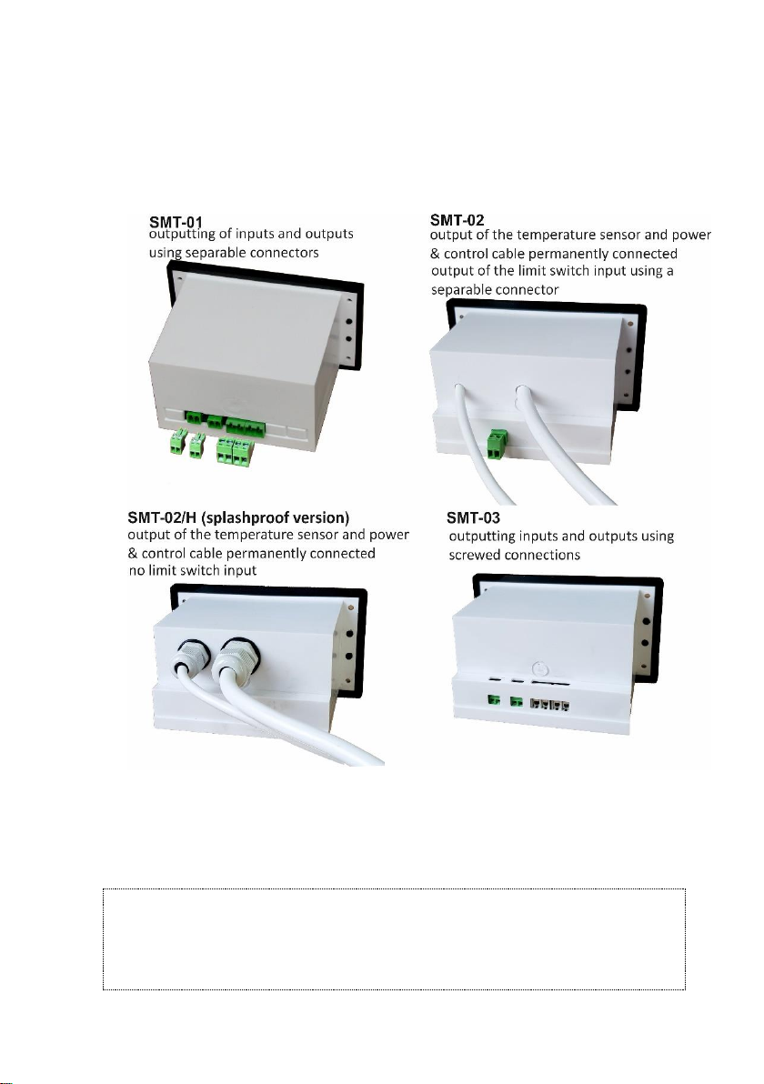
The series includes the following regulators:
− SMT-01,
− SMT-02,
− SMT-02H,
− SMT-03.
Individual types differ from each other in the way of output of control inputs and
outputs. The casing of regulators in this series are adapted for panel mounting.
2. TECHNICAL DATA.
temperature measuring range
between -40 OC and +120 OC
control temperature range
between -40 OC and +120 OC
(decreased by a set hysteresis)
measuring resolution of the
temperature measurer (resolution
of control temperature settings)
1 OC for the range below -9,9 OC
0,2 OC for the range from -10 OC to +100 OC
1 OC for the range over +100 OC
control hysteresis
[programmable parameter]
between 0,2 OC and 10 OC for the range from -10 OC to +100 OC
between 1 OC and 10 OC for the range <-10 OC and >+100 OC
working time of the stirrer
(ventilator)
[programmable parameter]
between 1 min. and 60 min.
standstill time of the stirrer
(ventilator)
[programmable parameter]
between 1 min. and 60 min.
temporary work time of the stirrer
(ventilator)
[programmable parameter]
between 1 min. and 60 min.
time delay for switching the unit /
stirrer on after the regulator is
between 1 s. and 999 s.
Page 2 of 13
turned on or the power supply
decay occurs
length of control sensors
5 m
type of temperature sensor
thermistor NTC
type of temperature measurer
digital LED
load capacity of relay contacts
controlling the unit (heating system)
30 A 250 V AC
load capacity of relay contacts
controlling the stirrer (ventilator)
10 A 250 V AC
power supply
230 V AC 50 HZ
protection class
IP 55
safety class
CE
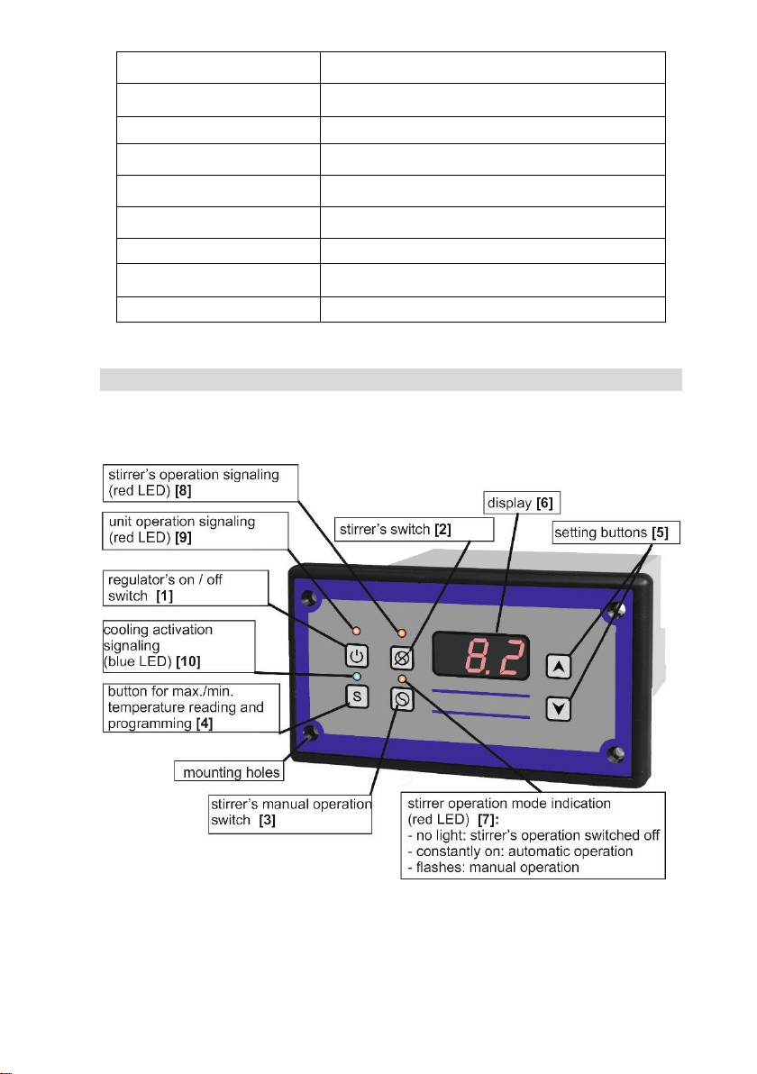
3. CONSTRUCTION.
Regulator SMT is placed in a compact casing, including all control and executive
elements:
The regulator is equipped with:
✓ button for switching the regulator on and off [1],
✓ button disabling automatic stirrer (fan) operation [2],
✓ button enabling manual operation of the stirrer (fan) [3],
✓ digital temperature meter allowing for current temperature control, independently
from switching on or off the regulator [6],
Page 3 of 13
✓ LEDs signaling the current operating status of the cooling (heating) unit and the
stirrer (fan) [7] [8] [9] [10]
✓ input for connecting the limit switch,
✓ control outputs, that is:
− unit control output (heating system),
− stirrer (fan) control output.
In the figure above, the types of outputs and inputs are shown, depending on the type
of regulator.
The regulator SMT-02H v. 3, apart from cable entry through glands, has a sealing
connection of the front part of the casing with its back, which ensures splash-proofness.
ATTENTION
The blue LED indicates the activation of the cooling (heating) mode. If the LED is off,
and the regulator is connected to the mains, it means the cooling (heating) operation
of the regulator is switched off. However, you can switch on the stirrer’s manual
operation by pressing the button [3].
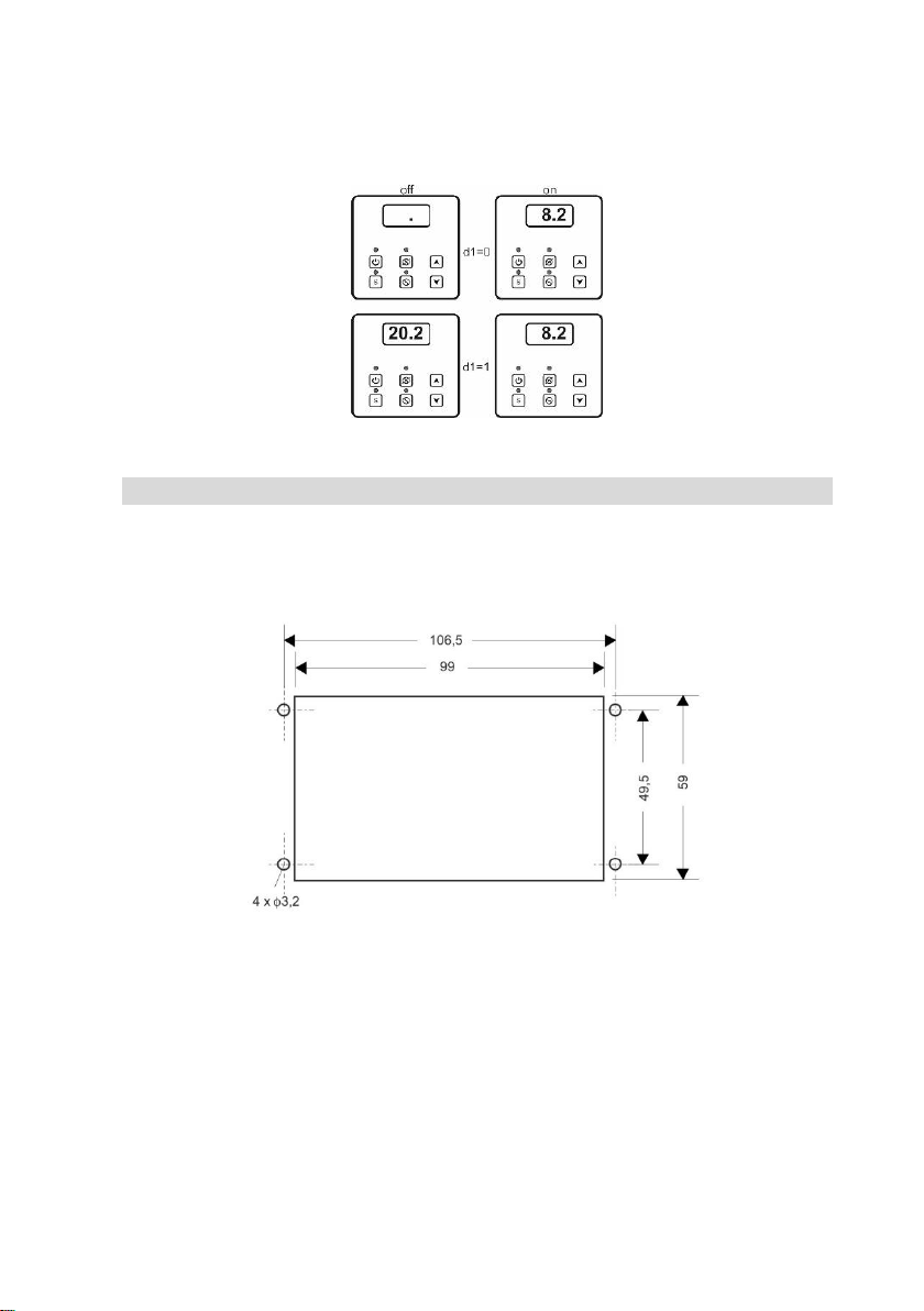
Page 4 of 13
If the regulator’s control operation is switched off, a dot is displayed on the regulator's
display (factory settings). By changing the parameter d1 (see 6. PROGRAMMING) from
the value 0 for value 1, when the regulator is switched off, the display will show the
current measured temperature.
4. SCHEME OF CONNECTION OF THE REGULATOR.
In order to connect the regulator to the device with which it is to be controlled,
the following should be done:
✓ prepare the hole in the refrigeration device to install the regulator
✓ place the regulator in the prepared hole and screw it in properly,
✓ place the temperature sensor inside the cooling chamber in the most convenient
place for temperature measurement and at the same time shielded from accidental
damage,
✓ connect the regulator to the outputs located on the rear wall of the casing, according
to the following scheme:
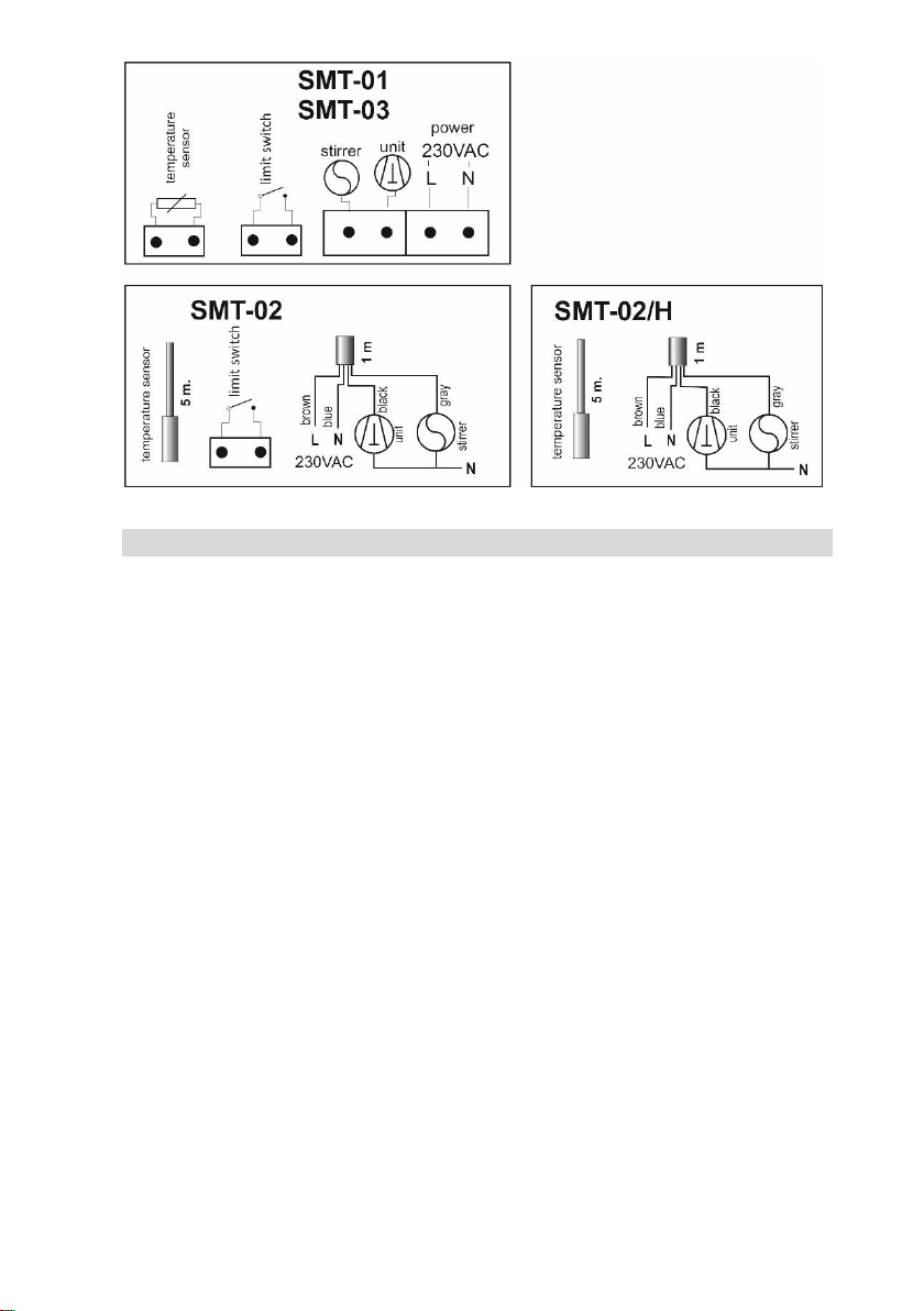
Page 5 of 13
5. REGULATOR FUNCTIONS.
The regulator is equipped with a number of functions that, together with the possibility
of creating your own program, enable adjusting the regulator's work to the individual
needs of the user. Some of the functions listed below are activated after the appropriate
programming of the regulator (see 6. PROGRAMMING and 9. SETTING TABLE).
1. Continuous temperature measurement function, regardless of whether
the regulator is on (regulator must be connected to the power supply) – parameter
d1 is set to 1.
2. The function of controlling the refrigeration system (unit), depending on the
measured temperature – parameter C9 is set to the value 0.
3. Light signaling function for switching on the cooling (heating) operation – blue LED
is on.
4. Control function of the heating system, depending on the measured temperature –
parameter C9 is set to 1.
5. The stirrer or fan control function enabling the implementation of the following
variants of this control – depending on the F0 parameter settings:
a. automatic operation:
− cyclic operation of the stirrer (fan), independent of the operating condition
of the unit (heating system),
− stirrer operates continuously during the operation of the unit, when the unit
is switched off, the stirrer goes into cyclic operation,
− stirrer (fan) works only when the unit (heating system) is switched on,
− continuous stirrer (fan) operation while the regulator's operation is on (main
application in dryers),

Page 6 of 13
− switched off stirrer (fan) operation,
b. operation triggered manually:
− switching on continuous stirrer (fan) operation, regardless of whether
the control operation of the regulator is switched on; in order to end
the stirrer (fan) operation, press the button [3],
− switching on the stirrer (fan) operation for a strictly defined time, regardless
of whether the control work of the regulator is switched on.
6. Blocking function of the stirrer and the unit when the flap of the milk cooler tank
opens (actuation of the limit switch) – parameter AF. In dryers it can be used to turn
off the fan, e.g. when the door is opened.
7. Defining the operation of the limit switch as negative or positive – parameter UU.
8. The unit operation supervision function, consisting in the possibility of setting
the maximum and minimum working time of the unit, as well as the minimum
standstill time of the unit – parameters E1 and E2.
9. The function of registering the maximum and minimum temperature values
throughout the regulator's working cycle. This function is connected with
the possibility of temporally delaying the recording of temperature data to the
regulator's memory since its activation – parameter AA.
10. The function of alarm signaling (visual and audible) of exceeding the set temperature
range – parameters HA and HE. This function is connected with the possibility
of delaying the time of switching on the alarm system of the regulator from
the moment of its activation.
11. Monitoring and signaling function of the damage to the temperature sensor – in such
case the letters ACU appear on the display.
12. Function of adjustable delay time for switching on the unit and stirrer after decay
and re-switching on the voltage – parameter dE.
6. PROGRAMMING.
In order to ensure the correct working cycle of the regulator, it is necessary to program
its operating parameters accordingly. By default, the controller is programmed
for standard operating conditions for the purpose of controlling the milk cooler.
In order to change the factory setting, enter the setting mode. This is done by holding
the button marked with the letter S for approx. 17 seconds. After entering the setting
mode UCO appears on the display. The next pressing of the S button confirms
the willingness to make changes. Then press the ▲ key to enter the access code and
confirm with the S button. After correct entry into the setting mode, the ▲ and ▼
buttons are used to select the desired parameter. The entry to the parameter settings is
made by pressing the S button. The change of the parameter value is made using the ▲
and ▼ buttons; for the change to be saved, confirm with the button S. The exit from

Page 7 of 13
the setting mode is made by setting the EE parameter and confirmation with the S button
or automatically after 17 seconds of inactivity. The following figure illustrates
the programming procedure:
7. THE REGULATOR’S WORK CYCLE.
When the regulator is connected to the mains and its operation is switched on with
the button [1], the regulator – after the delay set in parameter dE – goes to the control
phase.
The regulator controls two control circuits:
a. control circuit for the refrigeration (heating) unit;
b. control circuit for the stirrer’s (fan’s) motoreducer.
The work for the control settings of the refrigeration system will be discussed below.
ATTENTION
Parameter dE is the delay of switching on the unit and the stirrer after switching on
the regulator's work or after the supply voltage decay – default value is set to 5 sec.
7.1. Control of the refrigeration unit.
The temperature control value (within the range specified in parameters b1 and b2) is
set by pressing the buttons marked with the symbols ▲ and ▼, while short pressing any
of these buttons displays the currently set value, while only the next pressing causes
the change of this value. Transition on the display from reading the measured
temperature to the reading of the set control temperature is signaled by the flashing
of digits / numbers.

Page 8 of 13
The unit control in the cooling phase takes place depending on the temperature present
in the refrigeration chamber. The regulator can control the cooling temperature in the
range of -40 OC up to +120 OC. In order to limit the scope of the control so as to prevent
the user of the cooling device from setting the temperature outside this range, set the
proper parameters: b1 (limitation of the lower control temperature range) and b2
(limitation of the upper control temperature range).
ATTENTION
Temperatures specified in parameters b1 and b2 do not indicate control points
for switching off and switching on the operation of the unit.
Setting b1 = b2 blocks the possibility of changing the programmed temperature
by means of the ▲ and ▼ buttons. It is not allowed to set b1 > b2.
The change in the value of b1 or b2 can be blocked by the currently set control
temperature.
In the event of such a situation, change the control temperature settings and then
change parameters b1 and / or b2.
It is also important to set the control hysteresis correctly – parameter HI. The control
hysteresis is a parameter that determines the temperature difference at which
the switching off occurs and then the unit is switched on. For example, if the control
temperature is set to + 4 OC and hysteresis to 2 OC, then the unit will be switched off
after reaching 4 OC, while its re-activation will occur after the temperature has risen
to 4+2 = 6 OC.
The regulator allows to set the hysteresis of the control in the range of 0.2 OC to 10 OC,
every 0.2 OC.
ATTENTION
If the regulator is set in heating mode, the hysteresis operation has the opposite
character, i.e. the heating system is switched off after the temperature has dropped
below the set value, taking into account the value of the programmed hysteresis.
7.2. Control of the stirrer’s motoreducer.
The working status of the stirrer is signaled by two red LED (see 3. CONSTRUCTION):
− signaling of switching on the stirrer’s motoreducer [8],
− indication of the stirrer operation mode [7].
The regulator has two modes of stirrer operation, i.e. automatic or manual, which are
described in detail below.
7.2.1. Automatic stirrer operation.
In this mode, depending on the settings of parameters F0, E1 and E2, the stirrer may be
connected to the operation of the unit or completely independent of the operation
of the unit (see 9. TABLE OF SETTINGS).
The stireer operation setting in the automatic mode is signaled by the continuous
lighting of the red LED [7].

Page 9 of 13
The stirrer's operation can be switched off at any time by means of the [2] button
(see 3. CONSTRUCTION), except when the F0 parameter is set to 2 or 3.
Switching off the regulator by pressing the [1] button also turns off the stirrer operation.
7.2.2. Manually triggered stirrer operation.
The manual stirrer operation can be initiated by pressing the button marked by symbol
[3] (see 3. CONSTRUCTION); at this point, the automatic operation of the stirrer stops
and the manual operation starts. Manual operation of the stirrer is also possible when
the regulator is switched off (button [1]) or stirrer operation switched off (button [2]).
The manual operation of the stirrer is not interrupted when the regulator is switched off
manually by pressing the [1] button.
The setting of the stirrer operation in manual mode is signaled by a flashing red LED [7].
The stirrer operation in this mode can be interrupted at any time by pressing the button
again. The manual stirrer operation can take place in two variants, depending on the
CP parameter settings:
− setting the value 0 means continuous stirrer operation,
− setting the value >0 means that the stirrer works for the set number of minutes; after
the set time elapses, the manual operation of the stirrer is switched off.
ATTENTION
No light signaling of the stirrer operation [7] [8] when the regulator is switched off
means that the automatic stirrer operation has been switched off, at the same time
the manual operation has not been switched on.
8. ADDITIONAL FUNCTIONS.
Below, some specific functions of the regulator will be described, enabling the regulator
to be used for various applications.
8.1. Limit switch of the flap.
The regulator is equipped with the possibility of connecting the external limit switch
of the tank flap. The principle of operation of this input consists in immediately switching
off the stirrer's operation at the moment of shorting or opening of this input (depending
on the UU parameter setting), made by the connected limit switch of the flap. The return
of the stirrer operation (after being interrupted by the limit switch) follows after
the disappearance of the flap opening signal with a delay of 5 seconds.
At the same time, depending on the AF parameter settings made, it is possible to disable
the unit operation. The unit operation is switched off with a set delay in relation to the
opening signal of the flap, so that the momentary opening does not immediately stop
the operation of the unit. The unit returns to work after the flap opening signal
disappears, taking into account the programmed minimum standstill time of the unit.

Page 10 of 13
8.2. The function of registering the minimum and maximum temperatures.
The SMT regulator has the function of recording in its internal memory the values
of maximum and minimum temperatures that occur throughout the regulator's
operating cycle. This function makes it possible to check whether the milk is stored under
the correct temperature conditions.
When the device is switched on, after the end of the programmed delay (parameter AA
– see 9. TABLE OF SETTINGS), the temperature values are recorded to the regulator's
memory. The programmable delay time of enabling this function allows for pre-cooling
of the milk after the start of cooling and thus not taking into account the maximum
temperature when the device is started. This time should be selected by the user for the
type of tank and the actual operating conditions of the device.
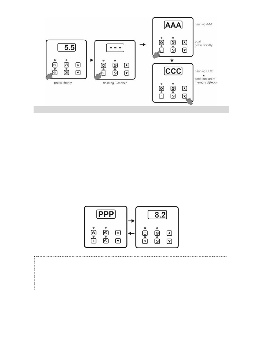
At any time, the user can read the maximum and minimum temperaturę values presently
available. The following figure illustrates reading:
ATTENTION
1. In the absence of entries of maximum and minimum temperatures in the regulator's
memory, the symbol --- is displayed.
2. Power supply loss causes the regulator's memory to be cleared.
At any time, you can manually delete the current maximum and minimum values.
The following figure illustrates manual memory erasing:
Page 11 of 13
8.3. The function of alarm signaling the exceeding of the correct temperature range.
The regulator has the function of signaling the exceeding of the set temperature range.
In order for the function to work properly, the appropriate temperature range must first
be programmed, this is: parameter A1 – temperature below which the alarm will be
activated and parameter A2 – temperature above which the alarm will be triggered
(see 9. TABLE OF SETTINGS).
The third parameter to be defined is the time delay of switching on the alarm function
from the moment the regulator’s operation is switched on – parameter AA. This delay
eliminates the triggering of an alarm in the initial cooling phase.
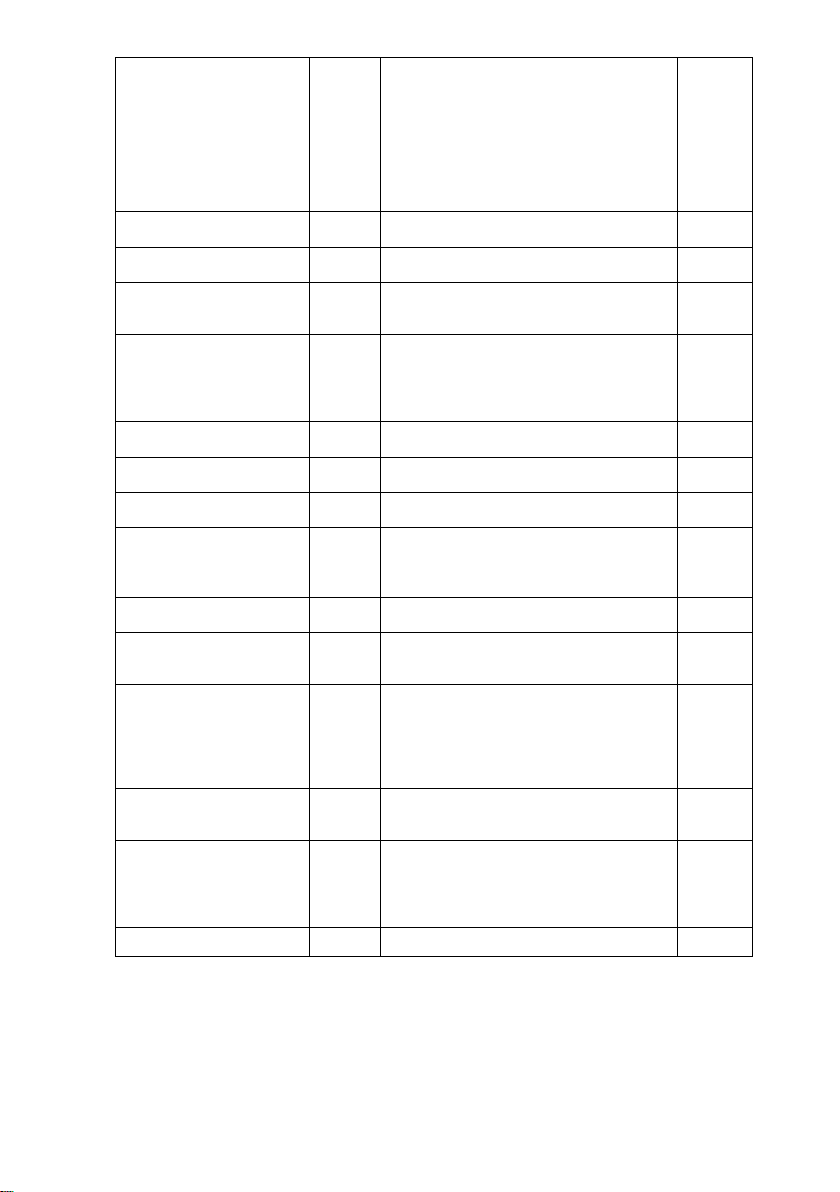
Exceeding the set temperature range is signaled visually and sound. In the event
of activation of the alarm, the buzzer is triggered cyclically every 1 minute for 5 seconds,
and at the same time letters PPP and the temperaturę value are displayed.
ATTENTION
The parameter AA is identical to the delay specified in the maximum and minimum
temperature recording function. In other words, the delay value set in the parameter
AA will be the same for recording max. and min. temperature and for parameters A1
and A2.
The audible alarm can be turned off by setting the HE parameter to 1 (see 9. TABLE
OF SETTINGS). In this case, exceeding the set temperature range is signaled only visually,
as shown in the figure above. The alarm system (audible and visual) can also be turned
off completely by changing the HA parameter to 1 (see 9. TABLE OF SETTINGS).

Page 12 of 13
8.4. Temperature sensor damage indication.
If the regulator etects damage to the temperature sensor, the letters ACU appears
on the display, and at the same time the audible alarm signal is activated. The operation
of the unit and the stirrer is interrupted until the failure is removed.
ATTENTION
Sensor damage indication also occurs if the range of temperatures measured by the
regulator is exceeded.
9. TABLE OF SEETINGS.
DESCRIPTION OF THE
PARAMETER
SYMBOL
SETTING RANGE
FACTORY
SETTING
accessing the settings
UC0
access code
1.2
regulator operation mode
C9
0 – cooling
1 – heating
0
limitation of the lower value
for the control temperature
range
b1
the possibility of setting the temperature from
-40 OC to +120 OC, every 1.0 OC
2 (OC)
limitation of the upper value
for the control temperature
range
b2
the possibility of setting the temperature from
-40 OC to +120 OC, every 1.0 OC
10 (OC)
control hysteresis
HI
the possibility of setting the temperature:
• from 0.2 OC to 10 OC, every 0.2 OC – for the
range from -10 OC to +100 OC and
• from 1.0 OC to 10 OC, every 1.0 OC – for the
range of <-10 OC and > + 100 OC
2 (OC)
minimum working time of the
unit
CA
0 – off
1 – on: the possibility of setting the time from
1 min. to 60 min., every 1 min.
0
maximum working time of the
unit
CC
0 – off
1 – on: the possibility of setting the time from
0,5 h to 9,5 h, every 0,5 h
0
minimum standstill time of
the unit (standby)
CF
0 – off
1 – on: the possibility of setting the time from
1 min. to 60 min., every 1 min.
0
time after which the unit is
turned off after the flap of the
milk tank
is opened
AF
0 – off
1 – on: the possibility of setting the time from 0,1
min. (6 s.) to 15 min., every 0,1 min. (6 s.)
0,1
(min.)
[= 6 s.]
stirrer operation mode
F0
0 – operation according to the times set in
the parameters E1 and E2, regardless of the
operation of the unit
1 – continuous operation while the unit is
running; when the unit is on standby, the stirrer
operates according to the times set in the
1
Page 13 of 13
parameters E1 and E2
2 – as in setting 1, but disabling with the
stirrer's working button causes its operation
only during the operation of the unit
3 – as in setting 1, but the button that disables
the stirrer operation is inactive
4 – continuous operation, regardless of the
operation of the unit and times set in the
parameters E1 and E2
standstill time of the stirrer
E1
the possibility of setting the time from 1 min.
to 60 min., every 1 min.
15 (min.)
working time of the stirrer
E2
the possibility of setting the time from 1 min.
to 60 min., every 1 min.
2 (min.)
manual stirrer operation
mode
CP
0 – continuous work
>0 – stirrer operation for a specified time in the
range of from 1 min. to 60 min., every 1 minute
5 (min.)
delay of registering of the
max. / min. values
of temperature and delay
of activation of the
temperature alarm
AA
the possibility of setting the time from 0 h to
24 h, every 0,1 h
2 (h)
lower temperature of the
alarm
A1
the possibility of setting the temperature from
-40 OC to +120 OC, every 1.0 OC
2 (OC)
upper temperature of the
alarm
A2
the possibility of setting the temperature from
-40 OC to +120 OC, every 1.0 OC
12 (OC)
sound of the alarm
HE
0 – on
1 – off
0
visual and sound alarm
of exceeding the set
temperature range
(parameters A1 and A2)
HA
0 – on
1 – off
0
scaling the control sensor**
CU
every 0,2 OC
scalable
value
setting the operation of the
limit switch of opening the
tank’s flap
UU
0 – closing the limit switch: raising the flap
1 – opening the limit switch: raising the flap
0
delay of switching on the unit
and the stirrer after
connecting
the regulator to the mains or
when power supply decay
occurs
dE
from 1 s. to 999 s., every 1 s.
5 (s.)
display status when the
control is switched off
d1
0 – the dot is displayed
1 – the currently measured temperature is
displayed
0
return to factory settings
FA
0
1 – after setting "1" and turning off the
regulator from the power supply, switching on
again restores the factory settings and the
parameter value goes back to "0"
0
leaving the settings
EE
** set at the manufacturing stage (do not change without obvious need)
 Loading...