

Page 1

Automatic
INSTRUCTION MANUAL
Drapery Opener
MODEL ZZCMlOl (CMlOl)
With receiving unit
MODEL ZZCM301 (CM301)
Without receiving unit
c
-
SPEC
Maximum
rod
length
20
I
F
ft.
I
CAT1
0
Maximum weight
60
N
S
of drapery
Ibs.
per mdtor
1I
\
a
7
Track speed of remote
50
ft. per minute
Minimum width
Single Double control unit
5
"
of
valance
8
"
Operating range
32.8
ft.
Page 2
WARNING:
Polarized
Plugs
To reduce the risk of electric shock, the motor has a polarized plug (one blade
a
than the other). This plug will fit in
fit fully in the outlet, reverse the plug. If
trician to install the proper outlet.
Rod
&
Motor
1
Rod
1 Motor
Rod
length
9
FT
18 FT
Assembly chart
Motor
Track
L
polarized outlet only one way. If the plug does not
it
still does not fit, contact a qualified elec
Do
not change the plug in any way.
Components
e9
ft track ZZOSTK (-WH)
0
Rod assy. ZZAR9 (with 32
carriers)
0
0
Motor model
ZZCM101 (CM101)
0
Remote controller:
ZZRClO (RC10)
0
Timer:
ZZCT10 (CT10)
ZZEC101 (EC101)
contains items listed
a
bove
.
:
Universal mounting brackets
ZZ3SWCB (-WH)
White end caps 2241 1001 -A
(For use with white track and
components.
0
9
ft track ZZOSTK (-WH)
0
Splice ZZ6SJ (-WH)
0
Rod assy. ZZAR20 (with 64
carriers
0
Universal mounting brackets
ZZ3SWCB (-WH)
0
White end caps 2241 1001
(For use with white track
and components.)
1
(5
per pack)
(5
per pack) x 2
is
x
2
-
A
wider
-
9
9
FT
Motor
2 Rods
2 Motors
7
18 FT
To
the following product labels, the letters
Track
Track
Motor
0
Motor model
ZZCM101 (CM101)+
ZZCM3Ol (CM301)
0
Remote controller:
ZZRC20 (RC20)
0
Timer:
ZZCT10 (CT10)
ZZEC201 (EC201)
contains items listed
above.
"ZZ"
:
may not be affixed:
ft track ZZOSTK (-WH)
0
Rod assy. ZZAR9 (with 32
carriers)
0
Universal mounting brackets
ZZ6DWCB (-WH)
0
White end caps 2241 1001-A
(For use with white track
and components.)
09
.Splice ZZ6SJ (-WH) x 2
0
Rod assy. ZZAR2O (with 64
carriers)
0
Universal mounting brackets
ZZGDWCB (-WH)
~Whiteendcaps ZZ411001-A
(For use with white track
and components.)
x
2
(5
ft track ZZOSTK (-WH) x 4
x
2
x
per pack)
x
2
(5
per pack) x 2
x
2
AR9,
2
AR20,
EC101, EC201, EC301, CM101, CM301, RC10, RC20, RC30, RC60, CT10, WSIO,
W S20, W S30.
2
Page 3
Cutting Track to Size
The
desired overall length of the rod should be determined and the aluminum track cut
according to the following equation prior to attaching the end and motor pulley housings.
Length
The purpose of the equation
of
aluminum track = overall length
3-314''
is
to offset for the length that the end and motor pulley
housings add to the overall length.
90
make
important for one
degree cuts and remove any burrs that may affect smooth operation; this
-
way applications.
Splicing Tracks
Center opening
less
5-1/4"
Total length
A
hack saw can be used to cut the track. Use care to
1-1
12"
is
most
For applications larger than
9',
two tracks must be spliced together using the supplied
splice. Tracks should be cut equal in length to ensure the splice will be centered in the
rod.
One-way
For one-way operations, cut only one track to adjust length.
Place
splice furthest away
from motor end.
NOTE
Insert tracks equally into
:
slice
butting them together. (Fig.
1
)
Fig.
1
Page 4
Rod
Assembly for Center Opening Applications
Allow yourself ample working area. Depending on the model of rod assembly and the
provided cable length, the end and motor pulley covers can be
assembly
1.
Remove twist
.
ties
from cable and care
-
as
far
as
20'
apart during
fully uncoil to prevent tangles.
2.
Loosen screws and remove securing
plates from each end of the temporary
(Fig.
track.
3.
Detach end and motor pulley housings
2)
Closing plates
A
Screwdriver
from temporary track.
4.
Remove closing plates from temporary
track. Discard temporary track.
5.
Stretch end and motor pulley housings
out to the fullest distance the cable will
allow. Make sure the cable
is
not tangled.
Position each closing plate near
its
re
Enb pulley housing
Temporary track
-
/
Motbr pulley housing
Fig.
2
spective pulley housing.
6.
Starting
at
the motor pulley housing
end, lay the cable into the aluminum
track about
making sure
it
4
"
twisted. While gently applying tension
(pulling) on the cable, insert the closing
3)
plate into the track. (Fig.
Be
keep the cable on the outside of the
4)
wheels. (Fig.
Attach the motor pulley
housing to the track. Make sure the
track is butted up to the stop inside the
cover. Repeat operation
again making sure wire
at
other end,
is
not twisted or
crossed. Reinstall securing plates to
motor pulley and end pulley housings.
is
not
sure to
Fig.
3
4
LWheei
of
closing
plate
Fig.
4
Page 5
NOTE
:
When inserting the closing plates into
the aluminum track, make sure the
cable stays on the outside of the wheels.
4)
(Fig.
the
in
housings. (Fig.
7.
Loosen the cable retaining screw on the
Also check that the cable rides
groove of the pulley in both
5)
top of the closing plate that has the
overlap arm. The screw
need
only be
loosened; be careful not to remove
completely. (Fig.
6)
it
Motor
I
/
\I
I
/
Pul:y
pulley
housing
\Aluminum
tt
.ac
\\
LCable
Fig.
I
k
8.
With pliers grab
all
pull
excess cable. (Fig.
keeping tension on the cable, re
the
screw. Check
sleeve
that
(A)
and gently
7)
-
the cable rides
in the groove of the pulley in both
If
housings.
7
and
8.
not, realign and repeat steps
Move the closing plate by hand
to make sure that the movement
smooth.
by:
cable
pulley wheel, or
any of these are the
If
it
is
not,
it
can be caused
(1)
The cable
is
not properly routed around the
is
twisted,
(3)
The cable
case,
make appropriate corrections.
(2)
is
Fig.
While
tighten
is
The
Fig.
not riding correctly in the groove of the pulley. If
1
'
Page 6
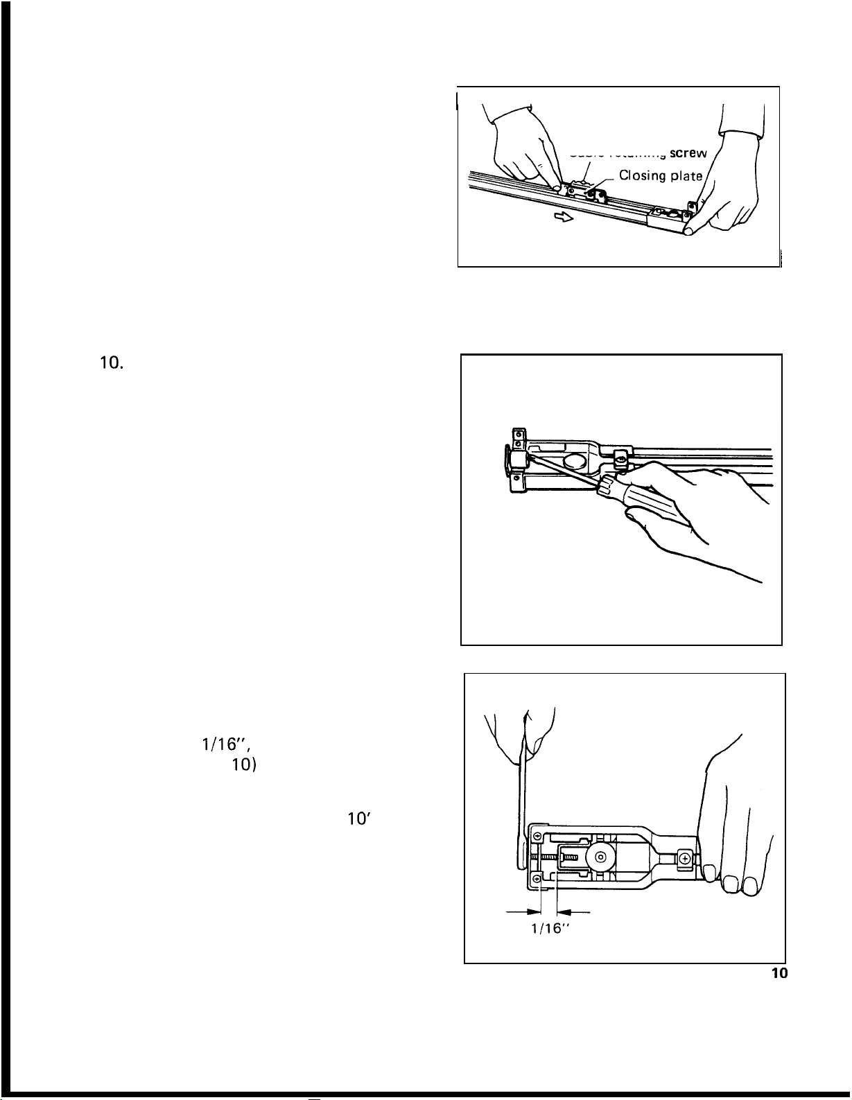
9.
Adjust center-position of draperies by
loosening the cable retaining screw on
the closing plate without the overlap
8)
The
arm. (Fig.
loosened; be careful not to remove it
completely. This will let the closing
plate slide on the cable allowing adjust
ment to achieve center (or desired
position). Some resistance will be felt
IO.
Using a screwdriver or the handle end
of
the provided wrench, lift out and
remove the temporary
the motor pulley housing and discard.
(Fig.
9)
screw need only be
steel
spacer from
as
I
-
\
Cable retaining scre
I
I
I
11.
With the provided wrench turn the ten
sion-adjusting bolt clockwise leaving
gap between tension plates of approxi
mately
nickel. (Fig.
NOTE
Rod lengths in
quire more tension
of the cable on the pulley wheels.
1/16",
:
or the thickness of
IO)
excess
of
IO'
to
prevent slipping
may
re
-
a
a
-
-
\
"V
Fig.
Fig.
9
10
Page 7
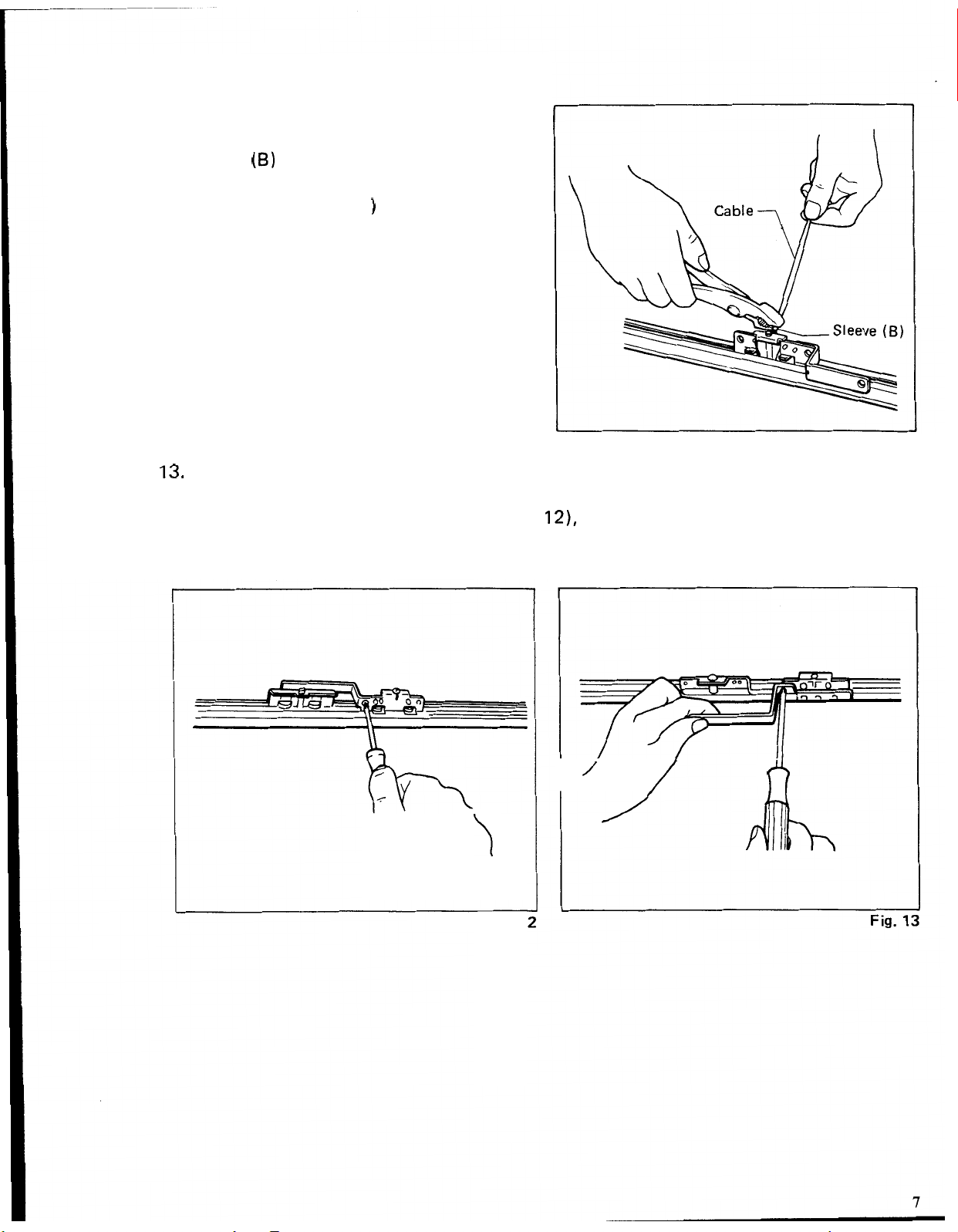
12.
After again making sure the movement
is
of the closing plates
sleeve
pliers, crimp the
excess cable. (Fig.
13.
The rod assembly comes
However,
fasten the arm to the closing plate (Fig.
same side, (on the same closing plate). (Fig.
so
(6)
up to the closing plate. With
sleeve
11
it
can just
as
to project toward the interior of the room once the rod has been mounted.
smooth, move
and cut off the
)
set
up to have the motor mounted on the right side of the rod.
as
easily be placed
at
the left side by removing the two screws that
12),
reversing the arm and reattaching to the
13)
The overlap arm should be attached
Fig.
11
\
>
Fig.
12
’/
n
Page 8

Rod
Assembly for One-way Operations
Allow yourself ample working area. Depending on the model of rod assembly and the
provided cable length, the end and motor pulley covers can be
assembly
.
as
far
as
20'
apart during
1. Follow steps
FOR CENTER OPENING APPLICA
1
-
5 of
ROD
ASSEMBLY
-
TIONS.
2.
Loosen and remove the screw from the
closing plate that does not have the
overlap arm. This will release the clos
ing plate from the cable. Discard closing
plate. (Fig. 14)
3.
Starting
4" making sure
at
the motor pulley housing end, lay the cable into the aluminum track about
it
is not twisted. While gently applying tension (pulling) on the cable,
insert the closing plate into the track. (Fig. 15) Be sure to keep the cable on the out
side of the wheels. (Fig. 16) Attach motor and end pulley housings to ends of track.
Make sure the track
is
butted up to the stops inside the housings. Reinstall securing
plates to motor pulley and end pulley housings.
Fig.
14
-
Cable
Alum
i
nu
m
track
Wheel
I
Fig.
15
&
1
of
closing plate
Fig.
16
8
Page 9

4.
Loosen the cable retaining screw on the
top of the remaining closing plate (with
overlap arm). The screw need only be
loosened; be careful not to remove
completely.
(Fig.
17)
it
sleeve
5.
With pliers gr
pull
all
excess cable. (Fig.
b
keeping tension on the cable, re
(A)
and gently
18)
While
-
tighten
the screw. Check that the cable rides in
the groove
ings.
and
If not, realign and repeat steps
5.
to make sure that the movement
smooth.
(1)
The cable
of
the pulley in both hous
4
Move the closing plate by hand
is
If
it
is
not,
it
can be caused by:
is
twisted,
(2)
The cable is
-
not properly routed around the pulley wheel, or
the groove of the pulley. If any
6.
Using a screwdriver or the handle end of
the provided wrench, lift out and re
move the temporary
steel
of
these are the
spacer from
-
the motor pulley housing and discard.
(Fig.
19)
I
I
Cable
(3)
case,
retaining
The cable
s
is
not riding correctly in
make appropriate corrections.
Fig.
Fig.
1
1,
Fig.
19
I
9
Page 10

7.
With the provided \ lrench turn the ten
sion-adjusting bolt clockwise leaving
gap between tension plates of approxi
mately
nickel. (Fig.
1/16",
20)
or the thickness of
-
a
-
a
NOTE
Rod lengths in excess of
quire more tension to prevent slipping
of the cable on the pulley wheels.
8.
After again making sure the movement
of the closing plate
sleeve
pliers, crimp the
excess cable. (Fig.
:
10'
is
smooth, move
(9)
up to the closing plate. With
sleeve
and cut off the
21)
may re
-
_I&
1
I1
6
"
Fig.
21
9.
The motor
the draperies will stack when open (right or left). The rod assembly comes
right stacking draperies. For left stacking draperies
lap arm on the closing plate. Remove the two screws that fasten the arm to the closing
plate (Fig.
motor to be on the left side of the track behind the draperies when open.
is
designed to be hidden behind the drapery stack. Determine on which side
set
it
is
necessary to reverse the over
22),
switch
it
to the opposite side and reattach. (Fig.
23)
This allows the
n
/7
Fig.
2:
Fig.
21
up for
Fig.
23
-
10
Page 11

Installation
Chart
Motor(s) may be attached on the right or left
01
rod, 1 motorsystem
02
rods, 2 motors system
using
the same components.
I
Double mounting bracket
I
I.
11
Page 12

Mounting
Rod
Supplied brackets will accommodate either wall or ceiling mount applications. Due to the
various building materials used in construction,
i.e.,
concrete, drywall or wood, we do not
supply fasteners. Your local hardware store can help you in choosing the proper fastener
for your needs.
1.
Attach appropriate brackets (ceiling or wall) to the rod approximately every 24".
Make sure to place
a
bracket close to each end since this
is
where the most weight
is
placed when the draperies are open.
NOTE
:
When mounting rod to wall or ceiling allow extra space to accommodate for the neces
sary floor and track clearance. Typical allowance will be 1-1/2" to 2" greater than
drapery length. This will prevent the draperies from dragging across the floor while
allowing the draperies to be hung below the rod for smooth operation.
2.
Position rod in desired location and
mark bracket mounting holes on wall or
ceiling depending on your specific appli
cation.
ing dimensions.) It
(See
Fig. 24 for bracket mount
is
important for
-
-
NSTALLATION CHART:
in the right
or
left
using
DOUBLE CEILING MOUNT APPLICATION
Motorts) may be attached
the same components.
proper operation to mount the rod
straight and
level.
ceiling will not be straight or true.
mount brackets have the ability to
adjust for this. Once the rod
loosen the screw that attaches the
Many times walls and
Wall
is
up,
ceil
-
I
Minimum Mlnlmum
DOUBLE WALL MOUNT APPLICATION
ing clip to the wall bracket. This will
allow the rod to relax to
its
natural
straight shape. Retighten the screws. In
case
the
of ceiling mount,
it
may be
necessary to place shims between the
bracket and ceiling in order to make the
rod straight and
3.
Detach brackets from rod, drill marked
holes to
size
level.
for the fasteners chosen
and attach brackets.
SINGLE WALL MOUNT
1
9/16"
-
SINGLE CEILING MOUNT
4
t
I
""
Minimum
-
12
Fig.
24
Page 13

4.
Starting
rod into brackets. (Fig.
fully attach rod into bracket; a snap or
click can be felt and heard when proper
ly engaged.
at
the center of the rod, snap
25)
Be
sure
to
-
/
Fig.
2!
Loading
After installing the rod, remove securing
plates and load carriers
ends of the rod. In the
applications, carriers would be loaded from
motor pulley housing end only. Load the
proper amount
specific drapery
cable on outside
carriers. Reinstall securing plates
time.
Stop
The stop
position options for attaching draperies.
Tighten securing plate
Leave motor pulley securing plate (with re
turn arms and extra pinning holes) loose
since
to attach the motor. After motor is
tached to the motor pulley housing, slide
the securing plate back until
over rubber section and tighten.
Carriers
(Fig.
26)
into both
case
of
one-way
of
carriers based on your
size.
Be
careful to keep
of
wheels when loading
at
(Optional)
is
designed to
it
must be slid down the track in order
give
more pinning
at
end pulley only.
it
is
centered
this
at
-
-
\
\
\\
Fig.
26
I
Fig.
2'
13
Page 14

Attaching
Motor
One Motor, One
Track
System
With rod mounted to either wall or ceiling, attach the motor to the rod.
1.
Holding the motor
at
45 degree angle to
the track, push down on the lever on
the
motor, insert the shaft into the hole
the
in
parallel to the track. (Fig.
motor gear and turn the motor
28)
Release
the lever and the motor will lock into
the motor pulley housing. Without
pushing the lever, gently try to twist the
motor to ensure
(Fig.
29)
some play will be
it
is
securely attached.
felt,
however
the motor should not release.
2.
Slide back the under cover from the
motor to expose the female modular
1
connecting ports.
3.
Connect timer to modular port labeled
"
Timer". The timer comes with Velcro
We
for attaching to the wall.
mend
draperies where
TIMER
it
be put behind the stack of the
it
will out of view.
section for instructions on how
recom
-
See
to program.
otor
pulley
housing
Fig.
28
4. Return under cover to original position.
5. Position the infrared receiving eye
as
to have the black part facing the
so
room without any obstructions.
6.
Hang draperies. Remember to adjust pins
the bottom of the rod.
7.
Plug motor into standard
NOTE
:
The infrared receiving eye
120 V polarized receptacle.
is
designed to receive the signal through most draperies and be
hidden from view. However, some black
these
cases
the receiving eye must be exposed.
Fig.
so
the top of the draperies ride just below
-
out type draperies can impede the signal.
29
In
14
Page 15

Two Motors, Two Tracks System
1.
Follow step 1 of
TRACK
closest to window.
SYSTEM
ONE
MOTOR,
starting with rod
ONE
~
,
ZZCM301
(without receiving
(No.2)
unit)
NOTE
With the two motor system (over and
under draperies), the
(ZZCNllOl)
most rod (room side), and the "kid
motor should be on the rod closest to
the window. (Fig.
2.
Slide back the under cover from both
motors to expose the female modular
connecting ports.
3.
Connect provided modular connecting
wire from port labeled number
the
(Fig.
tion clips on the side of the motor. (Fig.
32)
and prevent the wire from interfering
with the draperies.
:
"
parent" motor
should be on
the
30)
"2"
"
parent" motor to the "kid" motor.
31)
Route wire through the reten
This will
give
a
more finished
inner
on
look
"
-
~
-
Receiving nut
Inside
ZZCMIOI
(with receiving
ZZCM301
ZZCMIOI
(No.
1)
unit)
Fig.
(No.
(No.
30
2)
1)
4.
Connect timer to modular port labeled
"
Timer" on "parent" motor. The timer
comes with Velcro for attaching to the
wall.
the stack of
out of view.
instructions on how to program.
5.
6.
Position the infrared receiving eye
to
without any obstructions.
7.
Hang draperies. Remember to adjust
pins
below the bottom of the rod.
8.
NOTE
The infrared receiving eye
hidden from view. However, some black out
these
We
recommend
the
See
Reinstall under cover on both motors.
have
the black part facing
so
the top of the draperies ride just
Plug motors into standard
:
cases
the receiving eye must be exposed.
it
be put behind
draperies where
TIMER
section for
the
120
V polarized receptacle.
is
designed to receive the signal throuqh most draperies and be
it
will
so
room
as
'
Fig.
Fig.
-
type draperies can impede the signal. In
31
I
32
15
Page 16

Remote control unit
Point the remote control unit in the direction of the receiving unit. The operating range
is
of the remote control unit
Button indicated above opens the drapery.
Button indicated above closes the drapery.
4
I
STOP
Button indicated above stops the drapery
in any position.
Push button slightly. One push of the
button
drapery fully open or fully closed, there
is
no need to operate the
because
drapery
I
is
sufficient. When you want the
it
will automatically stop when the
is
fully open or fully closed.
32.8 ft.
button,
ORAPERY REMOTE
CONTROLLER
E10
STOP
88
STOP
on
NOTE
When the motor
the button to move in the same direction,
In
ZZCM301
control unit, respectively
the
:
is
stopped
case
of ZZCMlOl (CM101) + ZZCM301 (CM301
(CM301) (No. 2) can be operated by No. 1 and No. 2 buttons on the remote
at
the fully open or fully closed position, and you then push
.
ZZCM301 (CM301)
(NO.
2)
v
A*
LZZCM1O1 (CM101)
(No.
1)
it
will not operate.
),
ZZCMlOl (CM101)
(No.
1) and
16
Page 17

24
Hour
Timer
-
4
Memory
Timer Disl )lay
Functions
I
TIME
!
ON/OFF
E3
CAUTION
.Do not install in locations where temperatures exceed 50°C
sunlight can strike the timer.
The LCD (liquid crystal display) can be damaged by excessive heat.
Avoid locations where temperatures may become excessively low. LCD response time
may be slowed or the time may become inoperative. These low temperature symptoms
are not permanent. Normal functions will return after the timer warms up.
:
Time
I
Timer
OpedClose Button
Memory Clear Button
Memory Display Button
Minute
Hour
Set
Button
ON/OFF
Set
Button
Set
Button
(122°F)
Button
or where direct
0
Do not drop or impact the timer, Do not attempt to disassemble or damage may result.
17
Page 18

Installing timer
Connect the timer cord to the connecting jack marked "TIMER" on
receiving unit). Use
the appropriate location.
Setting
Entire display flickers when the power
comes
.When
the
dicators light up steadily. The display will
return to the flickering status after about
15
.Adjustment to the correct present time
can be made using the
tons. Adjusting past
advance the
mode, the colon
and minute digits will keep lighting up
steadily.
pressed and held, the "Hour" or "Minute
indicator will continue to advance.
for
present time
ON.
the
-1
"
Hour", "Minute" and "AM-PM" in
seconds, if
"
If
either
Velcro tape provided on the back of
button
left
as
is.
Hour" indicator. During this
If : I'
the
is
pushed, only
jHi
and
/MI
60
minutes does not
between the hour
(HI
or
(Mi
button
but
-
-
is
"
the
timer to attach the timer
Time Adjust Mode
1
No.
1
I
1
motor (with
+
!
In 15seconds
i
In 15 seconds
to
0
About
the
automatically. During the "Present Time
mode, the colon
.To
exact moment when the minute changes. The time will begin from that moment from
"00"
0
After setting the time,
button to change modes from the "Present Time" to the "Time Adjust". Then adjust
the time according to the previous instructions.
15
seconds after setting the time,
display will turn to the "Present Time
''
:
If
will keep flickering.
adjust the time to the nearest second, push the button and release
seconds.
if
you wish to readjust the present time, first push the
"
"
Present Time Mode
it
at
I
TIME
the
18
Page 19

Setting
for
open/close time
*Push
the
open/close indicator will flicker. This
indicates that the timer
"
The open/close indicator can be changed
to
merely pushing the
Adjust
by using the and
ture
display after adjustment for drapery
opening
@By
more, the
flicker. Follow the previous procedures to
set
and
the
F]
"
Timer
Timer
Set
"
"
open mode" or "close mode" by
the "open" time
at
right shows an example of the
at
7
:
pushing the
open/close time in memories
4.
button to change to
Set
"
mode. The left side
is
now in the
mode for memory
open/close button.
or
"
close" time
/Mi
buttons. The pic
00
a.m.
-1
open/close indicator will
button once
No.
I
No.
2,
1.
-
HM
""
3
elf you wish to erase the memory, push
the-] button to flicker the desired
memory
IhA/c]
open/close indicator will disappear from
the display.
No.
1,
2,
3
or
4.
Then push the
button to erase. The appropriate
I
-:
-\I/.
I
19
Page 20

Timer function
To actuate the timer, push the
button. The open/close indicator will
appear.
0
To
turn the timer off, push the
button again. The open/close indicator
will disappear from the display.
Confirming open/close time
1
ON/OFF
ONIOFF
,
-_
ON’OFF
r
AM
I
I
I
I
-,\
I
/
=
.
-11
L7.T-I
I
9
.
tzf
Timer Function
1-1
Timer Function
(OFF)
(ON)
To confirm the open/close time, push the
button, the
whenever necessary.
Note
:
Memories
programmed
necessarily sequential
The operating time for opening or closure
tion time, remote control operation
0
If the motor
reprogram memory
Maintenance
Wipe the timer with a soft, dry cloth. Do not use alcohol, benzene or thinner type pro
ducts, or damage to the timer may result.
set
times for memory
No.
1
-
4
need not relate to the exact sequence
into the timer. Memories can be
I
y
.
is
unplugged or electric failure happens, memory will be lost. You must
as
previously explained. The present time also needs to be re-set.
No.
[MEMO]
1,
2,
is
isnot possible.
button. Each time you push
3
and 4 will be displayed.
set
approximately 6 seconds. During this opera
them,
Reset
of
functions that you have
independently of each other: not
the memory
-
-
20
Page 21

OPT
ION A L
ACC
E
SSO
R
I
ES
WALL SWITCH
Wall
switch can only
Model
for
ZZWSIO (WSIO)
one
motor
i
(For
class
be
used
2
wiring only)
in conjunction with ZZCM101 (CM101).
Model
for
ZZWS20 (WS20)
two motors.
21
Page 22

MAINTENANCE
Test
operat
After assembling the complete system, connect to the power supply. Test the manual
and automatic operation to be sure the system functions properly. In
check the following
ion
"
Trouble Shooting Chart".
case
of a problem,
Trouble
Problem
Remote control unit
does not operate.
Motor does not stop
matically
fully closed positions,
Can operate
(No. 1 ) but cannot operate
ZZCM301 (CM301) (No.
ZZCM301 (CM301)
Drapery automatically stops
without pushing button
before drapery
or fully closed.
Cannot open and close Assembly of drapery track
drapery
at
fully open and
ZZCM101 (CM101)
~~
by hand.
auto-
(No.
is
fully open
2)
or
3).
Power plug
properly. power receptacle properly.
Battery in remote control Replace battery in remote
unit
Receiving unit
Not enough tension on the
cable. by turning tension adjusting
Cord on motor (with receiv-
ing unit)
properly.
Interference with movement
of d rapery
is
incorrect. to instructions in this manual.
Shooting
Cause Solution
is
not engaged Plug power supply cord into
is
dead. control unit.
is
not ccnnected
Chart
is
obstructed. Remove interferring object.
.
Increase tension of the cable
hex. bolt.
Reconnect cord accroding to
instructions in this manual.
Remove object which restricts
drapery.
-
assemble track according
Re
I
maintain product SAFETY and RELIABILITY, repairs should
To
be performed by
Makita Authorized or Factory Service Centers, always using Makita replacement parts.
22
Page 23

..............................................
*
*
*
*
*
*
*
*
*
*
*
*
*
*
*
*
*
*
*
*
*
*
*
*
*
*
*
*
*
*
*
*
MAKITA LIMITED THREE YEAR WARRANTY
Warranty Policy
Every Makita motor is thoroughly inspected and tested before leaving the factory. It is warranted to
of
be free
of
original purchase. Should any trouble develop during this three-year period, return the COMPLETE
motor, freight prepaid,
the trouble is caused by defective workmanship or material, Makita will repair (or at our option, replace)
without charge.
This Warranty does not apply where:
repairs have been made or attempted by others:
repairs are required because of normal wear and tear:
The motor has been abused, misused or improperly maintained;
*alterations have been made to the motor.
.The battery has not been charged immediately after purchase.
IN NO EVENT SHALL MAKITA BE LIABLE FOR ANY INDIRECT, INCIDENTAL
DAMAGES FROM THE SALE
DURING AND AFTER THE TERM OF THIS WARRANTY.
MAKITA DISCLAIMS LIABILITY FOR ANY IMPLIED WARRANTIES, INCLUDING IMPLIED WAR
RANTIES OF “MERCHANTABILITY” AND “FITNESS
THREE
This Warranty gives you specific legal rights, and you may also have other rights which vary from
state to state. Some states do not allow the exclusion or limitation of incidental or consequential
damages,
on how long an implied warranty lasts,
defects from workmanship and materials for the period of THREE YEAR from the date
to
one of Makita’s Factory or Authorized Service Centers.
OR
USE OF THE PRODUCT. THIS DISCLAIMER APPLIES BOTH
FOR
A SPECIFIC PURPOSE,” AFTER THE
-
YEAR TERM OF THIS WARRANTY.
so
the above limitation or exclusion may not apply to you. Some states do not allow limitation
so
the above limitation may not apply to you.
If
inspection shows
OR
CONSEQUENTIAL
*
*
*
*
*
*
*
*
*
*
*
*
*
*
*
*
*
*
*
*
*
*
*
*
-
*
*
*
*
*
8
*
*
...............................................
 Loading...