

Makita XAG21, XAG20 Instruction Manual
INSTRUCTION MANUAL
MANUAL DE INSTRUCCIONES
Cordless Angle Grinder
Esmeriladora Angular
Inalámbrica
XAG20
XAG21
IMPORTANT: Read Before Using.
IMPORTANTE: Lea antes de usar.

2 ENGLISH
ENGLISH (Original instructions)
SPECIFICATIONS
Model: XAG20 XAG21
Wheel diameter 125 mm (5″) *
Max. wheel thickness 6.4 mm (1/4″)
Spindle thread 15.88 mm (5/8″)
Rated speed (n) 8,500 /min
Overall length 382 mm (15″)
Rated voltage D.C. 18 V
Net weight 2.4 - 3.1 kg (5.2 - 6.7 lbs) 2.4 - 3.1 kg (5.3 - 6.8 lbs)
Electric brake
Wireless activation function -
* If you install optional wheel guard indicated as 4-1/2″ on the tool, 115mm (4-1/2″) wheels can be used.
• Due to our continuing program of research and development, the specications herein are subject to change
without notice.
• Specications may differ from country to country.
• The weight may differ depending on the attachment(s), including the battery cartridge. The lightest and heaviest combination, according to EPTA-Procedure 01/2014, are shown in the table.
Applicable battery cartridge
BL1815N / BL1820B / BL1830 / BL1830B / BL1840B / BL1850B / BL1860B
• Some of the battery cartridges listed above may not be available depending on your region of residence.
WARNING: Only use the battery cartridges listed above. Use of any other battery cartridges may cause
injury and/or re.
SAFETY WARNINGS
General power tool safety warnings
WARNING: Read all safety warnings, instruc-
tions, illustrations and specications provided
with this power tool. Failure to follow all instructions
listed below may result in electric shock, re and/or
serious injury.
Save all warnings and instructions for future reference.
The term "power tool" in the warnings refers to your
mains-operated (corded) power tool or BATTERYoperated (cordless) power tool.
Work area safety
1. Keep work area clean and well lit. Cluttered or
dark areas invite accidents.
2. Do not operate power tools in explosive atmo-
spheres, such as in the presence of ammable
liquids, gases or dust. Power tools create sparks
which may ignite the dust or fumes.
3. Keep children and bystanders away while
operating a power tool. Distractions can cause
you to lose control.
Electrical Safety
1.
Power tool plugs must match the outlet. Never modify
the plug in any way. Do not use any adapter plugs
with earthed (grounded) power tools. Unmodied plugs
and matching outlets will reduce risk of electric shock.
2. Avoid body contact with earthed or grounded
surfaces, such as pipes, radiators, ranges and
refrigerators. There is an increased risk of elec-
tric shock if your body is earthed or grounded.
3. Do not expose power tools to rain or wet conditions. Water entering a power tool will increase
the risk of electric shock.
4. Do not abuse the cord. Never use the cord for
carrying, pulling or unplugging the power tool.
Keep cord away from heat, oil, sharp edges
or moving parts. Damaged or entangled cords
increase the risk of electric shock.
5.
When operating a power tool outdoors, use an
extension cord suitable for outdoor use. Use of a cord
suitable for outdoor use reduces the risk of electric shock.
6. If operating a power tool in a damp location is
unavoidable, use a ground fault circuit interrupter (GFCI) protected supply. Use of a GFCI
reduces the risk of electric shock.
7.
Power tools can produce electromagnetic elds
(EMF) that are not harmful to the user. However,
users of pacemakers and other similar medical
devices should contact the maker of their device and/
or doctor for advice before operating this power tool.

3 ENGLISH
Personal Safety
1. Stay alert, watch what you are doing and use
common sense when operating a power tool.
Do not use a power tool while you are tired or
under the inuence of drugs, alcohol or medication. A moment of inattention while operating
power tools may result in serious personal injury.
2. Use personal protective equipment. Always
wear eye protection. Protective equipment such
as dust mask, non-skid safety shoes, hard hat, or
hearing protection used for appropriate conditions
will reduce personal injuries.
3. Prevent unintentional starting. Ensure the
switch is in the off-position before connecting
to power source and/or BATTERY pack, picking up or carrying the tool. Carrying power tools
with your nger on the switch or energising power
tools that have the switch on invites accidents.
4. Remove any adjusting key or wrench before
turning the power tool on. A wrench or a key left
attached to a rotating part of the power tool may
result in personal injury.
5. Do not overreach. Keep proper footing and
balance at all times. This enables better control
of the power tool in unexpected situations.
6. Dress properly. Do not wear loose clothing or
jewellery. Keep your hair, clothing and gloves
away from moving parts. Loose clothes, jewel-
lery or long hair can be caught in moving parts.
7. If devices are provided for the connection of
dust extraction and collection facilities, ensure
these are connected and properly used. Use of
dust collection can reduce dust-related hazards.
8.
Do not let familiarity gained from frequent use
of tools allow you to become complacent and
ignore tool safety principles. A careless action can
cause severe injury within a fraction of a second.
9. Always wear protective goggles to protect
your eyes from injury when using power tools.
The goggles must comply with ANSI Z87.1 in
the USA.
It is an employer's responsibility to enforce
the use of appropriate safety protective equipments by the tool operators and by other persons in the immediate working area.
Power tool use and care
1. Do not force the power tool. Use the correct
power tool for your application. The correct
power tool will do the job better and safer at the
rate for which it was designed.
2. Do not use the power tool if the switch does
not turn it on and off. Any power tool that cannot
be controlled with the switch is dangerous and
must be repaired.
3.
Disconnect the plug from the power source and/
or remove the BATTERY pack, if detachable,
from the power tool before making any adjustments, changing accessories, or storing power
tools. Such preventive safety measures reduce the
risk of starting the power tool accidentally.
4. Store idle power tools out of the reach of children and do not allow persons unfamiliar with
the power tool or these instructions to operate
the power tool. Power tools are dangerous in the
hands of untrained users.
5.
Maintain power tools and accessories. Check for
misalignment or binding of moving parts, breakage of parts and any other condition that may
affect the power tool’s operation. If damaged, have
the power tool repaired before use. Many accidents
are caused by poorly maintained power tools.
6. Keep cutting tools sharp and clean. Properly
maintained cutting tools with sharp cutting edges
are less likely to bind and are easier to control.
7. Use the power tool, accessories and tool bits
etc. in accordance with these instructions, taking into account the working conditions and
the work to be performed. Use of the power tool
for operations different from those intended could
result in a hazardous situation.
8.
Keep handles and grasping surfaces dry, clean
and free from oil and grease. Slippery handles
and grasping surfaces do not allow for safe handling
and control of the tool in unexpected situations.
9. When using the tool, do not wear cloth work
gloves which may be entangled. The entanglement of cloth work gloves in the moving parts may
result in personal injury.
BATTERY tool use and care
1. Recharge only with the charger specied by
the manufacturer. A charger that is suitable for
one type of BATTERY pack may create a risk of
re when used with another BATTERY pack.
2.
Use power tools only with specically designated BATTERY packs. Use of any other
BATTERY packs may create a risk of injury and re.
3.
When BATTERY pack is not in use, keep it
away from other metal objects, like paper clips,
coins, keys, nails, screws or other small metal
objects, that can make a connection from one
terminal to another. Shorting the BATTERY termi-
nals together may cause burns or a re.
4.
Under abusive conditions, liquid may be ejected
from the BATTERY; avoid contact. If contact acci-
dentally occurs, ush with water. If liquid contacts
eyes, additionally seek medical help. Liquid ejected
from the BATTERY may cause irritation or burns.
5. Do not use a BATTERY pack or tool that is
damaged or modied. Damaged or modied
batteries may exhibit unpredictable behaviour
resulting in re, EXPLOSION or risk of injury.
6. Do not expose a BATTERY pack or tool to re
or excessive temperature. Exposure to re or
temperature above 130 °C may cause explosion.
7. Follow all charging instructions and do not
charge the BATTERY pack or tool outside the
temperature range specied in the instructions. Charging improperly or at temperatures
outside the specied range may damage the
BATTERY and increase the risk of re.
Service
1.
Have your power tool serviced by a qualied repair
person using only identical replacement parts. This
will ensure that the safety of the power tool is maintained.
2.
Never service damaged BATTERY packs. Service
of BATTERY packs should only be performed by the
manufacturer or authorized service providers.
3. Follow instruction for lubricating and chang-
ing accessories.

4 ENGLISH
Cordless grinder safety warnings
Safety Warnings Common for Grinding, Sanding,
Wire Brushing, or Abrasive Cutting-Off Operations:
1. This power tool is intended to function as a
grinder, sander, wire brush or cut-off tool.
Read all safety warnings, instructions, illus-
trations and specications provided with this
power tool. Failure to follow all instructions listed
below may result in electric shock, re and/or
serious injury.
2.
Operations such as polishing are not recommended to be performed with this power tool.
Operations for which the power tool was not designed
may create a hazard and cause personal injury.
3. Do not use accessories which are not speci-
cally designed and recommended by the tool
manufacturer. Just because the accessory can
be attached to your power tool, it does not assure
safe operation.
4. The rated speed of the accessory must be at
least equal to the maximum speed marked on
the power tool. Accessories running faster than
their rated speed can break and y apart.
5. The outside diameter and the thickness of your
accessory must be within the capacity rating
of your power tool. Incorrectly sized accessories
cannot be adequately guarded or controlled.
6.
Threaded mounting of accessories must match
the grinder spindle thread. For accessories
mounted by anges, the arbour hole of the
accessory must t the locating diameter of the
ange. Accessories that do not match the mounting
hardware of the power tool will run out of balance,
vibrate excessively and may cause loss of control.
7.
Do not use a damaged accessory. Before each
use inspect the accessory such as abrasive
wheels for chips and cracks, backing pad for
cracks, tear or excess wear, wire brush for loose
or cracked wires. If power tool or accessory
is dropped, inspect for damage or install an
undamaged accessory. After inspecting and
installing an accessory, position yourself and
bystanders away from the plane of the rotating
accessory and run the power tool at maximum
no-load speed for one minute. Damaged acces-
sories will normally break apart during this test time.
8. Wear personal protective equipment.
Depending on application, use face shield,
safety goggles or safety glasses. As appropriate, wear dust mask, hearing protectors,
gloves and workshop apron capable of stopping small abrasive or workpiece fragments.
The eye protection must be capable of stopping
ying debris generated by various operations.
The dust mask or respirator must be capable of
ltrating particles generated by your operation.
Prolonged exposure to high intensity noise may
cause hearing loss.
9. Keep bystanders a safe distance away from
work area. Anyone entering the work area
must wear personal protective equipment.
Fragments of workpiece or of a broken accessory
may y away and cause injury beyond immediate
area of operation.
10. Hold the power tool by insulated gripping
surfaces only, when performing an operation
where the cutting tool may contact hidden
wiring. Contact with a "live" wire will also make
exposed metal parts of the power tool "live" and
could give the operator an electric shock.
11. Never lay the power tool down until the acces-
sory has come to a complete stop. The spinning
accessory may grab the surface and pull the
power tool out of your control.
12. Do not run the power tool while carrying it at
your side. Accidental contact with the spinning
accessory could snag your clothing, pulling the
accessory into your body.
13. Regularly clean the power tool’s air vents. The
motor’s fan will draw the dust inside the housing
and excessive accumulation of powdered metal
may cause electrical hazards.
14. Do not operate the power tool near ammable
materials. Sparks could ignite these materials.
15. Do not use accessories that require liquid
coolants. Using water or other liquid coolants
may result in electrocution or shock.
Kickback and Related Warnings
Kickback is a sudden reaction to a pinched or snagged
rotating wheel, backing pad, brush or any other accessory. Pinching or snagging causes rapid stalling of the
rotating accessory which in turn causes the uncon-
trolled power tool to be forced in the direction opposite
of the accessory’s rotation at the point of the binding.
For example, if an abrasive wheel is snagged or
pinched by the workpiece, the edge of the wheel that is
entering into the pinch point can dig into the surface of
the material causing the wheel to climb out or kick out.
The wheel may either jump toward or away from the
operator, depending on direction of the wheel’s move-
ment at the point of pinching. Abrasive wheels may also
break under these conditions.
Kickback is the result of power tool misuse and/or
incorrect operating procedures or conditions and can be
avoided by taking proper precautions as given below.
1. Maintain a rm grip on the power tool and
position your body and arm to allow you to
resist kickback forces. Always use auxiliary
handle, if provided, for maximum control over
kickback or torque reaction during start-up.
The operator can control torque reactions or kickback forces, if proper precautions are taken.
2. Never place your hand near the rotating acces-
sory. Accessory may kickback over your hand.
3. Do not position your body in the area where
power tool will move if kickback occurs.
Kickback will propel the tool in direction opposite
to the wheel’s movement at the point of snagging.
4. Use special care when working corners, sharp
edges etc. Avoid bouncing and snagging the
accessory. Corners, sharp edges or bouncing
have a tendency to snag the rotating accessory
and cause loss of control or kickback.
5. Do not attach a saw chain woodcarving blade
or toothed saw blade. Such blades create frequent kickback and loss of control.

5 ENGLISH
Safety Warnings Specic for Grinding and Abrasive
Cutting-Off Operations:
1. Use only wheel types that are recommended
for your power tool and the specic guard
designed for the selected wheel. Wheels for
which the power tool was not designed cannot be
adequately guarded and are unsafe.
2. The grinding surface of centre depressed
wheels must be mounted below the plane of
the guard lip. An improperly mounted wheel that
projects through the plane of the guard lip cannot
be adequately protected.
3.
The guard must be securely attached to the
power tool and positioned for maximum safety,
so the least amount of wheel is exposed towards
the operator. The guard helps to protect the opera-
tor from broken wheel fragments, accidental contact
with wheel and sparks that could ignite clothing.
4.
Wheels must be used only for recommended
applications. For example: do not grind with the
side of cut-off wheel. Abrasive cut-off wheels are
intended for peripheral grinding, side forces applied
to these wheels may cause them to shatter.
5. Always use undamaged wheel anges that are
of correct size and shape for your selected
wheel. Proper wheel anges support the wheel
thus reducing the possibility of wheel breakage.
Flanges for cut-off wheels may be different from
grinding wheel anges.
6. Do not use worn down wheels from larger
power tools. Wheel intended for larger power tool
is not suitable for the higher speed of a smaller
tool and may burst.
Additional Safety Warnings Specic for Abrasive
Cutting-Off Operations:
1. Do not “jam“ the cut-off wheel or apply excessive pressure. Do not attempt to make an
excessive depth of cut. Overstressing the wheel
increases the loading and susceptibility to twisting
or binding of the wheel in the cut and the possibil-
ity of kickback or wheel breakage.
2. Do not position your body in line with and
behind the rotating wheel. When the wheel, at
the point of operation, is moving away from your
body, the possible kickback may propel the spinning wheel and the power tool directly at you.
3. When wheel is binding or when interrupting
a cut for any reason, switch off the power
tool and hold the power tool motionless until
the wheel comes to a complete stop. Never
attempt to remove the cut-off wheel from the
cut while the wheel is in motion otherwise
kickback may occur. Investigate and take correc-
tive action to eliminate the cause of wheel binding.
4. Do not restart the cutting operation in the
workpiece. Let the wheel reach full speed and
carefully re-enter the cut. The wheel may bind,
walk up or kickback if the power tool is restarted in
the workpiece.
5. Support panels or any oversized workpiece to
minimize the risk of wheel pinching and kickback. Large workpieces tend to sag under their
own weight. Supports must be placed under the
workpiece near the line of cut and near the edge
of the workpiece on both sides of the wheel.
6. Use extra caution when making a “pocket cut”
into existing walls or other blind areas. The
protruding wheel may cut gas or water pipes, electrical wiring or objects that can cause kickback.
Safety Warnings Specic for Sanding Operations:
1. Do not use excessively oversized sanding
disc paper. Follow manufacturers recommendations, when selecting sanding paper. Larger
sanding paper extending beyond the sanding
pad presents a laceration hazard and may cause
snagging, tearing of the disc or kickback.
Safety Warnings Specic for Wire Brushing
Operations:
1. Be aware that wire bristles are thrown by the
brush even during ordinary operation. Do not
overstress the wires by applying excessive
load to the brush. The wire bristles can easily
penetrate light clothing and/or skin.
2. If the use of a guard is recommended for wire
brushing, do not allow any interference of the
wire wheel or brush with the guard. Wire wheel
or brush may expand in diameter due to work load
and centrifugal forces.
Additional Safety Warnings:
1.
When using depressed centre grinding wheels,
be sure to use only berglass-reinforced wheels.
2. NEVER USE Stone Cup type wheels with this
grinder. This grinder is not designed for these
types of wheels and the use of such a product
may result in serious personal injury.
3. Be careful not to damage the spindle, the
ange (especially the installing surface) or the
lock nut. Damage to these parts could result in
wheel breakage.
4. Make sure the wheel is not contacting the
workpiece before the switch is turned on.
5. Before using the tool on an actual workpiece,
let it run for a while. Watch for vibration or
wobbling that could indicate poor installation
or a poorly balanced wheel.
6. Use the specied surface of the wheel to per-
form the grinding.
7. Do not leave the tool running. Operate the tool
only when hand-held.
8. Do not touch the workpiece immediately after
operation; it may be extremely hot and could
burn your skin.
9. Observe the instructions of the manufacturer
for correct mounting and use of wheels.
Handle and store wheels with care.
10. Do not use separate reducing bushings or
adaptors to adapt large hole abrasive wheels.
11. Use only anges specied for this tool.
12. For tools intended to be tted with threaded
hole wheel, ensure that the thread in the wheel
is long enough to accept the spindle length.
13.
Check that the workpiece is properly supported.
14. Pay attention that the wheel continues to
rotate after the tool is switched off.
15. If working place is extremely hot and humid,
or badly polluted by conductive dust, use a
short-circuit breaker (30 mA) to assure operator safety.
6 ENGLISH
16. Do not use the tool on any materials containing asbestos.
17. When use cut-off wheel, always work with
the dust collecting wheel guard required by
domestic regulation.
18. Cutting discs must not be subjected to any
lateral pressure.
19. Do not use cloth work gloves during operation.
Fibers from cloth gloves may enter the tool, which
causes tool breakage.
SAVE THESE INSTRUCTIONS.
WARNING: DO NOT let comfort or familiarity
with product (gained from repeated use) replace
strict adherence to safety rules for the subject
product. MISUSE or failure to follow the safety
rules stated in this instruction manual may cause
serious personal injury.
Symbols
The followings show the symbols used for tool.
volts
direct current
rated speed
revolutions or reciprocation per minute
Important safety instructions for
battery cartridge
1.
Before using battery cartridge, read all instructions and cautionary markings on (1) battery
charger, (2) battery, and (3) product using battery.
2. Do not disassemble battery cartridge.
3. If operating time has become excessively
shorter, stop operating immediately. It may
result in a risk of overheating, possible burns
and even an explosion.
4. If electrolyte gets into your eyes, rinse them
out with clear water and seek medical attention right away. It may result in loss of your
eyesight.
5. Do not short the battery cartridge:
(1) Do not touch the terminals with any con-
ductive material.
(2) Avoid storing battery cartridge in a con-
tainer with other metal objects such as
nails, coins, etc.
(3) Do not expose battery cartridge to water
or rain.
A battery short can cause a large current
ow, overheating, possible burns and even a
breakdown.
6. Do not store the tool and battery cartridge in
locations where the temperature may reach or
exceed 50 °C (122 °F).
7. Do not incinerate the battery cartridge even if
it is severely damaged or is completely worn
out. The battery cartridge can explode in a re.
8. Be careful not to drop or strike battery.
9. Do not use a damaged battery.
10. The contained lithium-ion batteries are subject
to the Dangerous Goods Legislation requirements.
For commercial transports e.g. by third parties,
forwarding agents, special requirement on packaging and labeling must be observed.
For preparation of the item being shipped, consulting an expert for hazardous material is required.
Please also observe possibly more detailed
national regulations.
Tape or mask off open contacts and pack up the
battery in such a manner that it cannot move
around in the packaging.
11. Follow your local regulations relating to dis-
posal of battery.
12. Use the batteries only with the products
specied by Makita. Installing the batteries to
non-compliant products may result in a re, excessive heat, explosion, or leak of electrolyte.
SAVE THESE INSTRUCTIONS.
CAUTION: Only use genuine Makita batteries.
Use of non-genuine Makita batteries, or batteries that
have been altered, may result in the battery bursting
causing res, personal injury and damage. It will
also void the Makita warranty for the Makita tool and
charger.
Tips for maintaining maximum
battery life
1. Charge the battery cartridge before completely
discharged. Always stop tool operation and
charge the battery cartridge when you notice
less tool power.
2. Never recharge a fully charged battery cartridge. Overcharging shortens the battery
service life.
3. Charge the battery cartridge with room temperature at 10 °C - 40 °C (50 °F - 104 °F). Let
a hot battery cartridge cool down before
charging it.
4. Charge the battery cartridge if you do not use
it for a long period (more than six months).
Important safety instructions for
wireless unit
1. Do not disassemble or tamper with the wireless unit.
2. Keep the wireless unit away from young children. If accidentally swallowed, seek medical
attention immediately.
3. Use the wireless unit only with Makita tools.
4. Do not expose the wireless unit to rain or wet
conditions.
5. Do not use the wireless unit in places where
the temperature exceeds 50°C (122°F).
7 ENGLISH
6. Do not operate the wireless unit in places
where medical instruments, such as heart
pace makers are near by.
7. Do not operate the wireless unit in places
where automated devices are near by. If oper-
ated, automated devices may develop malfunction
or error.
8. The wireless unit can produce electromagnetic
elds (EMF) but they are not harmful to the
user.
9. The wireless unit is an accurate instrument. Be
careful not to drop or strike the wireless unit.
10. Avoid touching the terminal of the wireless
unit with bare hands or metallic materials.
11. Always remove the battery on the tool when
installing the wireless unit.
12. When opening the lid of the slot, avoid the
place where dust and water may come into the
slot. Always keep the inlet of the slot clean.
13. Always insert the wireless unit in the correct
direction.
14. Do not press the wireless activation button
on the wireless unit too hard and/or press the
button with an object with a sharp edge.
15. Always close the lid of the slot when
operating.
16. Do not remove the wireless unit from the slot
while the power is being supplied to the tool.
Doing so may cause a malfunction of the wireless
unit.
17. Do not remove the sticker on the wireless unit.
18. Do not put any sticker on the wireless unit.
19. Do not leave the wireless unit in a place where
static electricity or electrical noise could be
generated.
20. Do not leave the wireless unit in a place subject to high heat, such as a car sitting in the
sun.
21. Do not leave the wireless unit in a dusty or
powdery place or in a place corrosive gas
could be generated.
22. Sudden change of the temperature may bedew
the wireless unit. Do not use the wireless unit
until the dew is completely dried.
23. When cleaning the wireless unit, gently wipe
with a dry soft cloth. Do not use benzine, thinner, conductive grease or the like.
24. When storing the wireless unit, keep it in the
supplied case or a static-free container.
25. Do not insert any devices other than Makita
wireless unit into the slot on the tool.
26. Do not use the tool with the lid of the slot damaged. Water, dust, and dirt come into the slot may
cause malfunction.
27. Do not pull and/or twist the lid of the slot more
than necessary. Restore the lid if it comes off
from the tool.
28. Replace the lid of the slot if it is lost or
damaged.
SAVE THESE INSTRUCTIONS.
FUNCTIONAL
DESCRIPTION
CAUTION: Always be sure that the tool is
switched off and the battery cartridge is removed
before adjusting or checking function on the tool.
Installing or removing battery
cartridge
CAUTION: Always switch off the tool before
installing or removing of the battery cartridge.
CAUTION: Hold the tool and the battery car-
tridge rmly when installing or removing battery
cartridge. Failure to hold the tool and the battery
cartridge rmly may cause them to slip off your hands
and result in damage to the tool and battery cartridge
and a personal injury.
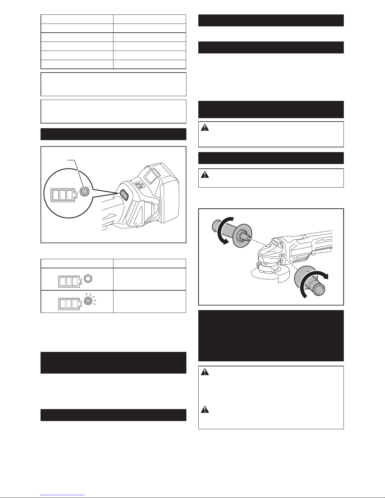
2
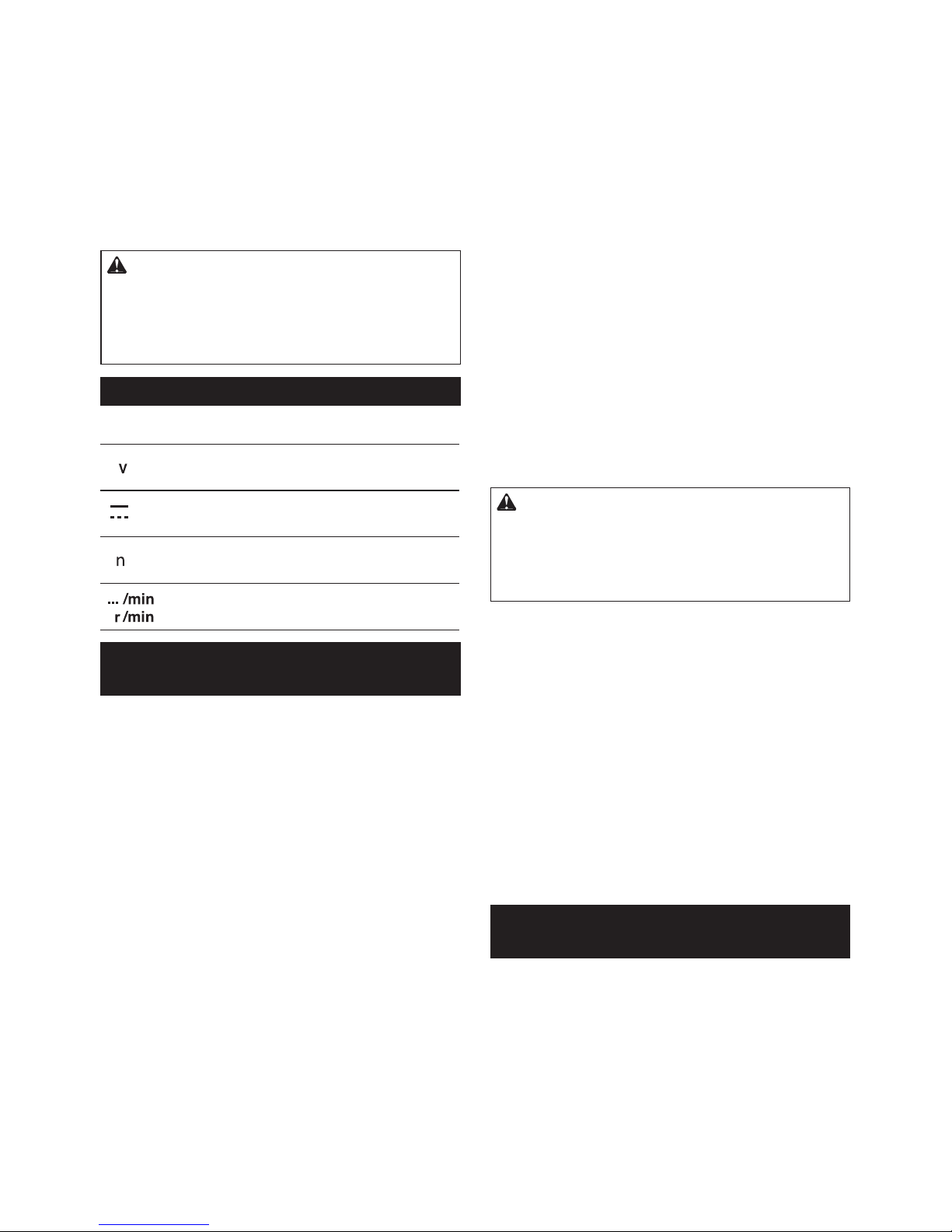
1
3
► 1. Red indicator 2. Button 3. Battery cartridge
To remove the battery cartridge, slide it from the tool
while sliding the button on the front of the cartridge.
To install the battery cartridge, align the tongue on the
battery cartridge with the groove in the housing and slip
it into place. Insert it all the way until it locks in place
with a little click. If you can see the red indicator on the
upper side of the button, it is not locked completely.
CAUTION: Always install the battery cartridge
fully until the red indicator cannot be seen. If not,
it may accidentally fall out of the tool, causing injury to
you or someone around you.
CAUTION: Do not install the battery cartridge
forcibly. If the cartridge does not slide in easily, it is
not being inserted correctly.
8 ENGLISH
Indicating the remaining battery
capacity
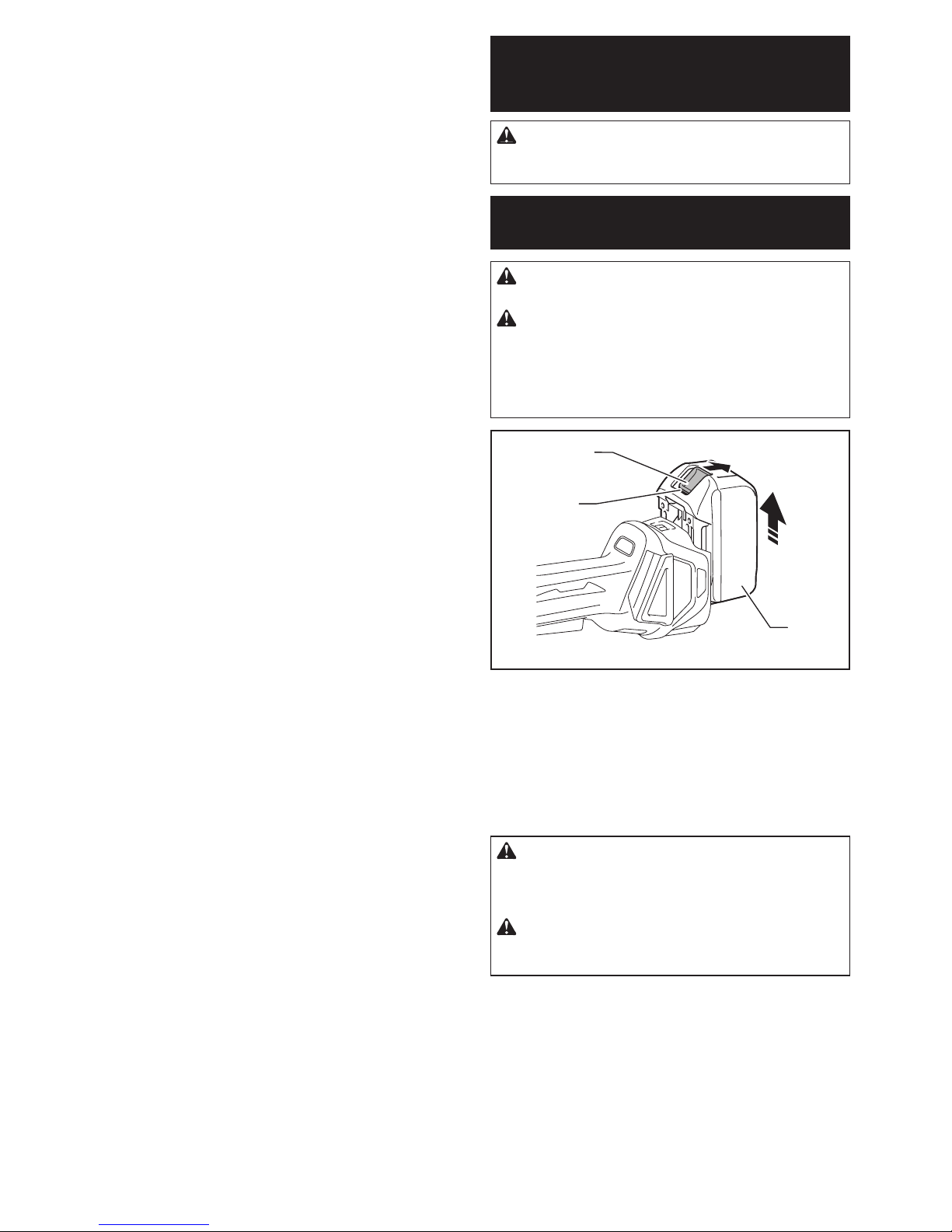
Only for battery cartridges with the indicator
1
2
► 1. Indicator lamps 2. Check button
Press the check button on the battery cartridge to indicate the remaining battery capacity. The indicator lamps
light up for a few seconds.
Indicator lamps Remaining
capacity
Lighted Off Blinking
75% to 100%
50% to 75%
25% to 50%
0% to 25%
Charge the
battery.
The battery
may have
malfunctioned.
NOTE: Depending on the conditions of use and the
ambient temperature, the indication may differ slightly
from the actual capacity.
Indicating the remaining battery
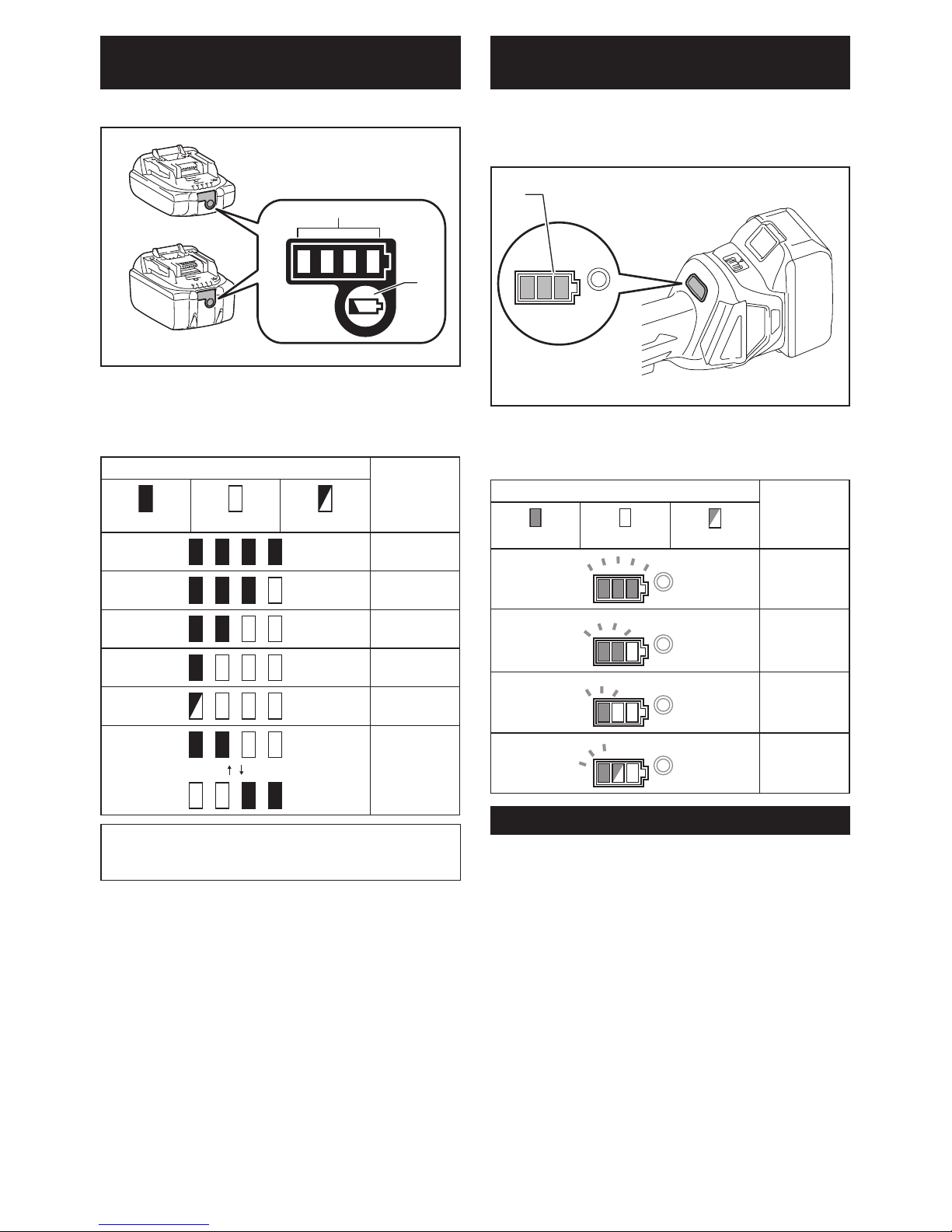
capacity
Country specic
When you turn the tool on, the battery indicator shows
the remaining battery capacity.
1
► 1. Battery indicator
The remaining battery capacity is shown as the follow-
ing table.
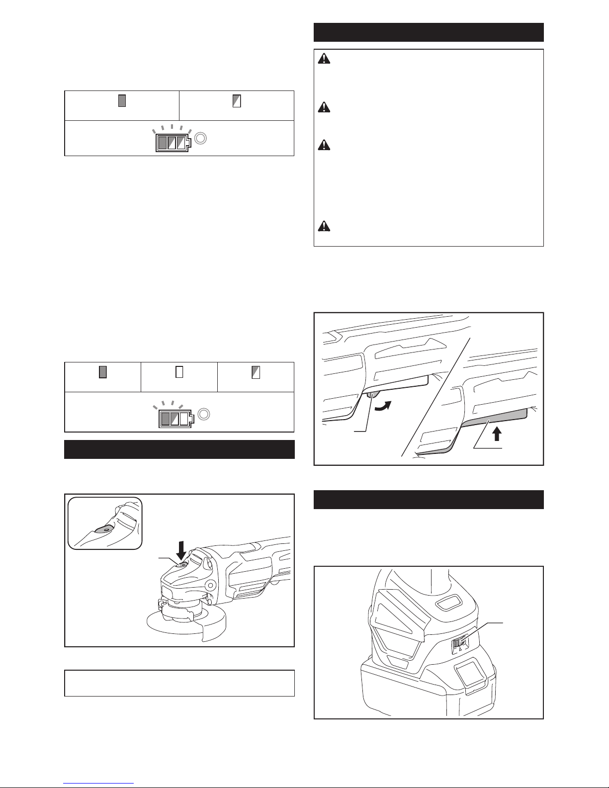
Battery indicator status Remaining
battery
capacity
On
Off
Blinking
50% to 100%
20% to 50%
0% to 20%
Charge the
battery
Tool / battery protection system
The tool is equipped with a tool/battery protection system. This system automatically cuts off power to the
motor to extend tool and battery life. The tool will automatically stop during operation if the tool or battery is
placed under one of the following conditions:
Overload protection
When the tool is operated in a manner that causes it to
draw an abnormally high current, the tool automatically
stops without any indication. In this situation, turn the
tool off and stop the application that caused the tool to
become overloaded. Then turn the tool on to restart.
9 ENGLISH
Overheat protection
When the tool is overheated, the tool stops automati-
cally and the battery indicator shows following state. In
this situation, let the tool cool before turning the tool on
again.
On
Blinking
If the tool does not start, the battery may be overheated.
In this situation, let the battery cool before starting the
tool again.
Overdischarge protection
When the battery capacity is not enough, the tool stops
automatically. In this case, remove the battery from the
tool and charge the battery.
Releasing protection lock
When the protection system works repeatedly, the tool
is locked and the battery indicator shows the following
state.
In this situation, the tool does not start even if turning
the tool off and on. To release the protection lock,
remove the battery, set it to the battery charger and wait
until the charging nishes.
On
Off
Blinking
Shaft lock
Press the shaft lock to prevent spindle rotation when
installing or removing accessories.
1
► 1. Shaft lock
NOTICE: Never actuate the shaft lock when the
spindle is moving. The tool may be damaged.
Switch action
CAUTION: Before installing the battery car-
tridge into the tool, always check to see that the
switch lever actuates properly and returns to the
"OFF" position when released.
CAUTION: Do not pull the switch lever hard
without pulling the lock-off lever. This can cause
switch breakage.
CAUTION: For your safety, this tool is
equipped with lock-off lever which prevents the
tool from unintended starting. NEVER use the tool
if it runs when you simply pull the switch trigger
without pulling the lock-off lever. Return the tool
to our authorized service center for proper repairs
BEFORE further usage.
CAUTION: NEVER tape down or defeat pur-
pose and function of lock-off lever.
To prevent the switch lever from being accidentally
pulled, a lock-off lever is provided.
To start the tool, pull the lock-off lever toward the operator and then pull the switch lever.
To stop the tool, release the switch lever.
2
1
► 1. Lock-off lever 2. Switch lever
Speed adjusting dial
The rotation speed of the tool can be changed by turning the speed adjusting dial. The table below shows
the number on the dial and the corresponding rotation
speed.
1
► 1. Speed adjusting dial
10 ENGLISH
Number Speed
1 3,000/min
2 4,500/min
3 6,000/min
4 7,500/min
5 8,500/min
NOTICE: If the tool is operated continuously at
low speed for a long time, the motor will get overloaded, resulting in tool malfunction.
NOTICE: When changing the speed dial from "5"
to "1", turn the dial counterclockwise. Do not turn
the dial clockwise forcibly.
Automatic speed change function
1
► 1. Mode indicator
Mode indicator status Operation mode
High speed mode
High torque mode
This tool has "high speed mode" and "high torque
mode". It automatically changes operation mode
depending on the work load. When mode indicator
lights up during operation, the tool is in high torque
mode.
Accidental re-start preventive
function
Even if installing the battery cartridge while pulling the
switch lever, the tool does not start.
To start the tool, rst release the switch lever. Then pull
the lock-off lever, and pull the switch lever.
Electronic torque control function
The tool electronically detects situations where the wheel
or accessory may be at risk to be bound. In the situation,
the tool is automatically shut off to prevent further rotation
of the spindle (it does not prevent kickback).
To restart the tool, switch off the tool rst, remove the
cause of sudden drop in the rotation speed, and then
turn the tool on.
Soft start feature
Soft start feature reduces starting reaction.
Electric brake
Electric brake is activated after the tool is switched off.
The brake does not work when the power supply is shut
down, such as the battery is removed accidentally, with
the switch still on.
ASSEMBLY
CAUTION: Always be sure that the tool is
switched off and the battery cartridge is removed
before adjusting or checking function on the tool.
Installing side grip (handle)
CAUTION: Always be sure that the side grip is
installed securely before operation.
Screw the side grip securely on the position of the tool
as shown in the gure.
Installing or removing wheel guard
(For depressed center wheel, multi-
disc, ex wheel, wire wheel brush
/ abrasive cut-off wheel, diamond
wheel)
WARNING: When using a depressed center
wheel, multi-disc, ex wheel or wire wheel brush,
the wheel guard must be tted on the tool so that
the closed side of the guard always points toward
the operator.
WARNING: When using an abrasive cut-off
/ diamond wheel, be sure to use only the special
wheel guard designed for use with cut-off wheels.
11 ENGLISH
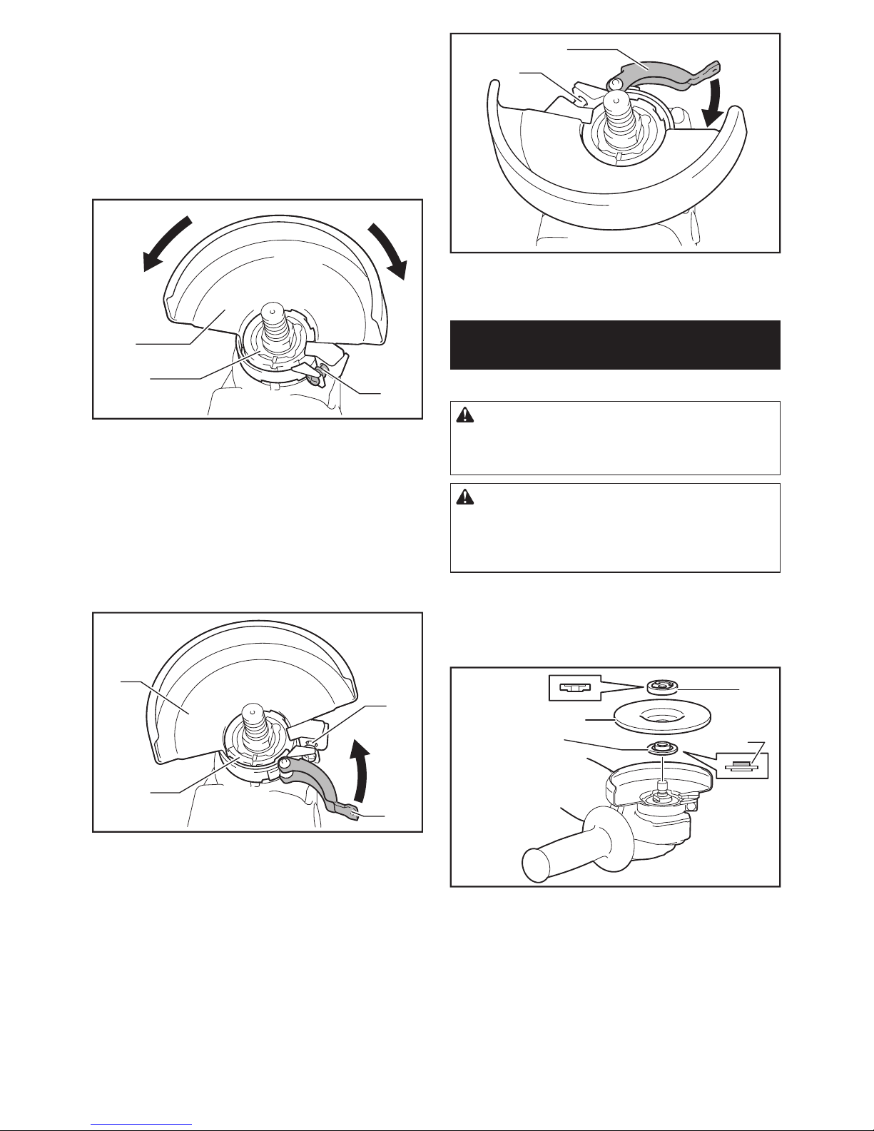
For tool with locking screw type
wheel guard
Mount the wheel guard with the protrusions on the
wheel guard band aligned with the notches on the bear-
ing box. Then rotate the wheel guard to such an angle
that it can protect the operator according to work. Be
sure to tighten the screw securely.
To remove wheel guard, follow the installation proce-
dure in reverse.
1
2
3
► 1. Wheel guard 2. Bearing box 3. Screw
For tool with clamp lever type wheel
guard
Loosen the screw, and then pull the lever in the direction of the arrow. Mount the wheel guard with the protrusions on the wheel guard band aligned with the notches
on the bearing box. Then rotate the wheel guard to such
an angle that it can protect the operator according to
work.
1
2
3
4
► 1. Wheel guard 2. Bearing box 3. Screw 4. Lever
Pull the lever in direction of the arrow. Then tighten the
wheel guard with fastening the screw. Be sure to tighten
the screw securely. The setting angle of the wheel
guard can be adjusted with the lever.
1
2
► 1. Screw 2. Lever
To remove wheel guard, follow the installation proce-
dure in reverse.
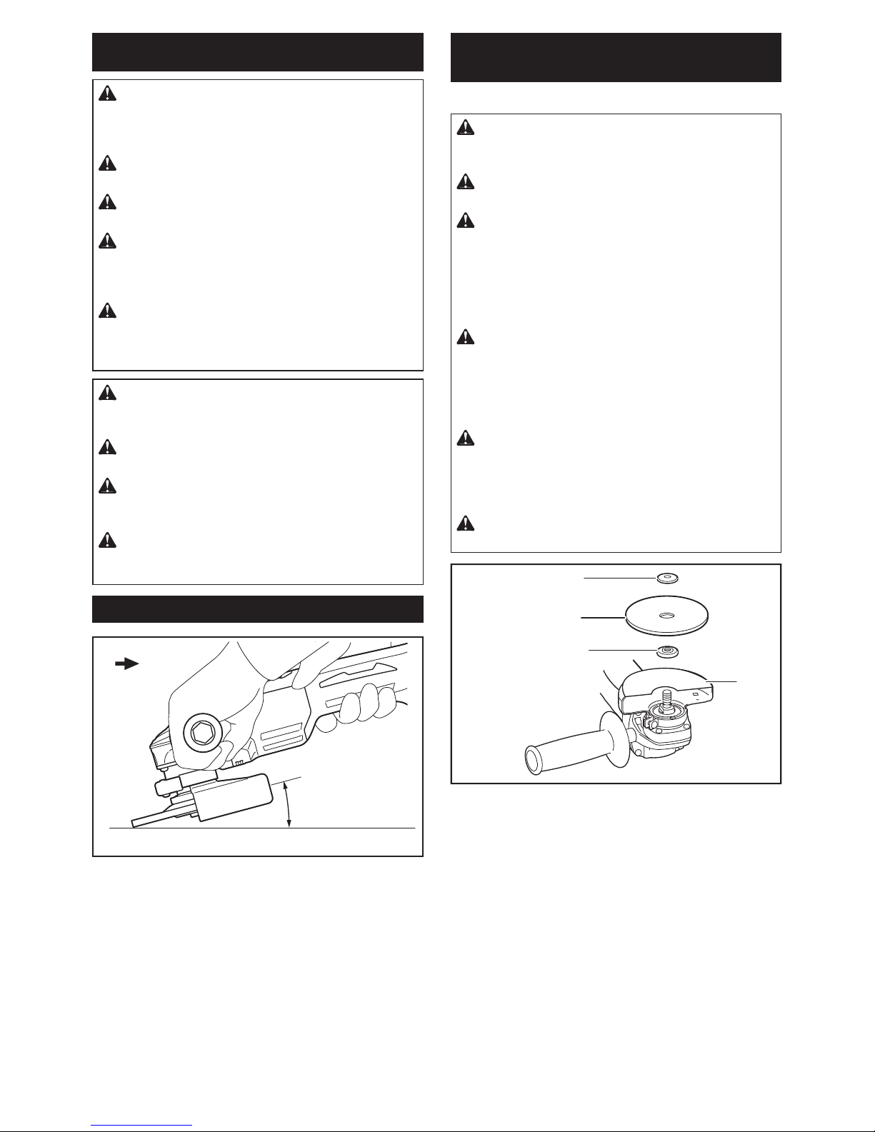
Installing or removing depressed
center wheel or multi-disc
Optional accessory
WARNING: When using a depressed center
wheel or multi-disc, the wheel guard must be
tted on the tool so that the closed side of the
guard always points toward the operator.
CAUTION: Make sure that the mounting part
of the inner ange ts into the inner diameter of
the depressed center wheel / multi-disc perfectly.
Mounting the inner ange on the wrong side may
result in the dangerous vibration.
Mount the inner ange onto the spindle.
Make sure to t the dented part of the inner ange onto
the straight part at the bottom of the spindle.
Fit the depressed center wheel / multi-disc on the inner
ange and screw the lock nut onto the spindle.
1
2
4
3
► 1. Lock nut 2. Depressed center wheel 3. Inner
ange 4. Mounting part
To tighten the lock nut, press the shaft lock rmly so
that the spindle cannot revolve, then use the lock nut
wrench and securely tighten clockwise.
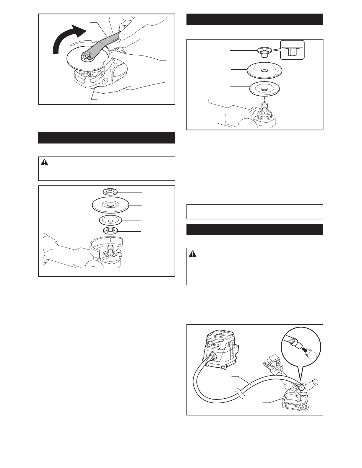
12 ENGLISH
1
2
► 1. Lock nut wrench 2. Shaft lock
To remove the wheel, follow the installation procedure
in reverse.
Installing or removing ex wheel
Optional accessory
WARNING: Always use supplied guard when
ex wheel is on tool. Wheel can shatter during use
and guard helps to reduce chances of personal injury.
1
2
3
4
► 1. Lock nut 2. Flex wheel 3. Back up pad 4. Inner
ange
Follow instructions for depressed center wheel but also
use back up pad over wheel. See order of assembly on
accessories page in this manual.
Installing or removing abrasive disc
Optional accessory
1
2
3
► 1. Sanding lock nut 2. Abrasive disc 3. Rubber pad
1. Mount the rubber pad onto the spindle.
2. Fit the disc on the rubber pad and screw the sand-
ing lock nut onto the spindle.
3. Hold the spindle with the shaft lock, and securely
tighten the sanding lock nut clockwise with the lock nut
wrench.
To remove the disc, follow the installation procedure in
reverse.
NOTE: Use sander accessories specied in this manual. These must be purchased separately.
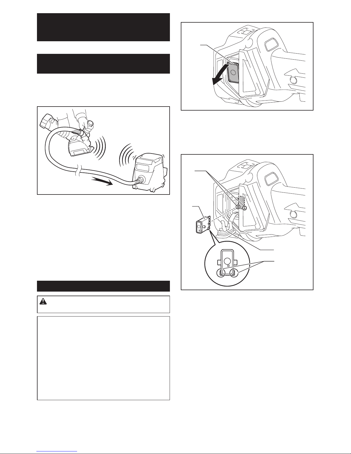
Connecting a vacuum cleaner
Optional accessory
WARNING: Never vacuum metal particles
created by grinding/cutting/sanding operation.
Metal particles created by such operation are so hot
that they ignite dust and the lter inside the vacuum
cleaner.
To avoid dusty environment caused by masonry cutting, use a dust collecting wheel guard and a vacuum
cleaner.
Refer to the instruction manual attached to the dust
collecting wheel guard for assembling and using it.
2
1
► 1. Dust collecting wheel guard 2. Hose of the vac-
uum cleaner
13 ENGLISH
OPERATION
WARNING: It should never be necessary to
force the tool. The weight of the tool applies ade-
quate pressure. Forcing and excessive pressure
could cause dangerous wheel breakage.
WARNING: ALWAYS replace wheel if tool is
dropped while grinding.
WARNING: NEVER bang or hit grinding disc
or wheel onto work.
WARNING: Avoid bouncing and snagging
the wheel, especially when working corners,
sharp edges etc. This can cause loss of control and
kickback.
WARNING: NEVER use tool with wood cutting
blades and other saw blades. Such blades when
used on a grinder frequently kick and cause loss of
control leading to personal injury.
CAUTION: Never switch on the tool when it
is in contact with the workpiece, it may cause an
injury to operator.
CAUTION: Always wear safety goggles or a
face shield during operation.
CAUTION: After operation, always switch off
the tool and wait until the wheel has come to a
complete stop before putting the tool down.
CAUTION: ALWAYS hold the tool rmly with
one hand on housing and the other on the side
grip (handle).
Grinding and sanding operation
15°
Turn the tool on and then apply the wheel or disc to the
workpiece.
In general, keep the edge of the wheel or disc at an
angle of about 15° to the workpiece surface.
During the break-in period with a new wheel, do not
work the grinder in forward direction or it may cut into
the workpiece. Once the edge of the wheel has been
rounded off by use, the wheel may be worked in both
forward and backward direction.
Operation with abrasive cut-off /
diamond wheel
Optional accessory
WARNING: When using an abrasive cut-off
/ diamond wheel, be sure to use only the special
wheel guard designed for use with cut-off wheels.
WARNING: NEVER use cut-off wheel for side
grinding.
WARNING: Do not "jam" the wheel or apply
excessive pressure. Do not attempt to make an
excessive depth of cut. Overstressing the wheel
increases the loading and susceptibility to twisting
or binding of the wheel in the cut and the possibility
of kickback, wheel breakage and overheating of the
motor may occur.
WARNING: Do not start the cutting operation
in the workpiece. Let the wheel reach full speed
and carefully enter into the cut moving the tool
forward over the workpiece surface. The wheel
may bind, walk up or kickback if the power tool is
started in the workpiece.
WARNING: During cutting operations, never
change the angle of the wheel. Placing side pres-
sure on the cut-off wheel (as in grinding) will cause
the wheel to crack and break, causing serious per-
sonal injury.
WARNING: A diamond wheel shall be oper-
ated perpendicular to the material being cut.
1
2
3
4
► 1. Lock nut 2. Abrasive cut-off wheel / diamond
wheel 3. Inner ange 4. Wheel guard for abrasive
cut-off wheel / diamond wheel
As for the installation, follow the instructions for
depressed center wheel.
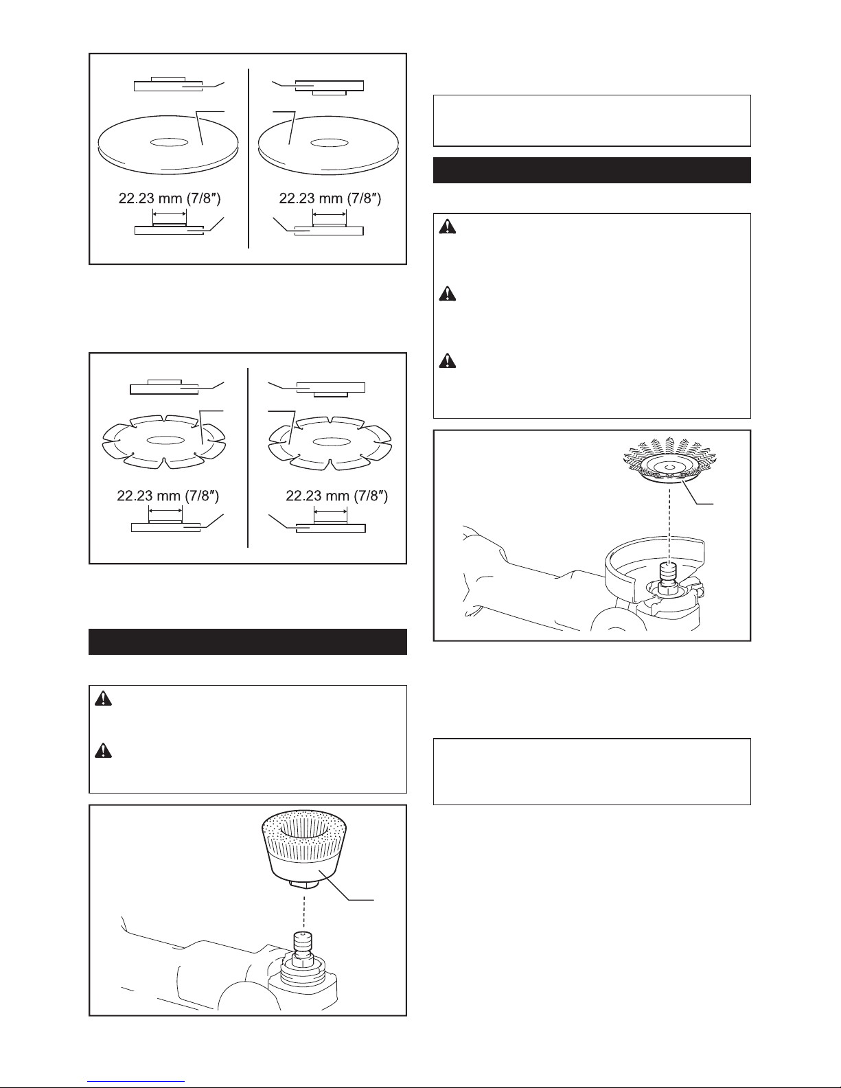
The direction for mounting the lock nut and the
inner ange varies by wheel type and thickness.
Refer to the following gures.
14 ENGLISH
When installing the abrasive cut-off wheel:
11
44
23
► 1. Lock nut 2. Abrasive cut-off wheel (Thinner than
4mm (5/32")) 3. Abrasive cut-off wheel (4mm (5/32")
or thicker) 4. Inner ange
When installing the diamond wheel:
11
44
23
► 1. Lock nut 2. Diamond wheel (Thinner than 4mm
(5/32″)) 3. Diamond wheel (4mm (5/32″) or thicker)
4. Inner ange
Operation with wire cup brush
Optional accessory
CAUTION: Check operation of brush by run-
ning tool with no load, insuring that no one is in
front of or in line with brush.
CAUTION:
Do not use brush that is damaged, or
which is out of balance. Use of damaged brush could increase
potential for injury from contact with broken brush wires.
1
► 1. Wire cup brush
Remove the battery cartridge from the tool and place it
upside down allowing easy access to spindle.
Remove any accessories on spindle. Thread wire cup
brush onto spindle and tighten with supplied wrench.
NOTICE: Avoid applying too much pressure
which causes over bending of wires when using
brush. It may lead to premature breakage.
Operation with wire wheel brush
Optional accessory
CAUTION: Check operation of wire wheel
brush by running tool with no load, insuring that
no one is in front of or in line with the wire wheel
brush.
CAUTION: Do not use wire wheel brush that
is damaged, or which is out of balance. Use of
damaged wire wheel brush could increase potential
for injury from contact with broken wires.
CAUTION: ALWAYS use guard with wire
wheel brushes, assuring diameter of wheel ts
inside guard. Wheel can shatter during use and
guard helps to reduce chances of personal injury.
1
► 1. Wire wheel brush
Remove the battery cartridge from the tool and place it
upside down allowing easy access to spindle.
Remove any accessories on spindle. Thread wire wheel
brush onto spindle and tighten with the wrenches.
NOTICE: Avoid applying too much pressure
which causes over bending of wires when
using wire wheel brush. It may lead to premature
breakage.
15 ENGLISH
WIRELESS ACTIVATION
FUNCTION
For XAG21 only
What you can do with the wireless
activation function
The wireless activation function enables clean and comfortable operation. By connecting a supported vacuum
cleaner to the tool, you can run the vacuum cleaner
automatically along with the switch operation of the tool.
To use the wireless activation function, prepare follow-
ing items:
• A wireless unit
• A vacuum cleaner which supports the wireless
activation function
The overview of the wireless activation function
setting is as follows. Refer to each section for detail
procedures.
1. Installing the wireless unit
2. Tool registration for the vacuum cleaner
3. Starting the wireless activation function
Installing the wireless unit
CAUTION: Place the tool on a at and stable
surface when installing the wireless unit.
NOTICE: Clean the dust and dirt on the tool
before installing the wireless unit. Dust or dirt
may cause malfunction if it comes into the slot of the
wireless unit.
NOTICE: To prevent the malfunction caused by
static, touch a static discharging material, such
as a metal part of the tool, before picking up the
wireless unit.
NOTICE: When installing the wireless unit,
always be sure that the wireless unit is inserted
in the correct direction and the lid is completely
closed.
1. Open the lid on the tool as shown in the gure.
1
► 1. Lid
2. Insert the wireless unit to the slot and then close
the lid.
When inserting the wireless unit, align the projections
with the recessed portions on the slot.
2
1
3
4
► 1. Wireless unit 2. Projection 3. Lid 4. Recessed
portion
When removing the wireless unit, open the lid slowly.
The hooks on the back of the lid will lift the wireless unit
as you pull up the lid.
 Loading...