

Makita UH6300, UH4500 Technical Information
T
ECHNICAL INFORMATION
New Tool
Models No.
Description
UH 6300
MAKITA 45 0m m&630m m He dge Tr im mer
CONCEPTION AND MAIN APPLICATIONS
This is a product newly developed on the demands fr om the
European countries, and is to be launched in the gardening tools
market. Security and easiness of operation are pursued. It has
more power than other manufacturers' products for better
effectiveness in work. And two other models of different
effective blade length have been developed to meet the demands
of the different users.
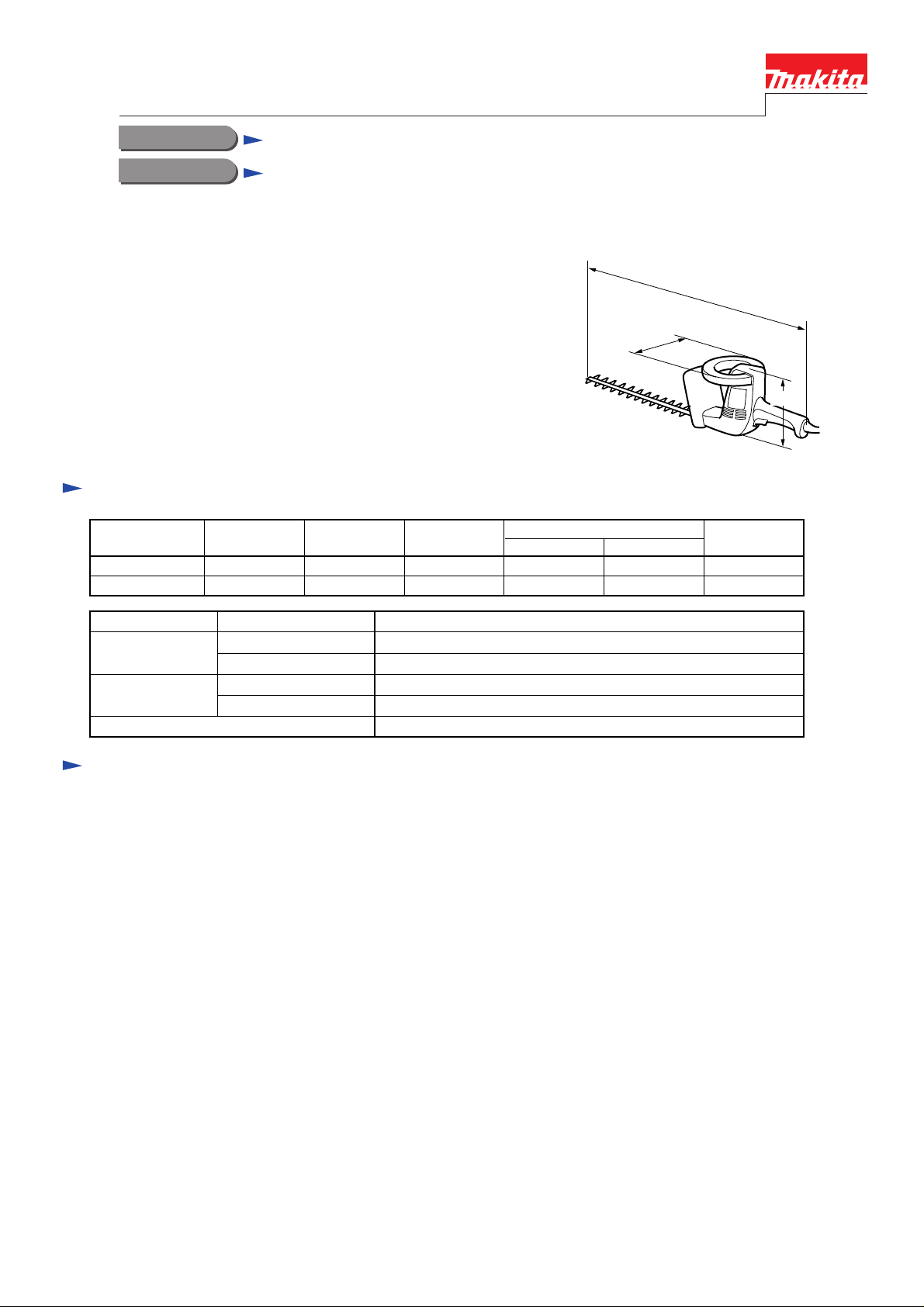
Specifications
Model
UH4500
UH6300
Voltage (V)
100 5.3 50/60 500 250 360
100 5.3 50/60 500 250 360
Current (A) Cycle (Hz)
Continuous rating
Input(W)
Output(W)
759(UH4500)
939(UH6300)
174
176
Max.
Output(W)
No Load Speed
Effe ct i v e b l a de
Leng t h (mm)
Net Weight (kg)
Power supply cord (m)
No. of striking(/min.)
UH4500
UH6300
UH4500
UH6300
Optional accessories
Shear blade assembly
1,700/min.
450 mm
630 mm
3.1 kg
3.4 kg
2.5 m
The standard equipment for the tools shown may differ form country to country
Repair
Assembly/Disassembly
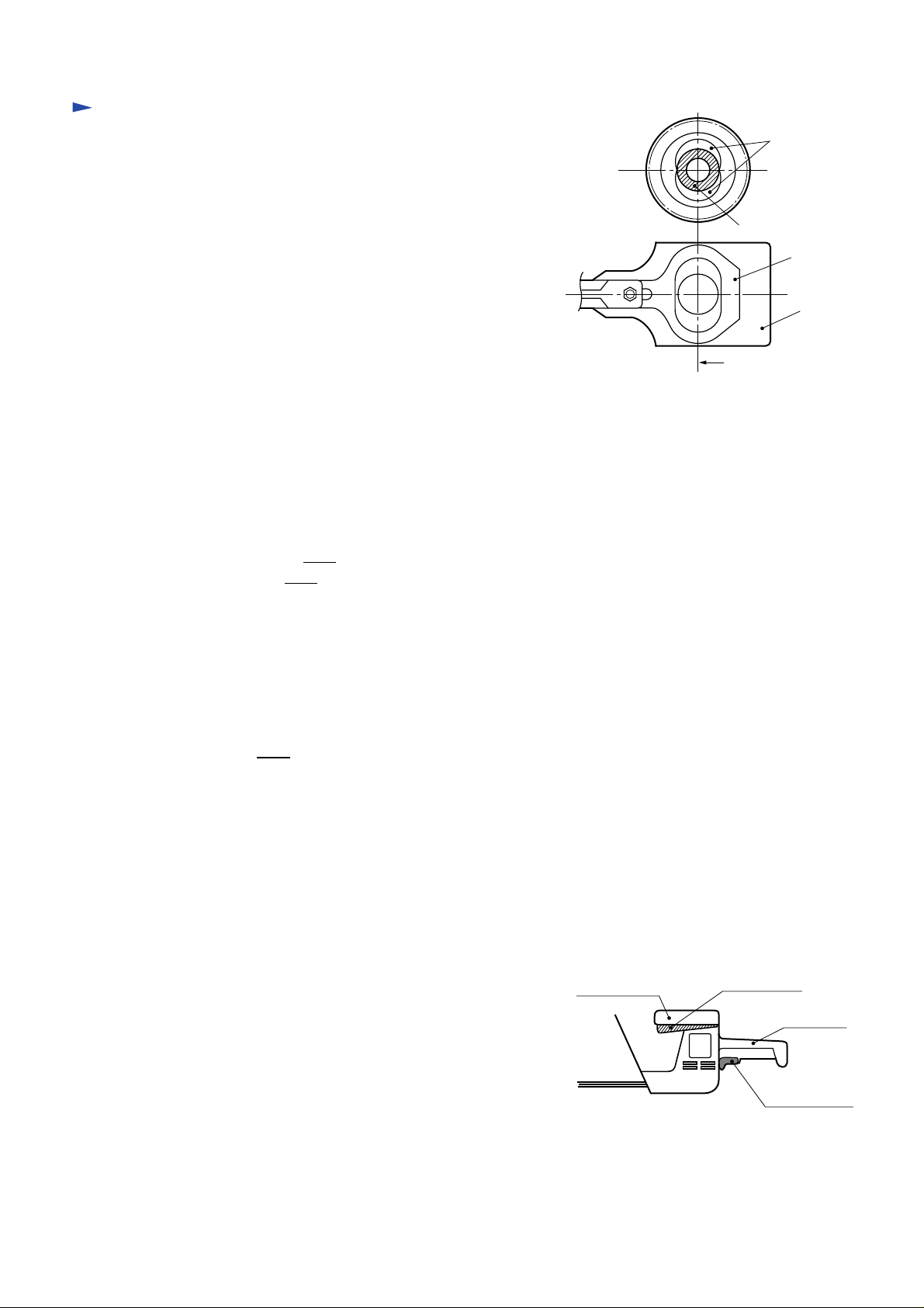
1) Fitting of the gear shaft complete to shear blade assembly
Center the long hole of the shear blades A,B with the
round hole of the guide plate. Center the two crank
plates with that center as shown in the right sketch. Set
ball bearing 6002 and shear blades A,B face to face.
After assembling, check if the shear blades A,B move
smoothly by turning the gear by hand.
Shear blades
The blade A and the blade B have the same weight so that the vibration of the repeated movement can be offset.
Therefore, when there is an inequality of weight due to grinding or breakage of a blade, vibration of the body
becomes big in proportion to the imbalance. In such a case the shear blade assembly should be replaced.
Different parts between #UH4500 and # UH 6300(electrical parts excluded)
(1) Main Body
Substitute parts
Shear blade assembly 1 piece
identification plate 1 piece
Additional parts
none
Excluded parts
none
Crank Plates(2 sheets)
Ball bearing 6002
Shear blades A,B
Center of the long
hole and the crank plates
Guide plate
(2) Norm al Accessories
Substitute piece
Card board case 1
Additional piece
none
Excluded piece
none
Operation Mode
(1) S witch o per ati o n
Two different switches should be activated to start
operation because this tool has adopted double hand
switch mechanism. For activation, the main switch on the
grip should be pulled by one hand and the loop-shaped
sub switch on the handle held by the other. If either of the
two switches is released, the machine will stop.
Handle
Sub switch
Grip
Main switch
 Loading...