

Page 1
PRODUCT
CONCEPT AND MAIN APPLICATIONS
P 1/ 13
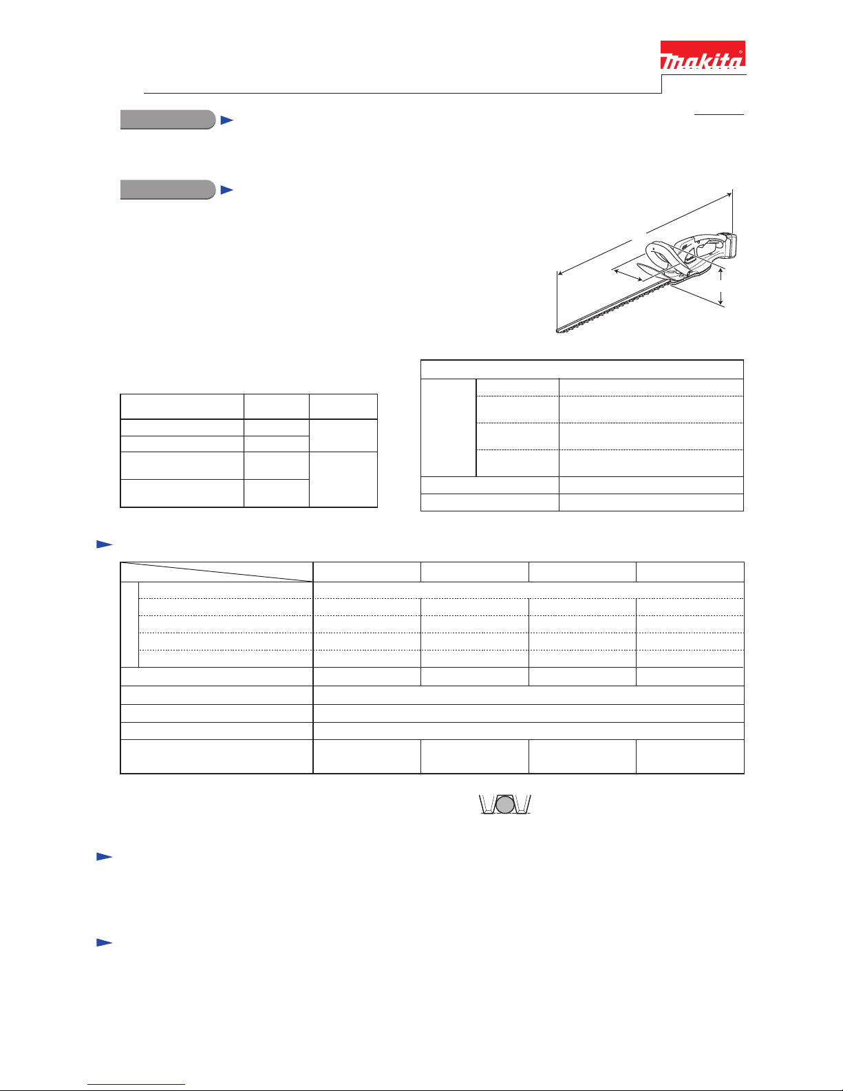
Specification
Standard equipment
Optional accessories
Note: The standard equipment for the tool shown above may vary by country.
Model No.
Description
UH520D
UH422D/ UH482D/ UH522D
BUH481/ BUH521
BUH483/ BUH523
Cordless Hedge Trimmer 520mm (20-1/2")
Cordless Hedge Trimmers 420mm/ 480mm/ 520mm
(16-1/2"/ 18-7/8"/ 20-1/2")
Cordless Hedge Trimmers 480mm/ 520mm (18-7/8"/ 20-1/2")
Cordless Hedge Trimmers 480mm/ 520mm (18-7/8"/ 20-1/2")
Dimensions: mm (")
Width (W)
Height (H)
*2 with 3.0Ah Li-ion battery *3 with 1.3Ah Li-ion battery
Length (L)
888 (35)/ 938 (37)*1
873 (34-3/8)/ 923 (36-1/4)*3
923 (36-1/4)
829 (32-5/8)/ 879 (34-1/2)/ 929 (36-1/2)
BUH483/ 523
881 (34-3/4)/ 931 (36-3/4)*2
869 (34-1/4)/ 919 (36-1/4)*3
BUH481/ 521
UH520D
UH422D/ 482D/
522D
195 (7-5/8)
193 (7-5/8)
Battery
Charging time (approx.): min.
Weight according to
EPTA-Procedure 01/2003*
5: kg (lbs)
Capacity: Ah
Cell
Voltage: V
14.414.4 18
No load speed: min
ˉ¹=spm*3
420 (16-1/2)/ 480 (18-7/8)/ 520 (20-1/2)
--- / --- / UH520D --- / BUH481/ 521 --- / BUH483/ 523
Blade length: mm (")
--- / --- / 3.0
(--- / --- / 6.7)
--- / 3.0/ 3.0 (--- / 6.5/ 6.7),
--- / 3.1/ 3.2 (--- / 6.9/ 7.1)
3.0/ 3.0/ 3.1
(6.6/ 6.7/ 6.8)
--- / 3.0/ 3.1 (--- / 6.7/ 6.8),
--- / 3.2/ 3.3 (--- / 7.1/ 7.3)
1.3, 3.01.1 1.3, 3.0
Energy capacity: Wh 19, 4416 24, 54
Li-ion
190190 210210
15, 22 with DC18RC60 with DC18WA
18
UH422D/ 482D/ 522D
1.1
20
60 with DC18WA 15, 22 with DC18RC
1,350
Max output (W)
Blade cover ............................................. 1
Battery cover ........................................... 1 (same quantity as that of spare battery)
Battery BL1815 (for BUH483/ 523)
Battery BL1830 (for BUH483/ 523)
Charger DC18WA (for UH422D/ 482D/ 520D/ 522D)
Fast charger DC18RC (for BUH481/ 483/ 521/ 523)
Charger DC18SD (for BUH481/ 483/ 521/ 523)
Charger DC24SC (for BUH481/ 483/ 521/ 523)
Automotive charger DC18SE (for BUH481/ 483/ 521/ 523)
The subject models are 14.4V/18V cordless hedge trimmers.
Their main features are:
• Anti-vibration structure
• User-replaceable blade
These products are compatible with the batteries
and the chargers in the list below.
BUH483/ 523
UH422D/ 482D/ 522D BL1811G
UH520D BL1411G
DC18WA
BUH481/ 521
BL1415
BL1430
DC18RC,
DC18SD,
DC24SC,
DC18SE
Model No.
Compatible
charger
BL1815
BL1830
Compatible
battery
Model
Specification
*3: spm= strokes per minute
*4: Indicates maximum diameter of the branch that can be received
between adjacent two blade teeth. (See the figure on right.)
*5: with battery, shear blade assembly
Shear blade complete set
Blade cover
Chip receiver assembly set
Battery BL1411G (for UH520D)
Battery BL1811G (for UH422D/ 482D/ 522D)
Battery BL1415 (for BUH481/ 521)
Battery BL1430 (for BUH481/ 521)
Max. cutting diameter*
4: mm (") ø15 (9/16)
T
ECHNICAL INFORMATION
L
H
W
Page 2
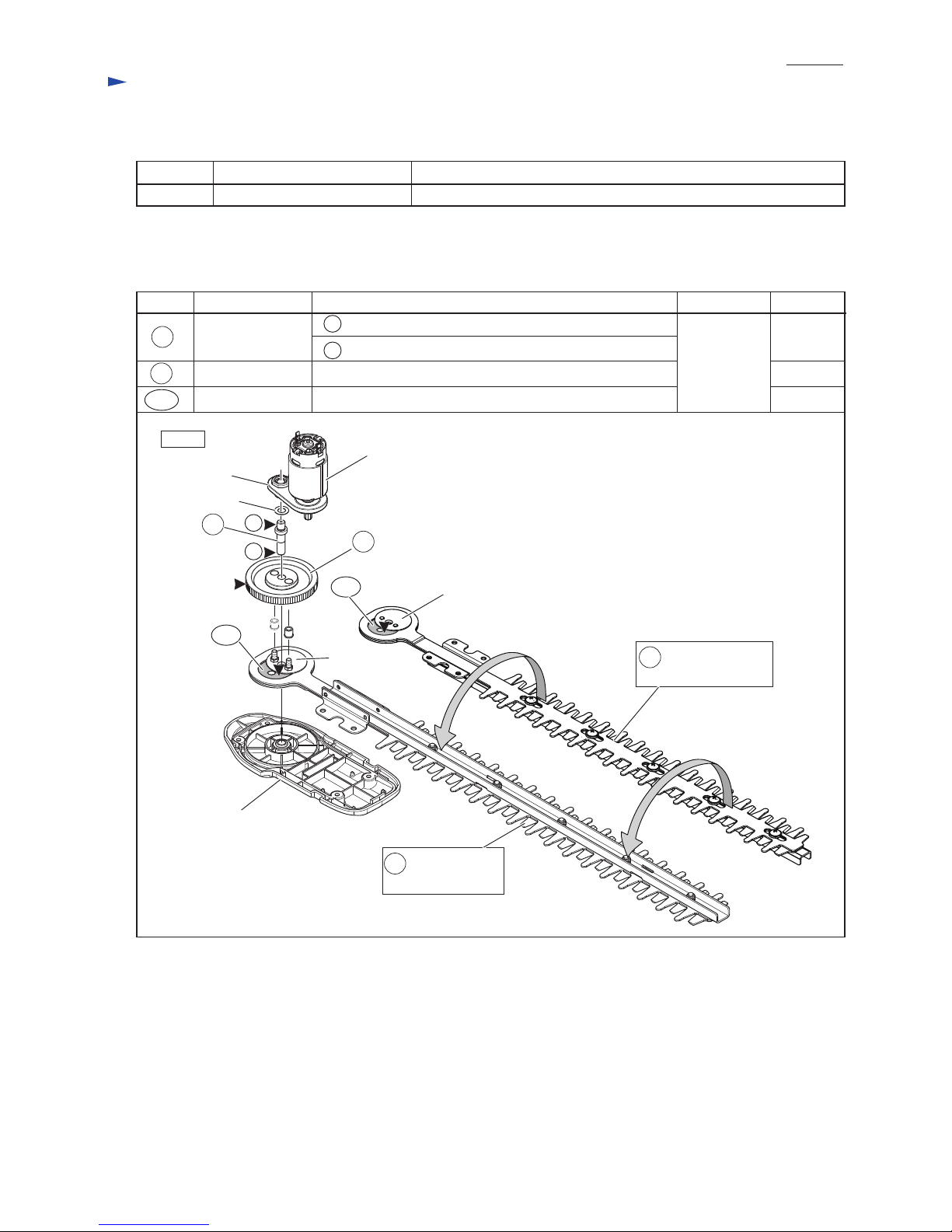
Apply the following grease to the portions designated with the black triangle to protect parts and product from unusual
abrasion.
[1] NECESSARY REPAIRING TOOLS
Code No. Description Use for
1R035 Bearing Setting Plate Supporting Spur gear 93, when removing Spindle with Arbor press
[2] LUBRICATION
Fig. 1
Item No. Description
Grease
Makita
grease N
No.2
Amount
Portion to lubricate
27A
24
23
Flat washer 8
Bearing box
Crank plate B
Under cover
DC motor
a
b
27A
27 viewed from
Under cover side
Crank plate A
23 Spindle
The drum portion which is accepted by Bearing box
The drum portion which is accepted by Under cover
24 Spur gear 93 Teeth portion for smooth engaging with DC motor’s gear
27 viewed from
Front grip side
Both side where Crank plate A and Crank plate B contact 27A Spacer of Blade
a
a little
a little
b
3 g
CAUTION: Repair the machine in accordance with “Instruction manual” or “Safety instructions”.
Repair
P 2/ 13
Page 3
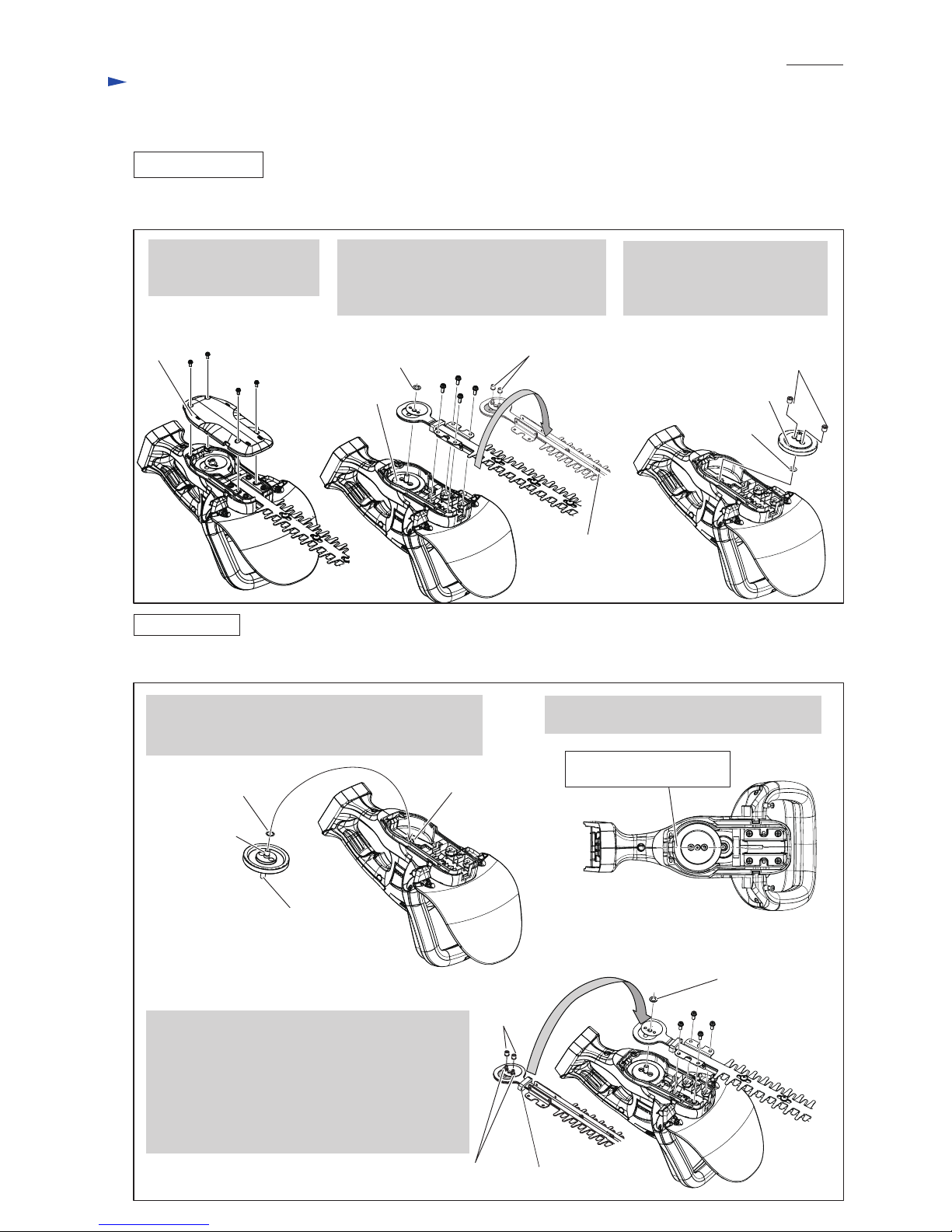
Fig. 2
Fig. 3
[3] DISASSEMBLY/ASSEMBLY
[3] -1. Shear blade complete
DISASSEMBLING
1. Remove Under cover by
unscrewing four M4x10
Pan head screws.
2. Remove Shear blade complete by
unscrewing four M5x14 Pan head screws.
And remove two Nylon sleeves from
Shear blade complete.
Shear blade viewed
from Front grip side
Nylon sleeve
(2 pcs.)
Nylon sleeve (2 pcs.)
Spur gear section
Spur gear section
ASSEMBLING
1. Pass Spindle through Flat washer 8 and then set them
in Bearing box complete so that the depressed side of
Spur gear 93 faces to Bearing box complete.
M5x14 Pan
head screw
(4 pcs.)
M5x14 Pan
head screw (4 pcs.)
M4x10 Pan head
screw (4 pcs.)
Under
cover
Disassemble Shear blade complete as drawn in Fig. 2.
Assemble Shear blade complete to the machine as drawn in Fig. 3.
Flat washer 8
3. If Nylon sleeves are left in
the holes of Spur gear section,
remove them after disassembly
of Super gear section.
Flat washer 8
Mating line of Housing L
and Housing R
2. Turn Spur gear 93 until its holes come on
the mating line of Housing set.
Flat washer 8
Spindle on the projected side
of Super gear 93 to Under cover
(Also refer to Fig. 12)
Spindle on
the depressed
side of Supper
gear 93 (Also
refer to Fig. 12)
Bearing box complete
Dust guard
Nylon sleeve
(2 pcs.)
Pins of Shear blade
complete (2 pcs.)
3. Set two Nylon sleeves to two pins of Shear blade
complete.
4. Set Dust guard to Shear blade complete.
Note: Dust gurad is not directional when assembled
with Shear blade complete.
5. Inserting the Nylon sleeves into the holes of
Spur gear 93, set Shear blade complete in place.
Do not forget to set Flat washer 8 to Spindle.
Repair
P 3/ 13
Page 4
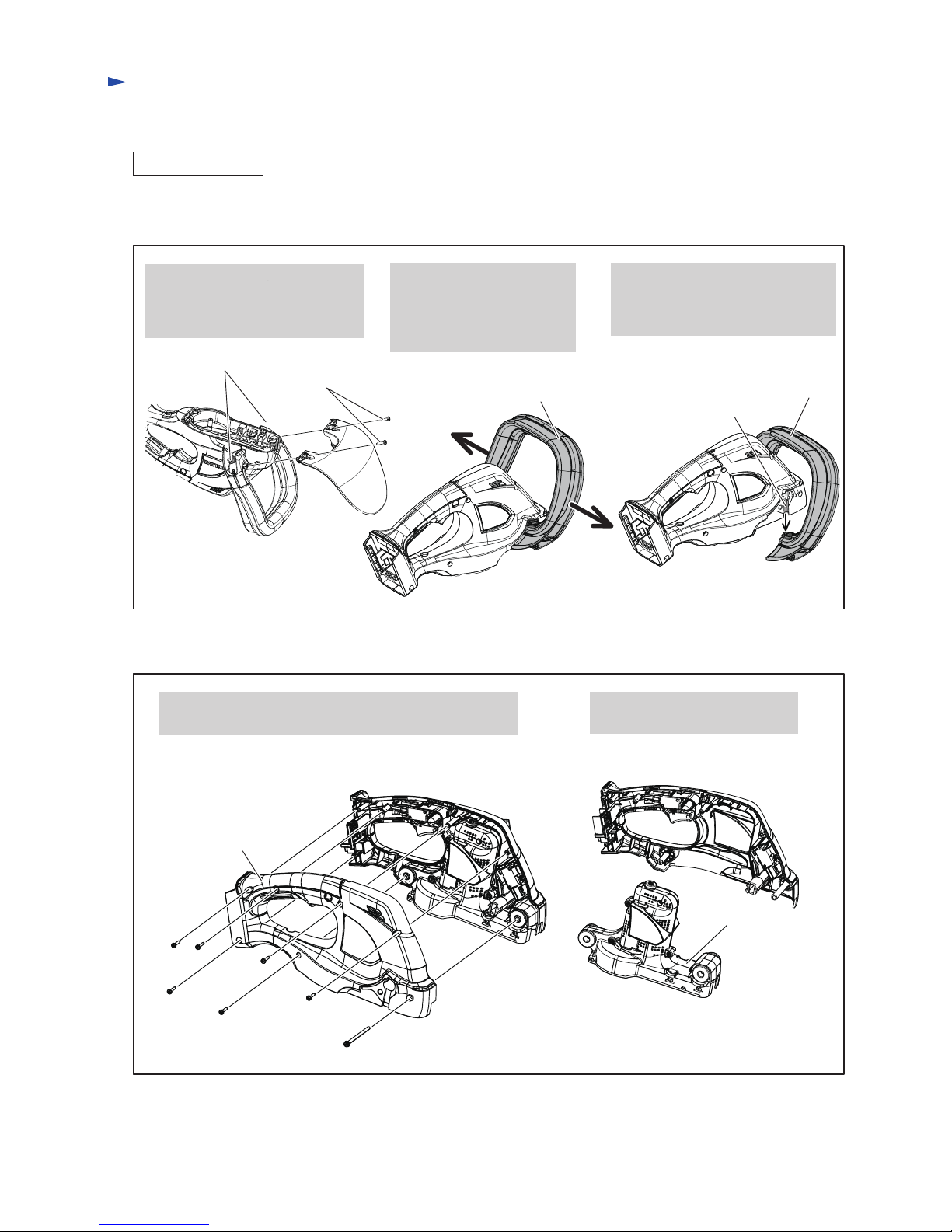
Fig. 4
Fig. 5
[3] DISASSEMBLY/ASSEMBLY
[3] -2. DC motor
DISASSEMBLING
(1) Disassemble Shear blade complete and Spur gear 93 as drawn in Fig. 2.
(2) Remove Protector and Front grip section as drawn in Fig. 4.
(3) Separate Housing R from Housing L. Then, remove Motor housing section from Housing L. See Fig. 5.
3x16 Tapping screw
(6 pcs.)
M4x65 Pan head screw
(1 pc.)
1. Remove Protector by unscrewing
two 4x18 Tapping screws.
And loosen two M5x25 Pan head
screws on the joints of Front grip.
1. Unscrewing six 3x16 Tapping screws and one M4x65
Pan head screw, separate Housing R from Housing L.
2.Separate Motor housing section
from Housing L.
2. Pulling Front grip toward
the direction designated
with arrow, remove it from
the holes on the both side
of Housing set.
3. Push Front grip along the grooves
on the both side of Housing set.
Front grip section is disassembled
from Housing set.
M5x25 Pan head
screw (2 pcs.)
Housing R
4x18 Tapping
screw (2 pcs.)
Motor housing section
groove
Front grip section Front grip section
Repair
P 4/ 13
Page 5
P 5/ 13
Fig. 6
Fig. 7
Repair
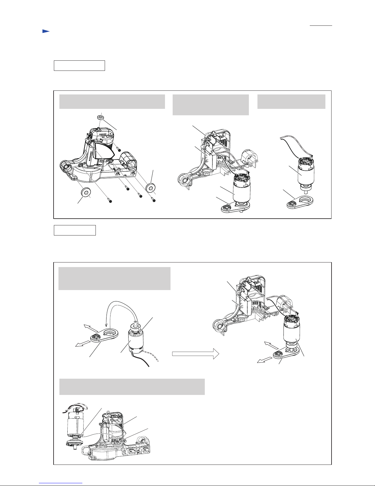
[3] DISASSEMBLY/ASSEMBLY
[3] -2. DC motor (cont.)
DISASSEMBLING
ASSEMBLING
(4) Disassemble DC Motor from Motor housing as drawn in Fig. 6.
(1) Assemble DC Motor in the reverse order of Disassembly. (Refer to Figs. 6, 5 and 4)
And also refer to Fig. 7.
3x16 Tapping
screw (5 pcs.)
Rubber ring 8
Rubber ring 8
Rubber ring 6
1. Remove one Rubber ring 6, two Rubber
rings 8 and five 3x16 Tapping screws.
2. Remove DC motor together
with Bearing retainer from
Motor housing L.
3. Separate DC Motor from
Bearing box complete.
DC Motor
Motor Housing L
Bearing box
complete
DC Motor
DC Motor
1. While facing M3x4 Hex socket head bolt to
Motor housing L side, mount DC Motor to
Bearing box complete.
M3x4
Hex socket
head bolt
M3x4 Hex socket head bolt
2. While fitting M3x4 Hex socket head bolt to Rib on Motor
housing L, assemble DC Motor to Motor housing (L).
Rib for M3x4 Hex
socket head bolt fitting
Bearing box
complete
Motor
housing L
side
Controller
side
Controller
Motor housing L
Bearing box
complete
Controller
Motor Housing L
Motor
housing L
side
Controller
side
DC motor
Bearing box
complete
Page 6
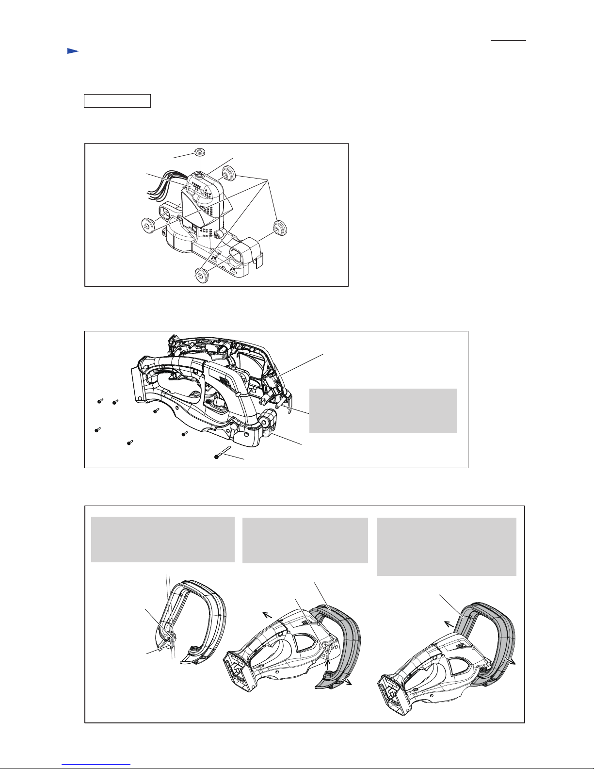
Note:
As this boss of Housing L is easy to be
deformed, tighten M4x65 Pan head
screw carefully.
Fig. 8
Fig. 9
Fig. 10
[3] DISASSEMBLY/ASSEMBLY
[3] -2. DC motor (cont.)
ASSEMBLING
(2) Fix Motor housing R and Motor housing L with Rubber rings as drawn in Fig. 8.
Motor housing L
Rubber ring 8 (4 pcs.)
Rubber ring 6
Motor housing R
(3) Setting Motor housing section to Housing L, set Housing R in place with six 3x16 Tapping screws
and one M4x65 Pan head screw as drawn in Fig. 9.
(4) Assemble Front grip section as drawn in Fig. 10.
Motor housing section
Housing L
Joint of
Switch lever B
1. Align the joints of Switch lever B
and Front grip in line for smooth
moving in the grooves on Housing
set.
2. Pulling Front grip section
to both side, fit the Joints of
Switch lever B and Front grip
to the grooves on Housing set.
3. Pulling Front grip section to both
side, fit Front grip section to the
holes on Housing set.
And tighten two M5x25 Pan head
screw on both side of Housing set.
Joint of
Front grip
groove
Front grip section
Front grip section
M4x65 Pan head screw
Repair
P 6/ 13
3x16 Tapping screw
(6 pcs.)
Page 7

Fig. 11
Fig. 12
[3] DISASSEMBLY/ASSEMBLY
[3] -3. Spur Gear 93
DISASSEMBLING
ASSEMBLING
(1) Assemble Spindle to Spur gear 93 as drawn in Fig. 12.
(2) Face its grooved side of Spur gear 93 to Bearing box complete and assemble Spur gear sesction to Bearing box
complete.
Note: Be sure to set two Flat washers 8 on both Spindle ends, two Nylon sleeves into holes of Shear blade complete
as drawn in Fig. 3.
1R035
Do not insert Spindle from the projected side of
Spur gear 93 because Crank pin can not be fit to
Spur gear 93 precisely.
Press-fit Spindle from the depressed side of
Spur gear 93 so that Shear blade complete is
assembled to Spur gear 93 precisely.
CORRECT WRONG
(1) Disassemble Shear blade complete, and then, remove Spur gear section as drawn in Fig. 2.
(2) Disassemble Spur gear 93 as drawn in Fig. 11.
Spindle
Spindle
Spur gear 93
1. Put Spur gear section on 1R035,
remove Spindle with Arbor press.
2. Spindle is removed
from Spur gear 93.
Crank pin
Spindle
Depressed side
of Spur gear 93
Projected side
of Spur gear 93
Spindle
Shear blade complete
Crank pin
Shear blade complete
Shear blade
complete
Repair
P 7/ 13
Page 8

Fig. 13
[3] DISASSEMBLY/ASSEMBLY
[3] -4. Front grip
DISASSEMBLING
1. Insert a slotted screwdriver into the gap between Front
handle and Switch lever B, and push Switch lever B
toward the direction designated with black arrow.
One of Boss of Switch lever B is removed from the hole
of Front handle.
(1) Remove Front grip section without disassembling Under cover as drawn in Fig. 13.
Boss of Switch lever B M5x25 Pan head screw
Front grip
Switch lever B
Front grip
Compression
spring 5
Repair
P 8/ 13
Fig. 14
ASSEMBLING
(1) Assemble Front grip as drawn in Fig. 14.
(2) Assemble Protector to Front grip. Refer to Fig. 4.
Compression
spring 5
1. While hooking the claw of Switch lever B
to Front grip, assemble Front grip to
Switch lever B.
2. Push Switch lever B toward Front grip,
and fit the bosses of Switch lever B to
the holes of Front grip.
Claw
Boss of Switch lever B
Front grip
Switch lever B
Front grip
Boss of Switch lever B Hole of Front grip
Switch lever B
Boss of Switch lever B
Switch lever
Slotted screwdriver
2. Remove the other boss of Switch lever B
in the same step.
3. Remove M5x25 Pan head screws on the both
side of Housing set.
<Note in Disassemble>
Pay attention not to lose Compression spring 5
when disassembling Front grip.
Page 9
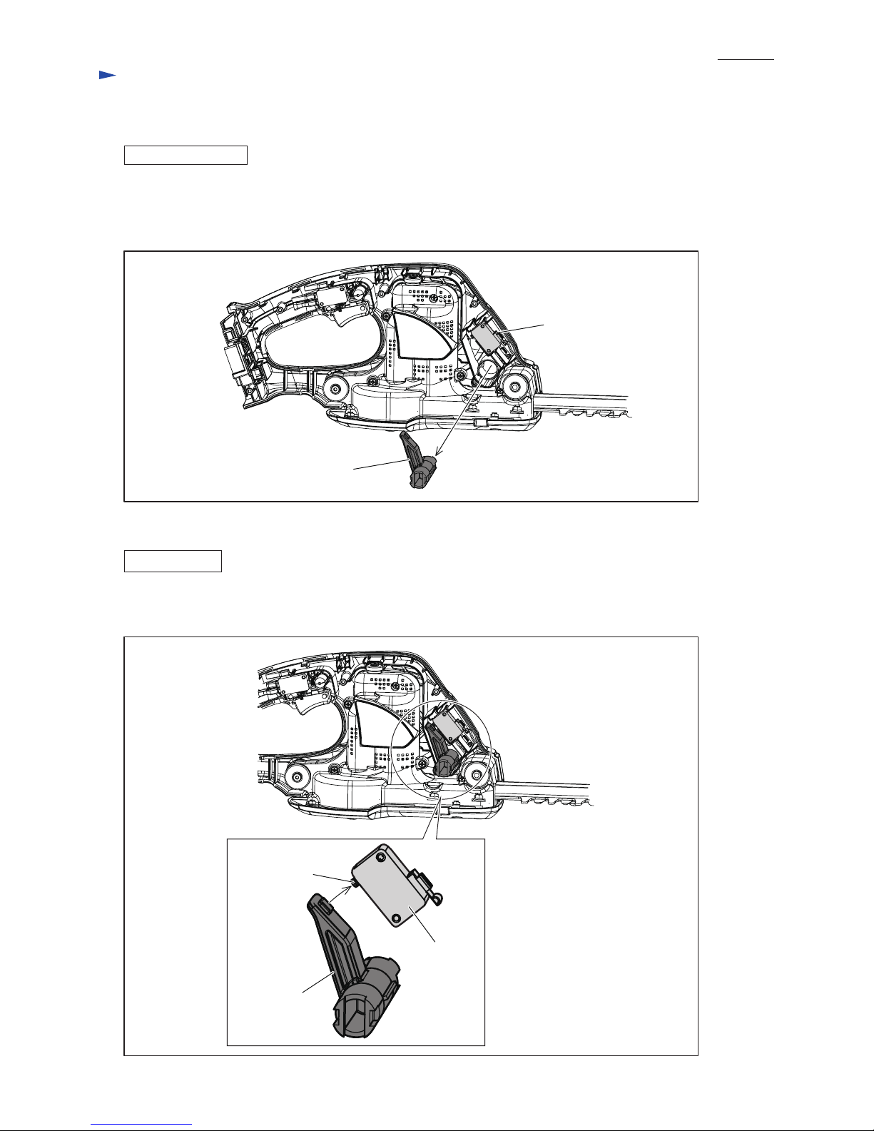
Fig. 15
Fig. 16
[3] DISASSEMBLY/ASSEMBLY
[3] -5. Switch arm
DISASSEMBLING
(1) Disassemble Front grip section as drawn in Fig. 4.
(2) Remove Housing R as drawn in Fig. 5.
(3) Switch arm is removed as drawn in Fig. 15.
Switch arm has to be assembled to Housing L so that it can push ON/OFF button of Switch to link with
Switch lever B’s action. See Fig. 16.
Switch arm
Switch
ASSEMBLING
Switch
ON / OFF
Button
Switch arm
Repair
P 9/ 13
Page 10

Circuit diagram
Fig. D-1
White
LED (Warning lamp for battery)
LED (Warning lamp for battery)
Orange
Purple
Yellow
Color index of lead wires' sheath
Black
Switch
Tape for bundling
Lead wires
Tape for bundling
Lead wires
Line filter
Switch in
rear grip
COM
Switch
lever B side
DC motor
to DC motor
to Terminal
to Switch in Front
grip
Controller
Controller
Terminal
Model No. Power source Battery
Red
BUH483/ 523
BUH481/ 521 BL1415, BL1430 14.4 V
BL1815, BL1830 18 V
Red dot mark
White lead wire is used
for some countries.
Line filter
to AS Terminal
AS
Switch
in front
grip
to Switch in Rear grip
P 10/ 13
Line filter is not used
for some countries.
Line filter is not used
for some countries.
Page 11

Fig. D-2
White
Orange
Purple
Yellow
Color index of lead wires' sheath
Black
Switch
Tape for bundling
Lead wires
Tape for bundling
Lead wires
Switch in
rear grip
Switch
lever B side
DC motor
to DC motor
to minus pole
of Terminal
Controller
Controller
Terminal
Red
BL1811G 18V
to AS Terminal
Switch
in front
grip
Red dot mark
LED (Warning lamp for battery)
Line filter
White lead wire is used
for some countries.
Line filter is not used
for some countries.
AS
Circuit diagram (cont.)
P 11/ 13
COM
Model No. Power source Battery
UH422D/ 482D/ 522D
UH520D
BL1411G 14.4V
LED (Warning lamp for battery)
to Switch in Front
grip
to Switch in Rear grip
Line filter
Line filter is not used
for some countries.
Page 12

Wiring to DC motor
Fig. D-3
Fig. D-4
Lead wire (red)
Face Lead wires (red, black) to Motor housing L
side and connect their connectors with Terminals
of DC motor.
Connect Lead wire (red) to the
connecting terminal near
Red dot mark.
Lead wire (black)
Red dot mark
Connectors
Wiring in Motor housing L
Motor housing L side
Controller side
DC motor
Controller
Rib A
Pass Controller’s Lead wires (6 pcs.)
between Rib A and Rib B to prevent
them from being put on the Ribs.
Face black Lead wire to Controller side
and set DC motor to Motor housing L.
Rib B
Motor housing L
Lead wire (red) between Controller
and DC motor has to be routed between
Boss and inner wall of Motor housing L.
Boss
Tape for
bundling
Lead wires
Bearing box
Bearing box
Wiring diagram
P 12/ 13
Line filter
Put Line filter in this
position if it is used.
Page 13
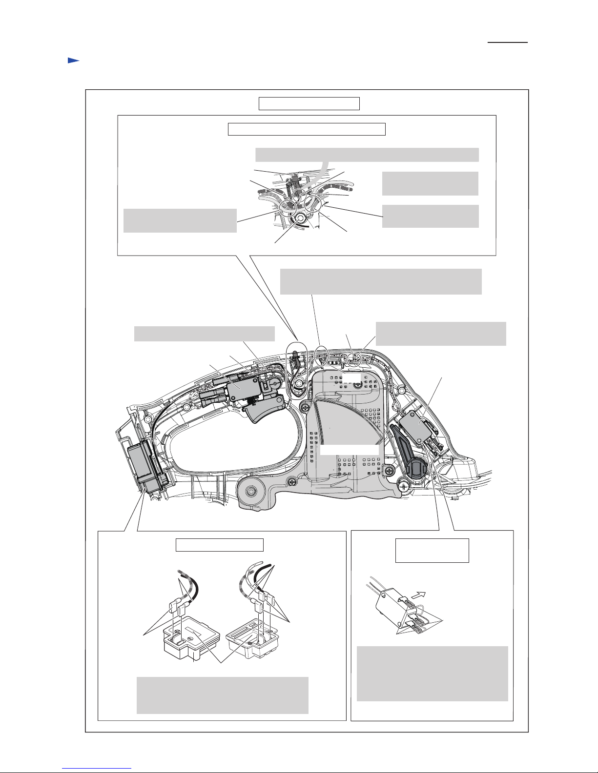
Wiring in Housing set
Fig. D-5
Lead wire
holder
Fix the Lead wires (white, orange,
purple) with Lead wire holder.
Switch on Front
grip side
Wiring to Switch
on Front grip side
Switch
Do not put the Lead wires on this Rib.
Motor housing
Rib
Rib
Face their connectors to Housing L side
and connect their lead wires to Switch
terminals.
Their lead wires have to be routed
between Housing L and Switch.
Connectors
Receptacle
Housing L side
Wiring of LED warning lamp for battery
Rib A
LED Lamp
Rib C
Groove
Face the projected portion of LED Lamp to Front grip side.
Boss
Put LED Lamp’s Lead
wires into groove.
Put the following Lead wires
between Rib A and Boss.
Put Lead wires between
Rib B and Rib C.
Wiring to Terminal
Flag connectors have to be connected so that
their lead wires are passed over the center of
Terminal.
Flag connector
Lead wires
Lead wires
the center of Terminal
Flag connector
Rib B
Route the Lead wires (white, orange, purple) between
the Rib and inner wall of Housing set.
Wiring diagram (cont.)
P 13/ 13
 Loading...