

Page 1
GB Impact Driver Instruction manual
F
Visseuse à chocs
D Schlagschrauber Betriebsanleitung
I Avvitatore a massa battente Istruzioni per l’uso
NL Slagschroevendraaier Gebruiksaanwijzing
E Atornillador de impacto Manual de instrucciones
P Berbequim de impacto Manual de instruções
DK Slagskruetrækker Brugsanvisning
GR Κρουστικό Κατσαβίδι Οδηγίες χρήσης
Manuel d’instructions
TD0101
TD0101F
Page 2
2
1
12
A
3
B
34
4
5
4
6
5
56
7
2
Page 3
.
.
N m
(kgf.cm)
120
(1224)
100
(1020) M14
80
(816)
60
810
(612)
40
(408)
20
(204)
0
1.0
M8
7
M12
M14
M10
M12
M10
M8
3.0
2.0
9
N m
(kgf.cm)
100
(1020)
80
(816)
60
810
(612)
40
(408)
20
(204)
0
1.0
M8
11
M10
M10
M8
2.0
3.0
9
89
13
12
14
10 11
17
15
16
12 13
18
19
3
Page 4
ENGLISH
Explanation of general view
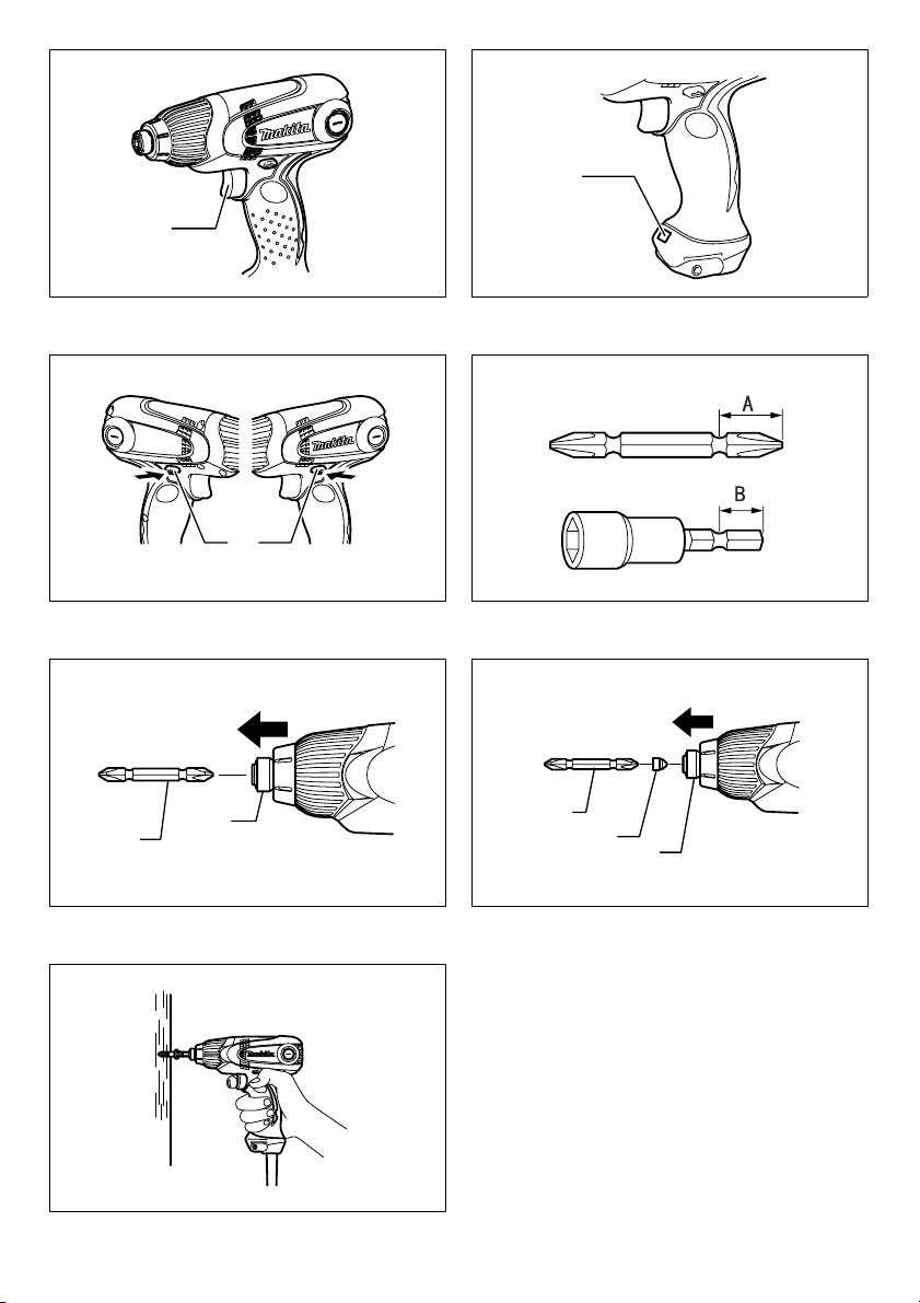
1. Switch trigger
2. Lamp
3. Reversing switch lever
4. Bit
5. Sleeve
6. Bit-piece
7. Standard bolt
8. Fastening torque
9. Fastening time (S)
10. Proper fastening torque
11. High tensile bolt
12. Limit mark
13. Screwdriver
14. Brush holder cap
15. Screw
16. Hook
17. Groove
18. Bumper
19. Hammer case cover
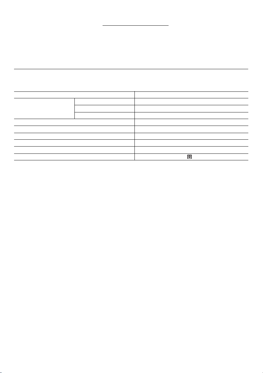
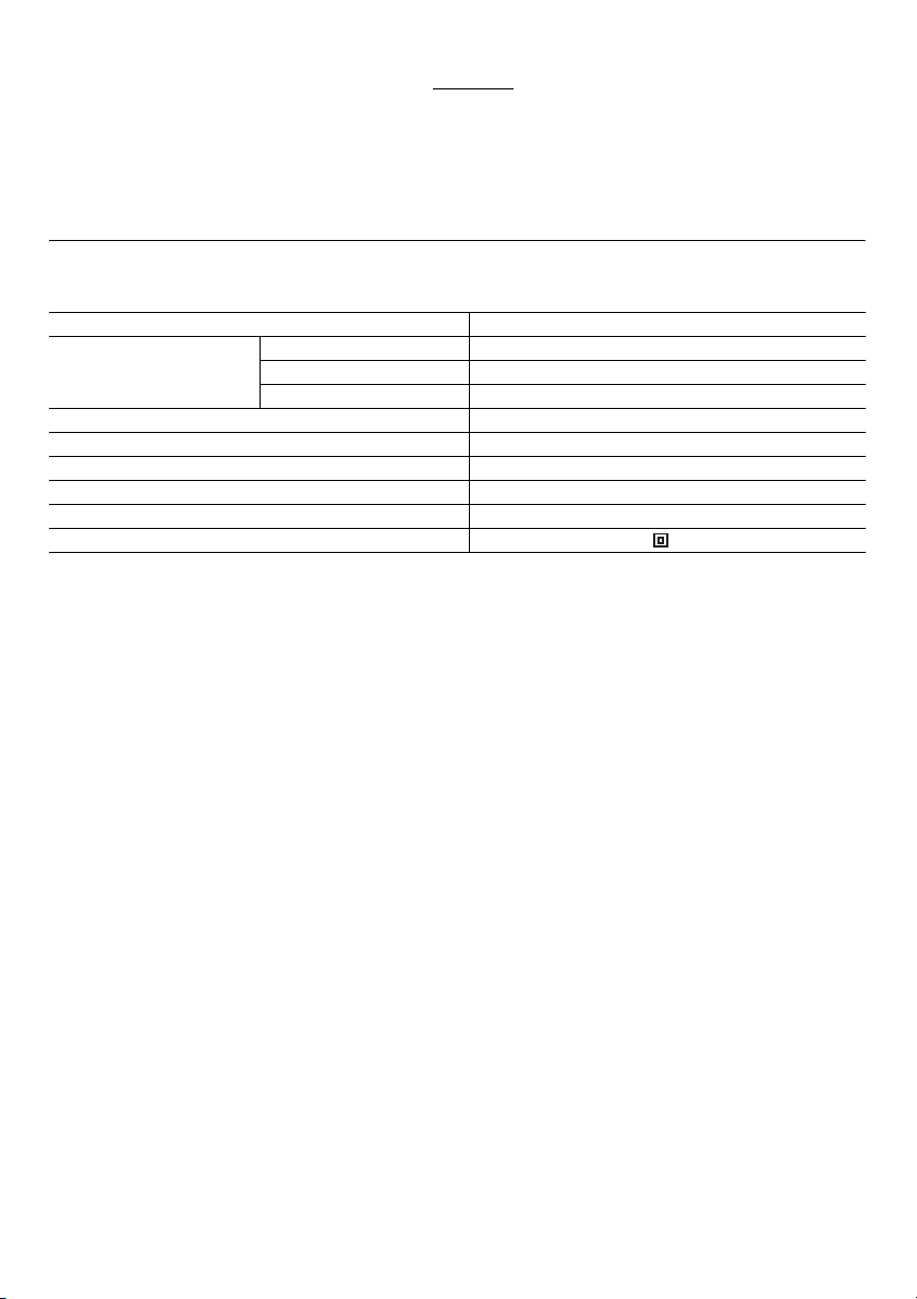
SPECIFICATIONS
Model TD0101/TD0101F
Machine screw 4 mm - 8 mm
Capacities
No load speed (min
Impacts per minute (min
Max. fastening torque 100 N•m
Dimensions (L x W x H) 184 mm x 67 mm x 192 mm
Net weight 0.99 kg
Safety class /II
• Due to our continuing programme of research and development, the specifications herein are subject to change without
notice.
• Note: Specifications may differ from country to country.
• Weight according to EPTA-Procedure 01/2003
Intended use
The tool is intended for screw driving in wood, metal and
plastic.
Power supply
The tool should be connected only to a power supply of
the same voltage as indicated on the nameplate, and can
only be operated on single-phase AC supply. They are
double-insulated in accordance with European Standard
and can, therefore, also be used from sockets without
earth wire.
SPECIFIC SAFETY RULES GEB012-3
DO NOT let comfort or familiarity with product (gained
from repeated use) replace strict adherence to impact
driver safety rules. If you use this tool unsafely or
incorrectly, you can suffer serious personal injury.
1. Hold power tool by insulated gripping surfaces,
when performing an operation where the fastener
may contact hidden wiring or its own cord.
Fasteners contacting a “live” wire may make exposed
metal parts of the power tool “live” and could give the
operator an electric shock.
2. Always be sure you have a firm footing.
Be sure no one is below when using the tool in
high locations.
3. Hold the tool firmly.
4. Wear ear protectors.
Standard bolt 5 mm - 14 mm
High tensile bolt 5 mm - 10 mm
-1
) 0 - 3,600
-1
) 0 - 3,200
ENE033-1
ENF002-1
SAVE THESE INSTRUCTIONS.
WARNING:
MISUSE or failure to follow the safety rules stated in
this instruction manual may cause serious personal
injury.
FUNCTIONAL DESCRIPTION
CAUTION:
• Always be sure that the tool is switched off and
unplugged before adjusting or checking function on the
tool.
Switch action (Fig. 1)
CAUTION:
• Before plugging in the tool, always check to see that
the switch trigger actuates properly and returns to the
“OFF” position when released.
To start the tool, simply pull the switch trigger. Tool speed
is increased by increasing pressure on the switch trigger.
Release the switch trigger to stop.
Lighting up the lamp (Model TD0101F
only) (Fig. 2)
CAUTION:
• Do not look in the light or see the source of light
directly.
Connect the plug to light up the lamp. The lamp keeps on
lighting while the plug is connected.
4
Page 5
NOTE:
• Use a dry cloth to wipe the dirt off the lens of lamp. Be
careful not to scratch the lens of lamp, or it may lower
the illumination.
• Do not use thinner or gasoline to clean the lamp. Such
solvents may damage it.
Reversing switch action (Fig. 3)
• This tool has a reversing switch to change the direction
of rotation. Depress the reversing switch lever from the
A side for clockwise rotation or from the B side for
counterclockwise rotation.
CAUTION:
• Always check the direction of rotation before operation.
• Use the reversing switch only after the tool comes to a
complete stop. Changing the direction of rotation
before the tool stops may damage the tool.
ASSEMBLY
CAUTION:
• Always be sure that the tool is switched off and
unplugged before carrying out any work on the tool.
Installing or removing driver bit or socket
bit (Fig. 4)
Use only bits that has inserting portion shown in the
figure.
For European and North & South American countries,
Australia and New Zealand
A=12 mm
B=9 mm
For other countries
A=17 mm
B=14 mm
A=12 mm
B=9 mm
1. To install the bit, pull the sleeve in the direction of the
arrow and insert the bit into the sleeve as far as it will
go. Then release the sleeve to secure the bit. (Fig.5)
2. To install the bit, pull the sleeve in the direction of the
arrow and insert the bit-piece and bit into the sleeve
as far as it will go. The bit-piece should be inserted
into the sleeve with its pointed end facing in. Then
release the sleeve to secure the bit. (Fig. 6)
To remove the bit, pull the sleeve in the direction of the
arrow and pull the bit out firmly.
NOTE:
• If the bit is not inserted deep enough into the sleeve,
the sleeve will not return to its original position and the
bit will not be secured. In this case, try re-inserting the
bit according to the instructions above.
Use only these type of bit. Follow the
procedure (1).
(Note) Bit-piece is not necessary.
To install these types of bits, follow the
procedure (1).
(Note) Makita bits are these types.
To install these types of bits, follow the
procedure (2).
(Note) Bit-piece is necessary for installing
the bit.
OPERATION (Fig. 7)
NOTE:
• The size of wood screw which can be fastened with this
tool may differ depending upon the type of material to
be fastened. Always perform a test operation to
determine the size of wood screw.
Holding the tool
Hold the tool only by the handle when performing an
operation. Do not touch the metal part.
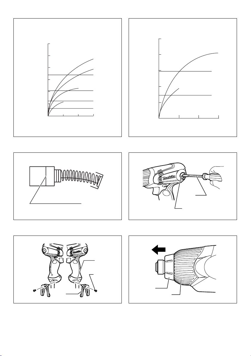
The proper fastening torque may differ depending upon
the kind or size of the screw/bolt, the material of the
workpiece to be fastened, etc. The relation between
fastening torque and fastening time is shown in the
figures. (Fig. 8 & 9)
Hold the tool firmly and place the point of the driver bit in
the screw head. Apply forward pressure to the tool to the
extent that the bit will not slip off the screw and turn the
tool on to start operation.
NOTE:
• Use the proper bit for the head of the screw/bolt that
you wish to use.
• When fastening screw M8 or smaller, carefully adjust
pressure on the switch trigger so that the screw is not
damaged.
• Hold the tool pointed straight at the screw.
• If you tighten the screw for a time longer than shown in
the figures, the screw or the point of the driver bit may
be overstressed, stripped, damaged, etc. Before
starting your job, always perform a test operation to
determine the proper fastening time for your screw.
The fastening torque is affected by a wide variety of
factors including the following. After fastening, always
check the torque with a torque wrench.
1. Driver bit or socket bit
Failure to use the correct size driver bit or socket bit
will cause a reduction in the fastening torque.
2. Bolt
• Even though the torque coefficient and the class of
bolt are the same, the proper fastening torque will
differ according to the diameter of bolt.
• Even though the diameters of bolts are the same,
the proper fastening torque will differ according to
the torque coefficient, the class of bolt and the bolt
length.
3. The manner of holding the tool or the material of
driving position to be fastened will affect the torque.
4. Operating the tool at low speed will cause a reduction
in the fastening torque.
MAINTENANCE
CAUTION:
• Always be sure that the tool is switched off and
unplugged before attempting to perform inspection or
maintenance.
Replacing carbon brushes (Fig. 10)
Remove and check the carbon brushes regularly. Replace
when they wear down to the limit mark. Keep the carbon
brushes clean and free to slip in the holders. Both carbon
5
Page 6
brushes should be replaced at the same time. Use only
identical carbon brushes.
Use a screwdriver to remove the brush holder caps. Take
out the worn carbon brushes, insert the new ones and
secure the brush holder caps. (Fig. 11)
To maintain product SAFETY and RELIABILITY, repairs,
carbon brush inspection and replacement, any other
maintenance or adjustment should be performed by
Makita Authorized Service Centers, always using Makita
replacement parts.
ACCESSORIES
CAUTION:
• These accessories or attachments are recommended
for use with your Makita tool specified in this manual.
The use of any other accessories or attachments might
present a risk of injury to persons. Only use accessory
or attachment for its stated purpose.
If you need any assistance for more details regarding
these accessories, ask your local Makita Service Center.
• Screw bits
• Socket bits
• Bit piece
• Adjustable locator with bit
•Hook
Hook (Fig. 12)
The hook is convenient for temporarily hanging the tool.
This can be installed on either side of the tool.
To install the hook, insert it into a groove in the tool
housing on either side and then secure it with a screw. To
remove, loosen the screw and then take it out.
Adjustable locator with bit (Fig. 13)
To use the adjustable locator with bit, remove the bumper
and then install it. The bumper can be removed by pulling
forward.
For European countries only
Noise
ENG102-1
The typical A-weighted noise level determined according
to EN60745-2-2:
Sound pressure level (L
Sound power level L
Uncertainty (K): 3 dB (A)
): 90 dB (A)
pA
): 101 dB (A)
WA
Wear ear protection
Vibration
ENG205-1
The vibration total value (tri-axial vector sum) determined
according to EN60745-2-2:
Work mode: impact tightening of fasteners of the
maximum capacity of the tool
Vibration emission (a
Uncertainty (K): 1.5 m/s
h
): 7.5 m/s
2
2
EC-DECLARATION OF CONFORMITY ENH101-9
Model; TD0101, TD0101F
We declare under our sole responsibility that this product
is in compliance with the following standards of
standardized documents;
EN60745, EN55014, EN61000 in accordance with
Council Directives, 2004/108/EC, 98/37/EC.
CE 2008
Tomoyasu Kato
Director
Responsible Manufacturer:
Makita Corporation
3-11-8, Sumiyoshi-cho, Anjo, Aichi, JAPAN
Authorized Representative in Europe:
Makita International Europe Ltd.
Michigan Drive, Tongwell, Milton Keynes, Bucks MK15
8JD, ENGLAND
6
Page 7
FRANÇAIS
Descriptif
1. Gâchette
2. Lampe
3. Levier inverseur
4. Embout
5. Manchon
6. Partie de l’embout
7. Boulon standard
8. Couple de serrage
9. Temps de serrage (S)
10. Couple de serrage adéquat
11. Boulon haute résistance
12. Repère d’usure
13. Tournevis
14. Bouchon de porte-charbon
15. Vis
16. Crochet
17. Rainure
18. Butoir
19. Couvercle de carter du mouton
SPÉCIFICATIONS
Modèle TD0101/TD0101F
Vis de mécanique 4 à 8 mm
Capacités
Vitesse à vide (min
Impacts par minute (min
Couple de serrage max. 100 N•m
Dimensions (L x P x H) 184 mm x 67 mm x 192 mm
Poids net 0,99 kg
Niveau de sécurité /II
• Étant donné l’évolution constante de notre programme de recherche et de développement, les spécifications
contenues dans ce manuel sont sujettes à des modifications sans préavis.
• Remarque : les spécifications peuvent varier d’un pays à l’autre.
• Poids conforme à la procédure EPTA 01/2003
Usage prévu
L'outil est conçu pour visser dans du bois, du métal et du
plastique.
Alimentation
L’outil ne doit être raccordé qu’à une alimentation de la
même tension que celle qui figure sur la plaque
signalétique, et il ne peut fonctionner que sur un courant
secteur monophasé. Réalisé avec une double isolation, il
est conforme à la réglementation européenne et peut de
ce fait être alimenté sans mise à la terre.
CONSIGNES DE SÉCURITÉ
SPÉCIFIQUES GEB012-3
NE vous laissez PAS tromper (au fil d’une utilisation
répétée) par un sentiment d’aisance et de familiarité
avec le produit, en négligeant le respect rigoureux
des consignes de sécurité qui accompagnent l’outil.
En utilisant cet outil dans des conditions
dangereuses ou incorrectes, vous vous exposez à un
risque de blessure grave.
1. Tenez l’outil électrique par ses surfaces de poigne
isolées lorsque vous effectuez une opération au
cours de laquelle la pièce de fixation peut entrer
en contact avec des fils dissimulés ou avec le
cordon de l’outil. Il est possible que les pièces de
fixation entrant en contact avec un fil sous tension
mettent les parties métalliques exposées de l’outil
sous tension, risquant ainsi de provoquer un choc
électrique chez l’utilisateur.
Boulon standard 5 à 14 mm
Boulon haute résistance 5 à 10 mm
-1
) 0 - 3 600
-1
) 0 - 3 200
ENE033-1
ENF002-1
2. Veillez à toujours avoir une bonne position
d’équilibre.
Assurez-vous que personne ne se trouve dessous
lorsque vous utilisez l’outil en position élevée.
3. Tenez l’outil fermement.
4. Portez des protections auditives.
CONSERVEZ CES
INSTRUCTIONS.
AVERTISSEMENT:
Une UTILISATION INCORRECTE de l’outil ou un nonrespect des consignes de sécurité indiquées dans ce
manuel d’instructions peuvent causer des blessures
graves.
DESCRIPTION DU
FONCTIONNEMENT
ATT EN TIO N :
• Assurez-vous toujours que l’outil est éteint et
débranché avant de le régler ou de vérifier son
fonctionnement.
Interrupteur (Fig. 1)
ATT EN TIO N :
• Avant de brancher l’outil, vérifiez toujours que la
gâchette fonctionne correctement et revient en position
d’arrêt (« OFF ») lorsqu’elle est relâchée.
Pour mettre l’outil en marche, appuyez simplement sur la
gâchette. La vitesse de l’outil augmente à mesure que l’on
7
Page 8

accroît la pression exercée sur la gâchette. Pour l’arrêter,
relâchez la gâchette.
Allumage de la lampe (modèle TD0101F
uniquement) (Fig. 2)
ATT EN TIO N :
• Ne regardez pas directement la lumière ou la source
lumineuse.
Branchez la prise pour allumer la lampe. La lampe
demeure allumée tant que l’outil est branché.
REMARQUE :
• Utilisez un chiffon sec pour essuyer les saletés qui
recouvrent la lentille de la lampe. Prenez garde de ne
pas rayer la lentille de la lampe, sinon sa capacité
d’éclairage sera affectée.
• N’utilisez ni diluant ni essence pour nettoyer la lampe.
De tels solvants risqueraient de l’endommager.
Marche arrière (Fig. 3)
• L’outil possède un inverseur qui permet de changer le
sens de rotation. Appuyez sur le levier de l’inverseur
depuis le côté A pour une rotation dans le sens des
aiguilles d’une montre, ou depuis le côté B pour une
rotation en sens inverse.
ATT EN TIO N :
• Vérifiez toujours le sens de rotation avant de mettre
l’outil en marche.
• N’actionnez l’inverseur qu’une fois l’outil complètement
arrêté. Si vous changez le sens de rotation de l’outil
avant l’arrêt de celui-ci, vous risquez de l’endommager.
ASSEMBLAGE
ATT EN TIO N :
• Avant d’effectuer toute intervention sur l’outil, assurezvous toujours qu’il est hors tension et débranché.
Pour installer ou retirer l’embout ou
l’embout à douille (Fig. 4)
N’utilisez que des embouts qui ont une partie qui s’insère
comme illustré sur la figure.
Pour les pays d’Europe, d’Amérique du nord et du
sud, l’Australie et la Nouvelle-Zélande
A=12 mm
B=9 mm
Pour les autres pays
A=17 mm
B=14 mm
A=12 mm
B=9 mm
1. Pour installer l’embout, tirez le manchon dans le sens
de la flèche et insérez l’embout dans le manchon
8
N’utilisez que ces types d’embouts. Suivez
la procédure (1).
(Remarque) la partie de l’embout n’est pas
nécessaire.
Pour installer ces types d’embouts suivez la
procédure (1).
(Remarque) les embouts Makita
correspondent à ces types.
Pour installer ces types d’embouts suivez la
procédure (2).
(Remarque) la partie d’embout est
nécessaire pour installer l’embout.
aussi profondément que possible. Relâchez ensuite le
manchon pour sécuriser l’embout. (Fig.5)
2. Pour installer l’embout, tirez le manchon dans le sens
de la flèche et insérez l’embout dans le manchon
aussi profondément que possible. La partie de
l’embout doit être insérée dans le manchon avec son
extrémité pointée face à l’entrée. Puis libérez le
manchon pour serrer l’embout. (Fig. 6)
Pour enlever l’embout, tirez le manchon dans le sens de
la flèche et tirez sur l’embout avec fermeté.
REMARQUE :
• Si l’embout n’est pas inséré assez profondément dans
le manchon, ce dernier ne retournera pas à sa position
d’origine et l’embout ne sera pas sécurisé. Dans ce
cas, essayez de réinsérer l’embout selon les
instructions précédentes.
UTILISATION (Fig. 7)
REMARQUE :
• La dimension de la vis à bois qui peut être fixée sur cet
outil peut varier en fonction du type de matériau à fixer.
Effectuez toujours un test pour déterminer la dimension
de la vis à bois.
Manipulation de l’outil
Manipulez l’outil uniquement par la poignée lors de son
utilisation. Ne touchez pas la partie métallique.
Le couple de serrage adéquat peut varier selon le type ou
la taille de la vis/du boulon, le matériau de la pièce de
travail à fixer, etc. Le rapport entre le couple et la durée de
serrage est illustré sur les figures. (Fig. 8 et 9)
Tenez fermement l’outil et placez la pointe de l’embout
dans la tête de la vis. Appliquez une pression sur l’outil
vers l’avant de sorte que l’embout ne glisse pas de la vis
et démarrez l’outil pour commencer le travail à effectuer.
REMARQUE :
• Utilisez l’embout approprié pour la tête de la vis/du
boulon que vous souhaitez utiliser.
• Quand vous fixez des vis M8 ou plus petites, réglez
soigneusement la pression sur la gâchette de sorte
que la vis ne soit pas endommagée.
• Maintenez l’outil pointé tout droit sur la vis.
• Si vous serrez la vis plus longtemps que le temps
indiqué dans les tableaux, la vis ou la pointe de
l’embout peut être surexploitée, foirée, endommagée,
etc. Avant de commencer votre travail, faites toujours
un essai pour déterminer la durée de serrage correcte
pour votre vis.
Le couple de serrage dépend de nombreux facteurs, dont
les suivants. Après le serrage, vérifiez toujours le couple
avec une clé dynamométrique.
1. Embout ou embout à douille
Si vous n’utilisez pas un embout ou un embout à
douille de taille appropriée, cela entraînera une
diminution du couple de serrage.
2. Boulon
• Pour un même coefficient de couple et une même
classe de boulon, le couple de serrage adéquat
varie suivant le diamètre du boulon.
• Bien que les diamètres des boulons soient
identiques, le couple de serrage approprié différera
Page 9
en fonction du coefficient de couple ; de la classe et
de la longueur du boulon.
3. Le couple est affecté par la façon dont l’outil est tenu
ou par le matériau à serrer.
4. Le fonctionnement de l’outil à une vitesse lente
entraînera une réduction du couple de serrage.
MAINTENANCE
ATT EN TIO N :
• Assurez-vous toujours que l’outil est éteint et
débranché avant d’effectuer tout travail d’inspection ou
de maintenance.
Remplacement des charbons (Fig. 10)
Retirez et vérifiez les charbons régulièrement.
Remplacez-les lorsqu’ils atteignent le repère d’usure.
Gardez les charbons propres et libres de glisser dans les
porte-charbons. Les deux charbons doivent être
remplacés en même temps. Utilisez uniquement des
charbons identiques.
Retirez les bouchons de porte-charbon à l’aide d’un
tournevis. Enlevez les charbons usés, insérez les neufs et
remettez en place les bouchons de porte-charbon.
(Fig. 11)
Pour assurer la SÉCURITÉ et la FIABILITÉ du produit,
toute réparation, inspection et remplacement des
charbons, ainsi que toute autre tâche de maintenance ou
de réglage, doivent être effectués par un Centre de
service agréé Makita, toujours avec des pièces de
rechange Makita.
ACCESSOIRES
ATT EN TIO N :
• Ces accessoires ou pièces complémentaires sont
recommandés pour l’utilisation avec l’outil Makita
spécifié dans ce manuel. L’utilisation de tout autre
accessoire ou pièce complémentaire comporte un
risque de blessures. Utilisez uniquement l’accessoire
ou la pièce complémentaire dans le but spécifié.
Pour obtenir plus de détails sur ces accessoires,
contactez votre Centre de service après-vente Makita le
plus proche.
• Embouts
• Embouts à douille
• Partie d’embout
• Centreur réglable avec embout
• Crochet
Crochet (Fig. 12)
L’outil est équipé d’un crochet pratique qui permet de le
suspendre temporairement. Il s’installe d’un côté comme
de l’autre de l’outil.
Pour installer le crochet, insérez-le dans une rainure du
carter de l’outil d’un côté ou de l’autre puis serrez-le avec
une vis. Pour le retirer, desserrez la vis et enlevez-le.
Centreur réglable avec embout (Fig. 13)
Pour utiliser le centreur réglable avec embout, retirez le
butoir, puis installez-le. Vous pouvez également retirer le
butoir en tirant dessus.
Pour les pays européens uniquement
Bruit
Niveau de bruit pondéré A typique déterminé selon
la norme EN60745-2-2 :
Niveau de pression sonore (L
Niveau de puissance sonore (L
Incertitude (K) : 3 dB (A)
Portez des protections auditives
Vibration
La valeur totale de vibration (somme du vecteur triaxial)
déterminée selon EN60745-2-2 :
Mode de fonctionnement : serrage par impact des
pièces de fixation de la
capacité maximale de l’outil
Émission des vibrations (a
Incertitude (K) : 1,5 m/s
DÉCLARATION DE CONFORMITÉ CE ENH101-9
Modèle ; TD0101, TD0101F
Nous déclarons, sous notre entière responsabilité, que ce
produit répond aux normes suivantes de documents
normalisés ;
EN60745, EN55014, EN61000 conformément aux
Directives du Conseil, 2004/108/CE, 98/37/CE.
CE 2008
Tomoyasu Kato
Directeur
Fabricant responsable :
Makita Corporation
3-11-8, Sumiyoshi-cho, Anjo, Aichi, JAPON
Représentant agréé en Europe :
Makita International Europe Ltd.
Michigan Drive, Tongwell, Milton Keynes, Bucks MK15
8JD, ANGLETERRE
): 7,5m/s
h
2
) : 90 dB (A)
pA
) : 101 dB (A)
WA
ENG102-1
ENG205-1
2
9
Page 10
DEUTSCH
Erklärung der Gesamtdarstellung
1. Ein/Aus-Schalter
2. Lampe
3. Umschalthebel
4. Einsatz
5. Kranz
6. Einsatzteil
7. Standardschraube
8. Anzugsmoment
9. Anzugszeit (s)
10. Richtiges Anzugsmoment
11. Hochfeste vorgespannte
Schraube
12. Verschleißmarkierung
13. Schraubendreher
14. Bürstenhalterkappe
15. Schraube
16. Haken
17. Rille
18. Stoßfänger
19. Abdeckung Schlagwerk
TECHNISCHE DATEN
Modell TD0101/TD0101F
Maschinenschraube 4 bis 8 mm
Schraubvermögen
Leerlaufdrehzahl (U/min
Schläge pro Minute (min
Max. Anzugsmoment 100 Nm
Abmessungen (L x B x H) 184 mm x 67 mm x 192 mm
Nettogewicht 0,99 kg
Sicherheitsklasse /II
• Aufgrund unserer weiterführenden Forschungen und Entwicklungen sind Änderungen an den hier angegebenen
Technischen Daten ohne Vorankündigung vorbehalten.
• Hinweis: Die Technischen Daten können in den einzelnen Ländern abweichen.
• Gewicht entsprechend der EPTA-Vorgehensweise 01/2003
Verwendungszweck
Das Werkzeug wurde für das Schrauben in Holz, Metall
und Kunststoff entwickelt.
Stromversorgung
Das Werkzeug darf nur an eine Stromversorgung mit der
auf dem Typenschild angegebenen Spannung und
einphasigem Wechselstrom angeschlossen werden.
Aufgrund der Doppelisolierung nach europäischem
Standard kann das Werkzeug auch an Steckdosen ohne
Erdungsleiter betrieben werden.
BESONDERE
SICHERHEITSREGELN GEB012-3
Lassen Sie sich NIE durch Bequemlichkeit oder (aus
fortwährendem Gebrauch gewonnener) Vertrautheit
mit dem Gerät dazu verleiten, die Sicherheitsregeln
für den Umgang mit diesem Werkzeug zu missachten.
Wenn dieses Werkzeug fahrlässig oder nicht
ordnungsgemäß verwendet wird, kann es zu
schweren Verletzungen kommen.
1. Halten Sie das Elektrowerkzeug an den isolierten
Griffflächen, wenn Sie unter Bedingungen
arbeiten, bei denen das Schneidwerkzeug
verborgene Verkabelung oder das eigene Kabel
berühren kann. Bei Kontakt des Trennwerkzeugs mit
einem Strom führenden Kabel wird der Strom an die
Metallteile des Elektrowerkzeugs und dadurch an den
Bediener weitergeleitet, und der Bediener erleidet
einen Stromschlag.
Standardschraube 5 bis 14 mm
Hochfeste vorgespannte
Schraube
-1
) 0 - 3.600
-1
) 0 - 3.200
ENE033-1
ENF002-1
2. Achten Sie jederzeit auf einen festen Stand.
Achten Sie bei Verwendung des Werkzeugs an
erhöhten Standorten darauf, dass sich keine
Personen unter dem Standort aufhalten.
3. Halten Sie das Werkzeug mit festem Griff.
4. Tragen Sie Gehörschutz.
5 bis 10 mm
BEWAHREN SIE DIESE
ANLEITUNG SORGFÄLTIG AUF.
WARNUNG:
Eine MISSBRÄUCHLICHE Verwendung des
Werkzeugs und die Missachtung der in diesem
Handbuch enthaltenen Sicherheitshinweise können
zu schweren Verletzungen führen.
FUNKTIONSBESCHREIBUNG
VORSICHT:
• Schalten Sie das Werkzeug stets aus und ziehen Sie
den Stecker, bevor Sie Einstellungen oder eine
Funktionsprüfung am Werkzeug vornehmen.
Bedienung des Schalters (Abb. 1)
VORSICHT:
• Achten Sie vor dem Einstecken des Netzsteckers des
Werkzeugs in die Steckdose darauf, dass sich der Ein/
Aus-Schalter korrekt bedienen lässt und beim
Loslassen in die Position „OFF“ (AUS) zurückkehrt.
10
Page 11

Betätigen Sie zum Starten des Werkzeugs einfach den
Ein/Aus-Schalter. Die Drehzahl des Werkzeugs wird
durch erhöhten Druck auf den Ein/Aus-Schalter
gesteigert. Lassen Sie zum Ausschalten des Werkzeugs
den Ein/Aus-Schalter los.
Einschalten der Lampe (nur Modell
TD0101F) (Abb. 2)
VORSICHT:
• Schauen Sie nicht direkt in das Licht oder in die
Lichtquelle.
Schließen Sie zum Einschalten der Lampe den Stecker
an. Die Lampe leuchtet, während der Stecker an die
Stromversorgung angeschlossen ist.
HINWEIS:
• Wischen Sie Schmutz auf der Lampenlinse mit einem
trockenen Tuch ab. Achten Sie darauf, die
Lampenlinse nicht zu zerkratzen, da dies die
Beleuchtungsstärke mindern kann.
• Verwenden Sie zum Reinigen der Lampe weder
Verdünnung noch Benzin. Die Lampe kann durch diese
Lösungsmittel beschädigt werden.
Bedienung des Umschalters (Abb. 3)
• Dieses Werkzeug verfügt über einen Umschalter, mit
dem die Drehrichtung geändert werden kann. Für eine
Drehbewegung im Uhrzeigersinn muss der
Umschalthebel von der Seite A nach unten gedrückt
werden, und für eine Drehbewegung gegen den
Uhrzeigersinn von der Seite B.
VORSICHT:
• Überprüfen Sie vor jedem Betrieb immer die
Drehrichtung.
• Der Umschalter darf nur betätigt werden, wenn das
Werkzeug im Stillstand ist. Wenn Sie die Drehrichtung
bei noch laufendem Werkzeug umschalten, kann das
Werkzeug beschädigt werden.
MONTAGE
VORSICHT:
• Schalten Sie das Werkzeug stets aus und ziehen Sie
den Netzstecker, bevor Sie irgendwelche Arbeiten am
Werkzeug durchführen.
Einsetzen und Entfernen des Schraubenoder Steckeinsatzes (Abb. 4)
Verwenden Sie ausschließlich Einsätze mit einem in der
Abbildung dargestellten Montagekopf.
Für Europa, Nord- und Süd-Amerika, Australien und
Neuseeland
A = 12 mm
B = 9 mm
Für andere Länder
A = 17 mm
B = 14 mm
A = 12 mm
B = 9 mm
1. Zum Einsetzen des Einsatzes in das Werkzeug ziehen
2. Zum Einsetzen des Einsatzes in das Werkzeug ziehen
Zum Entnehmen des Einsatzes ziehen Sie den Kranz in
Pfeilrichtung und ziehen Sie den Einsatz kräftig heraus.
HINWEIS:
• Falls der Einsatz nicht tief genug in den Kranz
eingesetzt wurde, kehrt der Kranz nicht in seine
Ursprungsposition zurück, und der Einsatz ist nicht
gesichert. Setzen Sie in diesem Fall den Einsatz
anhand der oben aufgeführten Anweisungen erneut
ein.
Verwenden Sie ausschließlich diese Art von
Einsätzen. Befolgen Sie die
Vorgehensweise (1).
(Hinweis) Einsatzteil ist nicht erforderlich.
Zum Einsetzen dieser Art von Einsätzen
befolgen Sie die Vorgehensweise (1).
(Hinweis) Makita-Einsätze sind diesen
Typs .
Zum Einsetzen dieser Art von Einsätzen
befolgen Sie die Vorgehensweise (2).
(Hinweis) Einsatzteil ist zum Einsetzen des
Einsatzes erforderlich.
Sie den Kranz in Richtung des Pfeils und setzen Sie
den Einsatz bis zum Anschlag in den Kranz ein.
Lassen Sie den Kranz los, um den Einsatz zu sichern.
(Abb. 5)
Sie den Kranz in Richtung des Pfeils und setzen Sie
das Einsatzteil und den Einsatz bis zum Anschlag in
den Kranz ein. Das Einsatzteil muss mit der Spitze
einwärts in den Kranz eingesetzt werden. Lassen Sie
den Kranz los, um den Einsatz zu sichern. (Abb. 6)
BETRIEB (Abb. 7)
HINWEIS:
• Die Größe der Schrauben, die mit diesem Werkzeug
festgezogen werden können, ist vom zu befestigenden
Material abhängig. Nehmen Sie immer eine
Probeverschraubung vor, um die geeignete Größe der
Holzschraube zu bestimmen.
Halten des Werkzeugs
Halten Sie das Werkzeug bei der Arbeit ausschließlich am
Griff. Berühren Sie nicht den Metallteil.
Das richtige Anzugsdrehmoment kann je nach Art und
Größe der Schraube/des Bolzens, des Materials des zu
befestigenden Werkstücks usw. abweichen. Das
Verhältnis zwischen Anzugsdrehmoment und -zeit ist in
den Abbildungen dargestellt. (Abb. 8 und 9)
Halten Sie das Werkzeug fest und setzen Sie die Spitze
des Schraubeinsatzes in den Schraubenkopf. Üben Sie
so viel Vorwärtsdruck auf das Werkzeug aus, dass der
Einsatz nicht von der Schraube rutscht, und schalten Sie
das Werkzeug ein, um mit dem Betrieb zu beginnen.
11
Page 12

HINWEIS:
• Verwenden Sie den für den Kopf der zu verwendenden
Schrauben/Bolzen passenden Einsatz.
• Üben Sie beim Festziehen von Schrauben der Größe
M8 oder kleiner vorsichtigen Druck auf den
Auslöseschalter aus, um die Schraube nicht zu
beschädigen.
• Halten Sie das Werkzeug direkt und gerade an die
Schraube.
• Wenn Sie die Schraube länger als in den Abbildungen
dargestellt festziehen, kann dies die Schraube oder die
Spitze des Einsatzes überlasten, ausreißen,
beschädigen usw. Bevor Sie mit der Arbeit beginnen,
führen Sie immer eine Probeverschraubung aus, um
die richtige Anzugszeit für die Schraube zu finden.
Das Anzugsmoment wird durch eine Vielzahl von
Faktoren beeinflusst, von denen einige im Folgenden
aufgeführt sind. Prüfen Sie nach dem Festziehen immer
das Drehmoment mit Hilfe eines Drehmomentschlüssels.
1. Schraubeneinsatz oder Steckeinsatz
Wird nicht die richtige Größe für den
Schraubeneinsatz oder den Steckeinsatz ausgewählt,
wird das Anzugsmoment verringert.
2. Schrauben
• Auch wenn der Drehmomentkoeffizient und die
Klasse für die Schrauben übereinstimmen, kann
das Anzugsmoment in Abhängigkeit vom
Durchmesser der Schrauben abweichen.
• Auch wenn die Durchmesser der Bolzen gleich
sind, kann das richtige Anzugsmoment in
Abhängigkeit vom Drehmomentkoeffizienten, der
Klasse und Länge des Bolzens abweichen.
3. Die Weise, wie das Werkzeug gehalten wird, und das
Material an der zu schraubenden Position
beeinflussen das Drehmoment.
4. Der Betrieb des Werkzeugs mit einer niedrigeren
Drehzahl führt zu einer Verringerung des
Anzugsmoments.
Dabei sind ausschließlich Makita-Ersatzteile zu
verwenden.
ZUBEHÖR
VORSICHT:
• Für das in diesem Handbuch beschriebene MakitaWerkzeug werden folgende Zubehör- und Zusatzteile
empfohlen. Bei Verwendung anderer Zubehör- und
Zusatzteile besteht Verletzungsgefahr. Verwenden Sie
Zubehör- und Zusatzteile nur für den vorgesehenen
Zweck.
Informationen zu diesem Zubehör erhalten Sie bei einem
Makita-Servicecenter in Ihrer Nähe.
• Schraubendrehereinsätze
• Steckeinsätze
•Einsatzteil
• Einstellbarer Zentrierring mit Einsatz
• Haken
Einhängeclip (Abb. 12)
Der Haken ist nützlich, wenn Sie das Werkzeug
vorübergehend aufhängen möchten. Die Befestigung
kann an jeder Seite des Werkzeugs erfolgen.
Setzen Sie zur Montage den Haken in eine Rille am
Werkzeuggehäuse (die Seite ist beliebig) und befestigen
Sie diesen mit einer Schraube. Zur Entfernung müssen
Sie nur die Schraube lösen und den Haken
herausnehmen.
Einstellbarer Zentrierring mit Einsatz
(Abb. 13)
Um mit dem einstellbaren Zentrierring mit Einsatz zu
arbeiten, entfernen Sie den Stoßfänger und installieren
Sie den Zentrierring. Der Stoßfänger kann nach vorn
abgezogen werden.
WARTUNG
VORSICHT:
• Schalten Sie das Werkzeug stets aus und ziehen Sie
den Stecker aus der Steckdose, bevor Sie Prüfungen
oder Wartungsarbeiten am Werkzeug durchführen.
Ersetzen der Kohlebürsten (Abb. 10)
Entfernen und überprüfen Sie die Kohlebürsten in
regelmäßigen Abständen. Ersetzen Sie diese, wenn sie
bis zur Verschleißgrenze abgenutzt sind. Halten Sie die
Kohlebürsten sauber und sorgen Sie dafür, dass sie
locker in den Halterungen liegen. Ersetzen Sie beide
Kohlebürsten gleichzeitig. Verwenden Sie nur identische
Kohlebürsten.
Verwenden Sie einen Schraubendreher, um die
Bürstenhalterkappen zu entfernen. Entnehmen Sie die
verbrauchten Kohlebürsten, legen Sie die neuen ein und
bringen Sie die Bürstenhalterkappen wieder fest an.
(Abb. 11)
Um die SICHERHEIT und ZUVERLÄSSIGKEIT des
Produkts zu gewährleisten, dürfen Reparaturen,
Kohlebürsteninspektion und -austausch sowie alle
anderen Wartungsarbeiten und Einstellungen nur in von
Makita autorisierten Servicecentern ausgeführt werden.
12
Page 13

Nur für europäische Länder
Schallpegel
ENG102-1
Die typischen effektiven Geräuschpegel nach
EN60745-2-2:
Schalldruckpegel (L
Schallleistungspegel (L
Abweichung (K): 3 dB (A)
): 90 dB (A)
pA
): 101 dB (A)
WA
Tragen Sie Gehörschutz.
Schwingung
ENG205-1
Schwingungsgesamtwerte (Vektorsumme dreier Achsen)
nach EN60745-2-2:
Arbeitsmodus: Schlagschrauben von
Befestigungsmitteln mit der
maximalen Leistung des Werkzeugs
Schwingungsbelastung (a
Abweichung (K): 1,5 m/s
h
2
): 7,5 m/s
2
EG-KONFORMITÄTSERKLÄRUNG ENH101-9
Modell: TD0101, TD0101F
Wir erklären in alleiniger Verantwortung, dass sich dieses
Produkt in Übereinstimmung mit den folgenden Normen
der Normdokumente
EN60745, EN55014, EN61000 befindet sowie in
Übereinstimmung mit den Ratsverordnungen
2004/108/EC, 98/37/EC .
CE 2008
Tomoyasu Kato
Direktor
Verantwortlicher Hersteller:
Makita Corporation
3-11-8, Sumiyoshi-cho, Anjo, Aichi, JAPAN
Autorisierte Vertretung in Europa:
Makita International Europe Ltd.
Michigan Drive, Tongwell, Milton Keynes, Bucks MK15
8JD, ENGLAND
13
Page 14

ITALIANO
Spiegazione della vista generale
1. Interruttore
2. Lampada
3. Leva di inversione della rotazione
4. Punta
5. Manicotto
6. Componente della punta
7. Bullone standard
8. Coppia di serraggio
9. Tempo di serraggio (S)
10. Coppia di serraggio corretta
11. Bullone altamente tensile
12. Indicatore di limite
13. Cacciavite
14. Coperchio portaspazzola
15. Vite
16. Gancio
17. Scanalatura
18. Paraurti
19. Coperchio alloggiamento martello
CARATTERISTICHE TECNICHE
Modello TD0101/TD0101F
Vite per metallo 4 mm - 8 mm
Capacità di foratura
Velocità a vuoto (min
Impulsi al minuto (min
Coppia di serraggio max. 100 Nm
Dimensioni (L x P x A) 184 mm x 67 mm x 192 mm
Peso netto 0,99 kg
Classe di sicurezza /II
• Le caratteristiche tecniche riportate di seguito sono soggette a modifiche senza preavviso in virtù del nostro
programma continuo di ricerca e sviluppo.
• Nota: le caratteristiche tecniche possono differire da paese a paese.
• Peso determinato in conformità con la EPTA-Procedure 01/2003
Uso previsto
Questo utensile è progettato per l'avvitatura di viti in
legno, metallo e plastica.
Alimentazione
L'utensile deve essere collegato a una presa di corrente
con la stessa tensione di quella indicata sulla targhetta e
può funzionare soltanto con corrente alternata monofase.
L'utensile è dotato di doppio isolamento in osservanza
alle norme europee, pertanto può essere usato anche con
prese di corrente sprovviste della messa a terra.
Bullone standard 5 mm - 14 mm
Bullone altamente tensile 5 mm - 10 mm
-1
) 0 - 3.600
-1
) 0 - 3.200
ENE033-1
ENF002-1
3. Tenere l'utensile saldamente.
4. Indossare protezioni acustiche.
CONSERVARE QUESTE
ISTRUZIONI.
AVVERTENZA:
L'USO IMPROPRIO o la mancata osservanza delle
norme di sicurezza contenute in questo manuale può
provocare lesioni personali gravi.
REGOLE SPECIFICHE DI
SICUREZZA GEB012-3
NON lasciare che la familiarità acquisita con il
prodotto in seguito all'uso ripetuto sia causa di
inosservanza delle regole di sicurezza dell'avvitatore
a massa battente. Se questo utensile viene utilizzato
in modo improprio o errato, è possibile subire lesioni
personali gravi.
1. Se vengono eseguite operazioni in cui il
dispositivo di fissaggio può toccare fili nascosti o
il cavo di alimentazione dell'utensile, impugnare
l'utensile utilizzando i punti di presa isolati. Se il
dispositivo di fissaggio entra a contatto con un filo
percorso da corrente, le parti metalliche esposte
dell'utensile si troveranno anch'esse sotto tensione e
potrebbero provocare scosse elettriche all'operatore.
2. Accertarsi sempre di avere un equilibrio stabile.
Controllare che nessuno si trovi sotto all'utensile
quando lo si utilizza in posizioni elevate.
14
DESCRIZIONE FUNZIONALE
ATT EN ZIO NE:
• Prima di regolare o controllare le funzioni dell'utensile,
verificare sempre di averlo spento e scollegato
dall'alimentazione.
Azionamento dell'interruttore (Fig. 1)
ATT EN ZIO NE:
• Prima di collegare l'utensile, controllare se l'interruttore
funziona correttamente e ritorna alla posizione "OFF"
una volta rilasciato.
Per avviare l'utensile è sufficiente premere l'interruttore.
Per aumentare la velocità dell'utensile, aumentare la
pressione sull'interruttore. Per spegnere l'utensile,
rilasciare l'interruttore.
Page 15

Accensione della lampada (solo modello
TD0101F) (Fig. 2)
ATT EN ZIO NE:
• Non osservare direttamente la luce o la fonte luminosa.
Collegare la spina per accendere la spia. La lampada
rimane accesa fino a quando la spina è collegata.
NOTA:
• Utilizzare un panno asciutto per pulire la lente della
lampada. Fare attenzione a non graffiare la lente della
lampada per evitare riduzioni dell'intensità luminosa.
• Non utilizzare diluenti o benzina per pulire la lampada.
Tali solventi possono danneggiarla.
Azionamento della leva di inversione
della rotazione (Fig. 3)
• Questo utensile è dotato di una leva di inversione che
consente di modificare la direzione di rotazione.
Premere la leva di inversione dal lato A se si desidera
una rotazione in senso orario, dal lato B se si desidera
una rotazione in senso antiorario.
ATT EN ZIO NE:
• Prima di azionare l'utensile, controllare sempre la
direzione di rotazione impostata.
• Utilizzare la leva di inversione solo quando l'utensile è
completamente fermo. Modificare la direzione di
rotazione prima dell'arresto può danneggiare l'utensile.
MONTAGGIO
ATT EN ZIO NE:
• Accertarsi sempre che l’utensile sia spento e
scollegato prima di iniziare qualsiasi operazione di
montaggio.
Installazione o rimozione della punta per
avvitatore o della punta a tubo (Fig. 4)
Utilizzare solo punte cha abbiano la parte di inserimento
della lunghezza mostrata in figura.
Per i paesi europei, dell'America del nord e del sud,
dell'Australia e della Nuova Zelanda
A=12 mm
B=9 mm
Per altri paesi
A=17 mm
B=14 mm
A=12 mm
B=9 mm
1. Per installare la punta, tirare il manicotto nella
direzione della freccia e inserire completamente la
punta nel manicotto. Quindi rilasciare il manicotto per
fissare la punta. (Fig.5)
2. Per installare la punta, tirare il manicotto nella
direzione della freccia e inserire completamente il
componente della punta e la punta nel manicotto. Il
Usare solo questi tipi di punte. Seguire la
procedura (1).
(Nota) Il componente della punta non è
necessario.
Per installare questi tipi di punte, seguire la
procedura (1).
(Nota) Le punte Makita sono di questi tipi.
Per installare questi tipi di punte, seguire la
procedura (2).
(Nota) Il componente della punta è
necessario per l'installazione della punta.
componente della punta deve essere inserito nel
manicotto con l'estremità appuntita rivolta verso
l'interno. Rilasciare il manicotto per fissare la punta.
(Fig. 6)
Per rimuovere la punta, tirare il manicotto in direzione
della freccia, quindi estrarre la punta.
NOTA:
• Se la punta non viene inserita nel manicotto a una
profondità sufficiente, il manicotto non tornerà nella
posizione iniziale e la punta non verrà fissata. In tal
caso, provare a reinserire la punta seguendo le
istruzioni riportate sopra.
FUNZIONAMENTO (Fig. 7)
NOTA:
• Le dimensioni delle viti per legno fissabili con il
presente utensile possono variare a seconda del tipo di
materiale da fissare. Per determinare le dimensioni
delle viti per legno, eseguire sempre una prova.
Come afferrare l'utensile
Durante il funzionamento, tenere l'utensile solo per la
maniglia. Non toccare la parte metallica.
La coppia di serraggio corretta potrebbe differire in base
al tipo o alla dimensione della vite/del bullone, al materiale
del pezzo di lavorazione da fissare, ecc. La relazione tra
coppia di serraggio e tempo di serraggio è illustrata nelle
figure. (Fig. 8 e 9)
Tenere saldamente l'utensile e inserire l'estremità della
punta dell'avvitatore nella testa della vite. Applicare
ulteriore pressione sull'utensile in modo che la punta non
tolga la vite e accendere l'utensile per iniziare ad
utilizzarlo.
NOTA:
• Utilizzare la punta corretta per la testa della vite/bullone
che si desidera utilizzare.
• Durante il serraggio di viti M8 o più piccole, regolare
attentamente la pressione sull'interruttore di
accensione, in modo tale che la vite non venga
danneggiata.
• Tenere l’utensile puntato dritto verso la vite.
• Se la vite viene serrata per un tempo superiore a quello
mostrato nelle immagini, la vite o la punta
dell'avvitatore potrebbero essere sovraccaricate,
spanate, danneggiate, ecc. Prima di iniziare il lavoro,
eseguire sempre una prova per determinare il tempo
corretto di serraggio della vite.
La coppia di serraggio è influenzata da vari fattori, tra cui
quelli indicati di seguito. Dopo il serraggio, controllare
sempre la coppia con una chiave torsiometrica.
1. Punta dell’avvitatore o punta a tubo
Il mancato utilizzo della punta a tubo o della punta
dell'avvitatore di dimensioni corrette provocherà una
riduzione nella coppia di serraggio.
2. Bullone
• Anche se il coefficiente di coppia e la classe del
bullone sono uguali, la coppia di serraggio corretta
differisce secondo il diametro del bullone.
• Anche se i diametri dei bulloni sono uguali, la
coppia di serraggio corretta differisce secondo il
15
Page 16

coefficiente di coppia, la classe e la lunghezza del
bullone.
3. La coppia di serraggio è influenzata anche dal modo
in cui si tiene l’utensile, dalla posizione di avvitatura o
dal materiale da fissare.
4. L’uso dell’utensile a bassa velocità causa una
riduzione della coppia di serraggio.
MANUTENZIONE
ATT EN ZIO NE:
• Prima di effettuare controlli e operazioni di
manutenzione, verificare sempre che l'utensile sia
spento e scollegato dall'alimentazione.
Sostituzione delle spazzole di carbone
(Fig. 10)
Rimuovere e controllare periodicamente le spazzole di
carbone. Sostituire le spazzole quando sono consumate
fino all'indicatore di limite. Mantenere le spazzole di
carbone pulite e libere di scorrere nei supporti. Entrambe
le spazzole di carbone devono essere sostituite
contemporaneamente. Utilizzare solo spazzole di carbone
dello stesso tipo.
Rimuovere i coperchi dei portaspazzola con un cacciavite.
Estrarre le spazzole di carbone consumate, inserire le
nuove spazzole e fissare i coperchi dei portaspazzola.
(Fig. 11)
Per mantenere la SICUREZZA e l’AFFIDABILITÀ del
prodotto, le riparazioni, il controllo della spazzola di
carbone, le sostituzioni e qualsiasi altra operazione di
manutenzione o regolazione devono essere eseguite da
un centro di assistenza Makita autorizzato usando
sempre ricambi Makita.
ACCESSORI
ATT EN ZIO NE:
• Si raccomanda di usare questi accessori con l'utensile
Makita descritto in questo manuale. L'uso di qualsiasi
altro accessorio potrebbe provocare lesioni personali.
Utilizzare gli accessori esclusivamente per l'uso
dichiarato.
Per l'assistenza e ulteriori informazioni su tali accessori,
rivolgersi al centro di assistenza Makita più vicino.
• Punte per viti
• Punte a tubo
• Componente della punta
• Posizionatore regolabile con punta
• Gancio
Gancio (Fig. 12)
Il gancio è utile per appendere temporaneamente
l'utensile. Può essere installato su entrambi i lati
dell'utensile.
Per installare il gancio, inserirlo in una delle scanalature
presenti su ambo i lati dell'alloggiamento dell'utensile e
fissarlo con una vite. Per rimuovere il gancio, allentare la
vite ed estrarlo.
Posizionatore regolabile con punta
(Fig. 13)
Per utilizzare il posizionatore regolabile con punta,
rimuovere il paraurti, quindi installarlo. Il paraurti può
essere rimosso tirandolo in avanti.
Solo per i paesi europei
Rumore
I tipici livelli di rumore ponderati "A" determinati secondo
la norma EN60745-2-2:
Livello di pressione sonora (L
Livello di potenza sonora (L
Variazione (K): 3 dB (A)
Indossare una protezione acustica
Vibrazione
Il valore totale della vibrazione (somma vettoriale
triassiale) è determinato in conformità con la norma
EN60745-2-2:
Modalità di lavoro: serraggio ad impulsi di chiodi della
capacità massima dell’utensile
Emissione delle vibrazioni (a
Variazione (K): 1,5 m/s
DICHIARAZIONE DI CONFORMITÀ CE ENH101-9
Modelli TD0101, TD0101F
Dichiariamo sotto nostra esclusiva responsabilità che il
presente prodotto è conforme alle seguenti norme o
documenti normativi:
EN60745, EN55014, EN61000 secondo le disposizioni
delle direttive del Consiglio, 2004/108/CE, 98/37/CE.
CE 2008
Tomoyasu Kato
Direttore
Produttore responsabile:
Makita Corporation
3-11-8, Sumiyoshi-cho, Anjo, Aichi, GIAPPONE
Rappresentanti autorizzati in Europa:
Makita International Europe Ltd.
Michigan Drive, Tongwell, Milton Keynes, Bucks MK15
8JD, INGHILTERRA
2
): 90 dB (A)
pA
): 101 dB (A)
WA
): 7,5 m/s
h
ENG102-1
ENG205-1
2
16
Page 17

NEDERLANDS
Verklaring van onderdelenoverzicht
1. Aan/uit-schakelaar
2. Lamp
3. Omkeerschakelaarknop
4. Bit
5. Bus
6. Bit-adapter
7. Standaardbout
8. Draaikoppel
9. Draaitijd (sec)
10. Juiste draaikoppel
11. Bout met grote treksterkte
12. Slijtgrensmarkering
13. Schroevendraaier
14. Koolborsteldop
15. Schroef
16. Haak
17. Groef
18. Bumper
19. Hamerhuisafdekking
TECHNISCHE GEGEVENS
Model TD0101/TD0101F
Machineschroef 4 mm t/m 8 mm
Vermogen
Nullasttoerental (min
Aantal slagen per minuut (min
Max. draaikoppel 100 N•m
Afmetingen (L x B x H) 184 mm x 67 mm x 192 mm
Netto gewicht 0,99 kg
Veiligheidsklasse /II
• Als gevolg van ons doorlopende onderzoeks- en ontwikkelingsprogramma, zijn de technische gegevens van dit
gereedschap onderhevig aan veranderingen zonder voorafgaande kennisgeving.
• Opmerking: De technische gegevens kunnen van land tot land verschillen.
• Gewicht volgens EPTA-procedure 01/2003
Gebruiksdoeleinden
Het gereedschap is bedoeld voor schroeven in hout,
metaal en kunststof.
Voe din g
Het gereedschap mag uitsluitend worden aangesloten op
een voeding met dezelfde spanning als aangegeven op
het identificatieplaatje en werkt alleen op enkele-fase
wisselstroom. Het gereedschap is dubbel geïsoleerd
volgens de Europese norm en mag derhalve ook op een
niet-geaard stopcontact worden aangesloten.
SPECIFIEKE
VEILIGHEIDSVOORSCHRIFTEN
Laat u NIET misleiden door een vals gevoel van
comfort en bekendheid met het gereedschap (na
veelvuldig gebruik) en neem alle
veiligheidsvoorschriften van de slagschroevendraaier
altijd strikt in acht. Bij onveilig of verkeerd gebruik
van het gereedschap, bestaat de kans op ernstig
persoonlijk letsel.
1. Houd elektrisch gereedschap vast bij het
geïsoleerde oppervlak van de handgrepen
wanneer u werkt op plaatsen waar het
bevestigingsmateriaal in aanraking kan komen
met verborgen bedrading of zijn eigen netkabel.
Wanneer bevestigingsmaterialen in aanraking komen
met onder spanning staande draden, zullen de nietgeïsoleerde metalen delen van het gereedschap
onder spanning komen te staan zodat de gebruiker
een elektrische schok kan krijgen.
Standaardbout 5 mm t/m 14 mm
Bout met grote treksterkte 5 mm t/m 10 mm
-1
) 0 - 3.600
-1
) 0 - 3.200
ENE033-1
ENF002-1
2. Zorg er altijd voor dat u stevig staat.
Zorg ervoor dat er niemand zich onder u bevindt
wanneer u het gereedschap op een hoge plaats
gebruikt.
3. Houd het gereedschap stevig vast.
4. Draag gehoorbescherming.
BEWAAR DEZE INSTRUCTIES
WAARSCHUWING:
VERKEERD GEBRUIK of het niet volgen van de
veiligheidsinstructies in deze gebruiksaanwijzing kan
leiden tot ernstig persoonlijk letsel.
GEB012-3
BESCHRIJVING VAN DE
FUNCTIES
LET OP:
• Controleer altijd of het gereedschap is uitgeschakeld
en de stekker uit het stopcontact is getrokken alvorens
de functies van het gereedschap te controleren of af te
stellen.
In- en uitschakelen (zie afb. 1)
LET OP:
• Controleer altijd, voordat u de stekker in het
stopcontact steekt, of de aan/uit-schakelaar op de
juiste manier schakelt en weer terugkeert naar de uitstand nadat deze is losgelaten.
Om het gereedschap in te schakelen, knijpt u gewoon de
aan/uit-schakelaar in. De draaisnelheid van het
17
Page 18

gereedschap neemt toe naarmate u meer druk uitoefent
op de aan/uit-schakelaar. Laat de aan/uit-schakelaar los
om het gereedschap te stoppen
De lamp inschakelen (alleen model
TD0101F) (zie afb. 2)
LET OP:
• Kijk niet rechtstreeks in het licht of naar de bron van de
lamp.
Steek de stekker in een stopcontact om de lamp in te
schakelen. De lamp blijft branden zolang de stekker van
het gereedschap in het stopcontact zit.
OPMERKING:
• Gebruik een doek om het vuil van de lens van de lamp
te vegen. Wees voorzichtig de lens van de lamp niet te
bekrassen om de lichtopbrengst niet te verlagen.
• Maak de lens van de lamp niet schoon met verdunner
of benzine. Dergelijke oplosmiddelen kunnen de lens
van de lamp beschadigen.
Werking van de omkeerschakelaar (zie
afb. 3)
• Dit gereedschap is uitgerust met een
omkeerschakelaar waarmee u de draairichting kunt
omkeren. Druk op de omkeerschakelaar vanaf kant A
voor de draairichting rechtsom, of vanaf kant B voor de
draairichting linksom.
LET OP:
• Controleer altijd de draairichting alvorens het
gereedschap te gebruiken.
• Gebruik de omkeerschakelaar alleen nadat het
gereedschap volledig tot stilstand is gekomen. Als u de
draairichting verandert voordat het gereedschap
volledig stilstaat, kan het gereedschap worden
beschadigd.
ONDERDELEN AANBRENGEN/
VERWIJDEREN
LET OP:
• Controleer altijd of het gereedschap is uitgeschakeld
en de stekker uit het stopcontact is getrokken alvorens
enige werk aan het gereedschap uit te voeren.
De schroefbit of dopsleutelbit
aanbrengen en verwijderen (zie afb. 4)
Gebruik uitsluitend bits met een insteekgedeelte zoals
aangegeven in de afbeelding.
18
Voor Europese landen, Noord- en Zuid-Amerikaanse
landen, Australië en Nieuw-Zeeland
A=12 mm
B=9 mm
Voor andere landen
A=17 mm
B=14 mm
A=12 mm
B=9 mm
1. Om de bit te plaatsen, trekt u de bus in de richting van
2. Om de bit te plaatsen, trekt u de bus in de richting van
Om de bit te verwijderen, trekt u de bus in de richting van
de pijl en trekt u de bit met kracht eruit.
OPMERKING:
• Als de bit niet diep genoeg in de bus is gestoken, zal
de bus niet terugkeren naar de oorspronkelijke positie
en zal de bit niet vastzitten. In dat geval probeert u de
bit opnieuw in de bus te steken volgens bovenstaande
aanwijzingen.
Gebruik uitsluitend dit type bits. Volg
procedure (1).
(Opmerking) De bit-adapter is niet nodig.
Om deze typen bits te plaatsen, volgt u
procedure (1).
(Opmerking) Makita-bits zijn van dit type.
Om deze typen bits te plaatsen, volgt u
procedure (2).
(Opmerking) De bit-adapter is nodig om het
bit te plaatsen.
de pijl en steekt u de bit zo ver mogelijk in de bus. Laat
daarna de bus los om het bit te bevestigen (zie
afb. 5).
de pijl en steekt u de bit-adapter en de bit zo ver
mogelijk in de bus. De bit-adapter moet met het
puntige uiteinde eerst in de bus worden gestoken.
Laat daarna de bus los om de bit te vergrendelen (zie
afb. 6).
BEDIENING (zie afb. 7)
OPMERKING:
• De maximale grootte van de houtschroef die met dit
gereedschap kan worden vastgedraaid kan verschillen
afhankelijk van het soort materiaal waarin wordt
geschroefd. Voer altijd een testbediening uit om de
grootte van de houtschroef te bepalen.
Het gereedschap vasthouden
Houd het gereedschap tijdens gebruik uitsluitend aan de
handgreep vast. Raak het metalen deel niet aan.
Het juiste draaikoppel kan verschillen afhankelijk van het
soort en de grootte van de schroef/bout, het materiaal van
het werkstuk waarin wordt gedraaid, enz. De relatie
tussen het draaikoppel en de draaitijd wordt aangegeven
in de afbeeldingen (zie afb. 8 en 9).
Houd het gereedschap stevig vast en plaats de punt van
de schroefbit in de schroefkop. Oefen voldoende
voorwaartse druk uit op het gereedschap zodat de bit niet
van de schroef af glijdt, en schakel het gereedschap in om
te beginnen met schroeven.
OPMERKING:
• Gebruik de juiste bit voor de schroef-/boutkop die u wilt
gebruiken.
• Als u een schroefmaat M8 of kleiner vastdraait, oefent
u voorzichtig kracht uit op de aan/uit-schakelaar zodat
de schroefkop niet wordt beschadigd.
Page 19

• Houd het gereedschap recht op de schroef.
• Als u de schroef langer vastdraait dan aangegeven in
de afbeeldingen, kan de schroef of de punt van de
schroefbit worden overbelast, gestript, beschadigd,
enz. Voordat u de werkzaamheden begint, voert u altijd
een testbediening uit om de juiste draaitijd voor de
schroef te bepalen.
Het draaikoppel wordt beïnvloed door een groot aantal
factoren, waaronder de onderstaande. Controleer na het
bevestigen altijd het draaikoppel met een momentsleutel.
1. Schroefbit of dopbit
Als niet de juiste maat schroefbit of dopbit wordt
gebruikt, zal het draaikoppel lager worden.
2. Bout
• Ondanks dat de koppelcoëfficiënt en de boutklasse
hetzelfde zijn, zal het juiste draaikoppel verschillen
afhankelijk van de diameter van de bout.
• Ondanks dat de diameter van de bouten hetzelfde
is, zal het juiste draaikoppel verschillen afhankelijk
van de koppelcoëfficiënt, de boutklasse en de
boutlengte.
3. De manier waarop het gereedschap wordt
vastgehouden en het materiaal van de plaats waarin
wordt geschroefd zijn van invloed op het draaikoppel.
4. Als het gereedschap op een laag toerental wordt
gebruikt, zal het draaikoppel lager worden.
ONDERHOUD
LET OP:
• Zorg er altijd voor dat het gereedschap is
uitgeschakeld en de stekker uit het stopcontact is
getrokken, voordat u een inspectie of onderhoud
uitvoert.
De koolborstels vervangen (zie afb. 10)
Verwijder en controleer de koolborstels regelmatig.
Vervang deze wanneer ze tot aan de slijtgrensmarkering
zijn afgesleten. Houd de koolborstels schoon en zorg
ervoor dat ze vrij kunnen bewegen in de houders. Beide
koolborstels dienen tegelijkertijd te worden vervangen.
Gebruik alleen identieke koolborstels.
Gebruik een schroevendraaier om de koolborsteldoppen
te verwijderen. Haal de versleten koolborstels eruit, plaats
de nieuwe erin, en zet de koolborsteldoppen goed vast
(zie afb. 11).
Om de VEILIGHEID en BETROUWBAARHEID van het
gereedschap te handhaven, dienen alle reparaties,
controle en vervanging van de koolborstels, onderhoud en
afstellingen te worden uitgevoerd door een erkend
Makita-servicecentrum, en altijd met gebruikmaking van
originele Makita-vervangingsonderdelen.
Mocht u meer informatie willen hebben over deze
accessoires, dan kunt u contact opnemen met uw
plaatselijke Makita-servicecentrum.
•Schroefbits
• Dopsleutelbits
• Bit-adapter
• Verstelbare diepte-instelring met bit
•Haak
Haak (zie afb. 12)
De haak is handig om het gereedschap tijdelijk aan op te
hangen. De haak kan aan beide kanten van het
gereedschap worden bevestigd.
U bevestigt de haak door deze in een groef in de
behuizing van het gereedschap te steken en vast te
zetten met een schroef. Om de haak te verwijderen, draait
u de schroef los en haalt u de haak van het gereedschap
af.
Verstelbare diepte-instelring met bit (zie
afb. 13)
Om de verstelbare diepte-instelring met bit te kunnen
aanbrengen, moet eerst de bumper worden verwijderd.
De bumper kan er voorwaarts afgetrokken worden.
Alleen voor Europese landen
Geluid
De typische, A-gewogen geluidsniveaus zijn gemeten
volgens
EN60745-2-2:
Geluidsdrukniveau (L
Geluidsdrukniveau (L
Onzekerheid (K): 3 dB (A)
Draag oorbescherming
Trilling
De totale trillingswaarde (triaxiale vectorsom) zoals
vastgesteld volgens EN60745-2-2:
Gebruikstoepassing: bevestigen met behulp van
slagwerking van bevestigingsmiddelen
tot de maximale capaciteit van het gereedschap
Trillingsemissie (a
Onzekerheid (K): 1,5 m/s
EU-VERKLARING VAN CONFORMITEIT ENH101-9
Model TD0101, TD0101F
Wij verklaren onder eigen verantwoordelijkheid dat dit
product voldoet aan de normen in de volgende
documenten: EN60745, EN55014 en EN61000 in
overeenstemming met de richtlijnen van de Raad, 2004/
108/EC en 98/37/EC.
): 90 dB (A)
pA
WA
): 7,5 m/s
h
CE 2008
): 101 dB (A)
2
2
ENG102-1
ENG205-1
ACCESSOIRES
LET OP:
• Deze accessoires of hulpstukken worden aanbevolen
voor gebruik met het Makita-gereedschap dat in deze
gebruiksaanwijzing wordt beschreven. Het gebruik van
andere accessoires of hulpstukken kan gevaar voor
persoonlijk letsel opleveren. Gebruik de accessoires of
hulpstukken uitsluitend voor de aangegeven
gebruiksdoeleinden.
Tomoyasu Kato
Directeur
Verantwoordelijke fabrikant:
Makita Corporation
3-11-8, Sumiyoshi-cho, Anjo, Aichi, JAPAN
Erkende vertegenwoordiger voor Europa:
Makita International Europe Ltd.
Michigan Drive, Tongwell, Milton Keynes, Bucks MK15
8JD, ENGELAND
19
Page 20

ESPAÑOL
Descripción y visión general
1. Interruptor disparador
2. Lámpara
3. Palanca del interruptor de
inversión
4. Punta
5. Camisa
6. Pieza de punta
7. Perno estándar
8. Par de apriete
9. Tiempo de apriete (S)
10. Par de apriete real
11. Perno de alta tensión
12. Marca de límite
13. Destornillador
14. Tapa del portaescobillas
15. Tornillo
16. Gancho
17. Canal de guía
18. Protector de impactos
19. Cubierta de la carcasa del martillo
ESPECIFICACIONES
Modelo TD0101/TD0101F
Tornillo para máquinas 4 mm - 8 mm
Capacidades
Velocidad en vacío (mín
Impactos por minuto (mín
Par de apriete máx. 100 N•m
Dimensiones (Largo x Ancho x Alto) 184 mm x 67 mm x 192 mm
Peso neto 0,99 kg
Clase de seguridad /II
• Debido a nuestro programa continuo de investigación y desarrollo, las especificaciones aquí descritas están sujetas a
cambios sin previo aviso.
• Nota: Las especificaciones pueden ser diferentes de un país a otro.
• Peso de acuerdo con el procedimiento EPTA 01/2003
Uso previsto
La herramienta está diseñada para atornillar en madera,
metal y plástico.
Alimentación
La herramienta debe conectarse solamente a una fuente
de alimentación de la misma tensión que la indicada en la
placa de características, y sólo puede funcionar con
corriente alterna monofásica. El sistema de doble
aislamiento de la herramienta cumple con las normas
europeas y puede, por lo tanto, usarse también en
tomacorrientes sin conductor de tierra.
NORMAS DE SEGURIDAD
ESPECÍFICAS
NO deje que la comodidad o la familiaridad con el
producto (a base de utilizarlo repetidamente)
sustituyan la estricta observancia de las normas de
seguridad para el atornillador de impacto. Si utiliza
esta herramienta de forma no segura o incorrecta,
puede sufrir graves daños corporales.
1. Sujete la herramienta eléctrica por las superficies
de agarre aisladas al realizar una operación en
que el atornillador pueda entrar en contacto con
cables ocultos o con su propio cable. Si entra en
contacto con un cable con corriente, puede que las
piezas metálicas expuestas de la herramienta
eléctrica se carguen también de corriente y que el
operario reciba una descarga.
2. Colóquese siempre en una posición bien
equilibrada.
Perno estándar 5 mm - 14 mm
Perno de alta tensión 5 mm - 10 mm
-1
) 0 - 3.600
-1
) 0 - 3.200
ENE033-1
ENF002-1
Si utiliza la herramienta en una ubicación elevada,
asegúrese de que nadie se encuentre debajo.
3. Sujete con fuerza la herramienta.
4. Utilice protectores para los oídos.
GUARDE ESTAS
INSTRUCCIONES.
ADVERTENCIA:
El MAL USO o la no observancia de las normas de
seguridad expuestas en este manual de instrucciones
pueden ocasionar graves daños corporales.
GEB012-3
DESCRIPCIÓN DEL
FUNCIONAMIENTO
PRECAUCIÓN:
• Asegúrese siempre de que la herramienta esté
apagada y desenchufada antes de intentar realizar
cualquier tipo de ajuste o comprobación en ella.
Funcionamiento del interruptor (Fig. 1)
PRECAUCIÓN:
• Antes de enchufar la herramienta, asegúrese siempre
de que el interruptor disparador funcione como es
debido y de que vuelva a la posición "OFF" (apagado)
al soltarlo.
Para poner en marcha la herramienta, simplemente
accione el interruptor disparador. La velocidad de la
herramienta aumenta al incrementar la presión sobre el
20
Page 21

interruptor disparador. Suelte el interruptor disparador
para detener la herramienta.
Encendido de la lámpara (sólo Modelo
TD0101F) (Fig. 2)
PRECAUCIÓN:
• No mire hacia la luz ni mire directamente hacia la
fuente de luz.
Conecte el enchufe para encender la lámpara. La
lámpara permanece encendida mientras el enchufe está
conectado.
NOTA:
• Utilice un paño seco para limpiar la suciedad del cristal
de la lámpara. Procure no rayar el cristal de la lámpara,
puesto que puede disminuir el grado de iluminación.
• No utilice disolventes ni gasolina para limpiar la
lámpara. Estos productos pueden dañarla.
Funcionamiento del interruptor de
inversión (Fig. 3)
• Esta herramienta está provista de un interruptor de
inversión para cambiar la dirección de giro. Apriete la
palanca del interruptor de inversión por el lado A para
obtener un giro a la derecha o por el lado B para girar a
la izquierda.
PRECAUCIÓN:
• Antes de trabajar, compruebe siempre la dirección del
giro.
• Utilice el interruptor de inversión sólo cuando la
herramienta se haya detenido por completo, ya que, de
lo contrario, la herramienta podría averiarse.
MONTAJE
PRECAUCIÓN:
• Asegúrese siempre de que la herramienta esté
apagada y desenchufada antes de intentar realizar
cualquier trabajo en ella.
Instalación o extracción de la punta del
destornillador o de la broca de vaso
(Fig. 4)
Utilice sólo brocas que tengan la parte de inserción
mostrada en la figura.
Para países de Europa, Norteamérica, Sudamérica,
Australia y Nueva Zelanda
A=12 mm
B=9 mm
Utilice sólo este tipo de punta. Siga el
procedimiento (1).
(Nota) La pieza de punta no es necesaria.
Para otros países
A=17 mm
B=14 mm
A=12 mm
B=9 mm
1. Para instalar la punta, tire de la camisa en la dirección
2. Para instalar la punta, tire de la camisa en la dirección
Para extraer la punta, tire de la camisa en la dirección de
la flecha y tire firmemente de la punta.
NOTA:
• Si la punta no se ha insertado suficientemente en la
camisa, la camisa no volverá a su posición original y la
punta no estará fijada. En ese caso, intente volver a
insertar la punta de acuerdo con las instrucciones
anteriores.
Para instalar estos tipos de puntas, siga el
procedimiento (1).
(Nota) Las puntas de Makita son de estos
tipos.
Para instalar estos tipos de puntas, siga el
procedimiento (2).
(Nota) La pieza de punta es necesaria para
instalar la punta.
de la flecha e inserte la punta en la camisa lo máximo
posible. A continuación suelte la camisa para fijar la
punta. (Fig. 5)
de la flecha e inserte la pieza de punta y la broca en la
camisa lo máximo posible. La pieza de punta debería
insertarse en la camisa con su extremo acabado en
punta hacia dentro. A continuación, suelte la camisa
para fijar la punta. (Fig. 6)
MANEJO (Fig. 7)
NOTA:
• El tamaño del tornillo para madera que se puede
apretar con esta herramienta puede ser diferente en
función del tipo de material que se debe apretar.
Realice siempre una operación de prueba para
determinar el tamaño del tornillo para madera.
Sujeción de la herramienta
Sujete la herramienta solamente por la empuñadura
cuando realice una operación. no toque la parte de metal.
El par de apriete real puede variar dependiendo del tipo o
tamaño del tornillo/perno, del material de la pieza de
trabajo que se debe apretar, etc. La relación entre el par
de apriete y el tiempo de apriete se muestra en las
figuras. (Fig. 8 y 9)
Sujete firmemente la herramienta y coloque la punta del
destornillador en la cabeza del tornillo. Aplique una
presión hacia adelante sobre la herramienta de forma que
la punta no resbale del tornillo y encienda la herramienta
para iniciar la operación.
NOTA:
• Utilice la punta adecuada para la cabeza del tornillo/
perno que desea usar.
• Cuando apriete un tornillo M8 o de un tamaño inferior,
ajuste con cuidado la presión sobre el interruptor del
disparador para que no se dañe el tornillo.
• Sujete la herramienta apuntando recta hacia el tornillo.
• Si aprieta el tornillo durante un período de tiempo
superior al que se muestra en las figuras, el tornillo o la
punta del destornillador pueden someterse a una
presión excesiva, mellarse, dañarse, etc. Antes de
21
Page 22

iniciar el trabajo, siempre debe realizar una operación
de prueba para determinar el tiempo de apriete
adecuado para su tornillo.
El par de apriete se ve afectado por una amplia variedad
de factores, incluyendo los siguientes. Tras el apriete,
compruebe siempre el par de apriete con una llave
dinamométrica.
1. Punta de atornillado o punta de vaso
Si no se utiliza la punta de atornillado o la punta de
vaso del tamaño correcto se provocará una reducción
del par de apriete.
2. Perno
• Aunque el coeficiente del par de apriete y la clase
del perno sean los mismos, el par de apriete real
diferirá dependiendo del diámetro del perno.
• Aunque los diámetros de los pernos sean los
mismos, el par de apriete real diferirá dependiendo
del coeficiente de apriete, de la clase de perno y de
la longitud del perno.
3. La forma de sujetar la herramienta o la posición del
material que se va a apretar afectará al par de torsión.
4. El uso de la herramienta a baja velocidad causará una
reducción del par de apriete.
MANTENIMIENTO
PRECAUCIÓN:
• Asegúrese siempre de que la herramienta esté
apagada y desenchufada antes de intentar realizar
cualquier trabajo de inspección o mantenimiento en
ella.
Reemplazo de las escobillas de carbón
(Fig. 10)
Extraiga y compruebe las escobillas de carbón
regularmente. Cámbielas cuando el desgaste alcance la
marca de límite. Mantenga las escobillas de carbón
limpias y de forma que entren libremente en los
portaescobillas. Ambas escobillas de carbón deberán ser
sustituidas al mismo tiempo. Utilice únicamente escobillas
de carbón idénticas.
Utilice un destornillador para extraer las tapas de los
portaescobillas. Saque las escobillas de carbón
desgastadas, introduzca las nuevas y cierre las tapas de
los portaescobillas. (Fig. 11)
Para conservar la SEGURIDAD y la FIABILIDAD del
producto, los trabajos de reparación, la inspección y la
sustitución de las escobillas de carbón, así como otros
trabajos de mantenimiento y ajuste, deberán ser
realizados en centros de servicio autorizados de Makita,
utilizando siempre piezas de repuesto de Makita.
ACCESORIOS
PRECAUCIÓN:
• Se recomienda el uso de estos accesorios o
complementos con la herramienta Makita especificada
en este manual. El uso de otros accesorios o
complementos puede conllevar el riesgo de ocasionar
daños corporales. Utilice los accesorios o
complementos solamente para su fin establecido.
Si necesita cualquier ayuda para obtener más
información relativa a estos accesorios, pregunte al
centro de servicio Makita local.
22
• Puntas de destornillador
• Brocas de zócalo
• Pieza de punta
• Ubicador ajustable con punta
• Gancho
Gancho (Fig. 12)
El gancho es útil para colgar la herramienta. Puede
instalarse en cualquier lado de la herramienta.
Para instalar el gancho, insértelo en una de las ranuras
situadas a ambos lados de la herramienta y, a
continuación, fíjelo con un tornillo. Para extraerlo, afloje el
tornillo y quítelo.
Ubicador ajustable con punta (Fig. 13)
Para utilizar el ubicador ajustable con punta, retire el
protector de impactos e instálelo. El protector de impactos
se puede extraer tirando de él hacia delante.
Sólo para los países europeos
Ruido
Los niveles típicos de ruido ponderado A determinados
conforme a EN60745-2-2:
Nivel de presión de sonido (L
Nivel de potencia de sonido L
Incertidumbre (K): 3 dB (A)
Utilice protección para los oídos
Vibración
Valor total de la vibración (suma de vectores triaxiales)
determinada según el estándar EN60745-2-2:
Modo de trabajo: apriete de impacto de tornillos
de la máxima capacidad de la herramienta
Emisión de vibraciones (a
Incertidumbre (K): 1,5 m/s
DECLARACIÓN DE CONFORMIDAD DE LA CE
Modelo; TD0101, TD0101F
Declaramos bajo nuestra exclusiva responsabilidad que
este producto cumple con los siguientes estándares de
documentos estandarizados:
EN60745, EN55014, EN61000 de acuerdo con las
directivas del Consejo, 2004/108/CE, 98/37/CE.
CE 2008
Tomoyasu Kato
Director
Fabricante responsable:
Makita Corporation
3-11-8, Sumiyoshi-cho, Anjo, Aichi, JAPÓN
Representante autorizado en Europa:
Makita International Europe Ltd.
Michigan Drive, Tongwell, Milton Keynes, Bucks MK15
8JD, REINO UNIDO
): 90 dB (A)
pA
WA
): 7,5 m/s
h
2
): 101 dB (A)
ENG102-1
ENG205-1
2
ENH101-9
Page 23

PORTUGUÊS
Descrição geral
1. Gatilho
2. Lâmpada
3. Manípulo de mudança de rotação
4. Broca
5. Manga
6. Monta-brocas
7. Parafuso padrão
8. Força de aperto
9. Tempo de aperto (S)
10. Força de aperto adequada
11. Parafuso de elevada tracção
12. Marca limite
13. Chave de parafusos
14. Tampa do porta-escovas
15. Parafuso
16. Gancho
17. Encaixe
18. Amortecedor
19. Tampa da caixa do martelo
ESPECIFICAÇÕES
Modelo TD0101/TD0101F
Parafuso da máquina 4 mm - 8 mm
Capacidades
Velocidade de rotação sem carga (mín.
Impactos por minuto (mín
Força de aperto máxima 100 N•m
Dimensões (C x L x A) 184 mm x 67 mm x 192 mm
Peso líquido 0,99 kg
Classe de segurança /II
• Devido à pesquisa e desenvolvimento constantes, estas especificações estão sujeitas a alteração sem aviso prévio.
• Nota: estas especificações podem diferir de país para país.
• Peso de acordo com procedimento EPTA 01/2003
Utilização pretendida
A ferramenta destina-se a aparafusar parafusos em
madeira, metal e plástico.
Fonte de alimentação
A ferramenta apenas deve ser ligada a uma fonte de
alimentação da mesma tensão que a indicada na chapa
de especificações, e apenas pode funcionar com uma
alimentação CA monofásica. Estão blindadas
duplamente, de acordo com a Norma Europeia e podem,
assim, ser igualmente ligadas a tomadas sem fio terra.
REGRAS DE SEGURANÇA
ESPECÍFICAS GEB012-3
NÃO deixe que o progressivo à-vontade com o
produto (resultante de uma utilização frequente) o
faça esquecer o estrito cumprimento das regras de
segurança para a utilização do berbequim de impacto.
Se utilizar a ferramenta incorrectamente ou não
respeitar as regras de segurança, poderá ferir-se
gravemente.
1. Quando executar operações em que a máquina de
aperto possa entrar em contacto com fios
eléctricos ocultos ou com próprio cabo eléctrico
da ferramenta, tenha o cuidado de tocar apenas
nas superfícies isoladas da máquina. As máquinas
de aperto que entrem em contacto com um fio
eléctrico ligado à corrente podem expor as partes
metálicas e causar um choque.
2. Procure uma posição em pé estável e firme.
Se utilizar a ferramenta em locais altos, verifique
se não há ninguém por baixo.
Parafuso padrão 5 mm - 14 mm
Parafuso de elevada tracção 5 mm - 10 mm
-1
) 0 - 3.600
-1
) 0 - 3.200
ENE033-1
ENF002-1
3. Segure bem na ferramenta.
4. Use protecção para os ouvidos.
GUARDE ESTAS INSTRUÇÕES.
AVI SO :
A UTILIZAÇÃO INCORRECTA ou o não cumprimento
das regras de segurança fornecidas neste manual de
instruções podem provocar ferimentos graves.
DESCRIÇÃO DO
FUNCIONAMENTO
PRECAUÇÃO:
• Certifique-se sempre de que a ferramenta está
desligada no interruptor e da tomada antes de
proceder a ajustes ou testes à mesma.
Acção do interruptor (Fig. 1)
PRECAUÇÃO:
• Antes de inserir a ficha da ferramenta na tomada,
verifique se o gatilho está a funcionar correctamente e
se volta à posição “OFF” quando o solta.
Para pôr a ferramenta a funcionar, prima o gatilho. A
velocidade da ferramenta aumenta com a pressão
exercida no gatilho. Para parar a ferramenta, solte o
gatilho.
Acender a lâmpada (apenas para o
modelo TD0101F) (Fig. 2)
PRECAUÇÃO:
• Não olhe directamente para a luz da ferramenta.
23
Page 24

Ligue a ficha para acender a lâmpada. A lâmpada
manter-se-á acesa até ser desligada da tomada.
NOTA:
• Para limpar a lâmpada, utilize um tecido seco. Tenha
cuidado para não riscar a lente da lâmpada, pois
poderia diminuir a intensidade da iluminação.
• Não utilize diluente ou gasolina para limpar a lâmpada.
Esses diluentes poderão danificá-la.
Inverter a direcção da rotação (Fig. 3)
• Esta ferramenta tem um interruptor que permite
inverter a direcção da rotação. Rode o interruptor a
partir da posição A no sentido dos ponteiros do relógio,
ou a partir da posição B no sentido contrário ao dos
ponteiros do relógio.
PRECAUÇÃO:
• Verifique sempre a direcção da rotação antes da
operação.
• Este interruptor deve ser utilizado apenas quando a
ferramenta estiver completamente parada. Se alterar a
direcção da rotação antes da ferramenta ter parado
pode avariá-la.
MONTAGEM
PRECAUÇÃO:
• Certifique-se sempre de que a ferramenta está
desligada no interruptor e da tomada antes de efectuar
qualquer trabalho na mesma.
Instalar ou retirar brocas ou brocas-chave
(Fig. 4)
Utilize apenas brocas com uma parte de inserção
mostrada na figura.
Para os países da Europa e América do Sul e do
Norte, Austrália e Nova Zelândia
A=12 mm
B=9 mm
Para outros países
A=17 mm
B=14 mm
A=12 mm
B=9 mm
1. Para instalar a ponta, puxe a manga na direcção da
2. Para instalar a ponta, puxe a manga na direcção da
Para remover a broca, puxe a manga na direcção da seta
e puxe a broca para fora com firmeza.
Utilize apenas estes tipos de broca. Siga o
procedimento (1).
(Nota) Não é necessário um monta-brocas.
Para instalar estes tipos de broca, siga o
procedimento (1).
(Nota) As brocas Makita são deste tipo.
Para instalar estes tipos de broca, siga o
procedimento (2).
(Nota) É necessário um monta-brocas para
instalar a broca.
seta e insira a ponta na manga o máximo possível. De
seguida, solte a manga para fixar a ponta. (Fig. 5)
seta e insira o monta-brocas e a broca na manga o
máximo possível. O monta-brocas deve ser inserido
na manga com a extremidade pontiaguda virada para
dentro. De seguida, solte a manga para fixar a broca.
(Fig. 6)
NOTA:
• Se a ponta não estiver suficientemente inserida na
manga, esta não volta à posição original e a ponta não
fica segura. Neste caso, tente inserir novamente a
ponta de acordo com as instruções acima.
FUNCIONAMENTO (Fig. 7)
NOTA:
• O tamanho dos parafusos para madeira que podem
ser apertados com esta ferramenta podem ser
diferentes, consoante o tipo de material a apertar.
Efectue sempre uma operação de teste para
determinar o tamanho do parafuso para madeira.
Segurar na ferramenta
Quando efectuar uma operação, apenas segure na
ferramenta pela pega. Não toque na parte metálica.
A força de aperto adequada pode diferir consoante o tipo
e o tamanho do parafuso/cavilha, o material da peça que
vai apertar, etc. A relação entre a força de aperto e o
tempo de aperto é mostrada nas figuras. (Fig. 8 e 9)
Segure na ferramenta com firmeza e coloque a ponta de
aparafusamento na cabeça do parafuso. Pressione a
ferramenta para a frente, até que a ponta não escorregue
do parafuso, e ligue a ferramenta para iniciar o trabalho.
NOTA:
• Use a ponta adequada para a cabeça do parafuso que
pretende usar.
• Quando apertar um parafuso M8 ou mais pequeno,
pressione com cuidado o gatilho, para que o parafuso
não fique danificado.
• Segure a ferramenta apontada directamente ao
parafuso.
• Se apertar o parafuso durante um período mais longo
do que o ilustrado, o parafuso ou a ponta de
aparafusamento poderá ficar com fadiga, desbaste,
danos, etc. Antes de iniciar o trabalho, realize sempre
uma operação de teste, para determinar o tempo de
aperto correcto para o parafuso que pretende utilizar.
A força de aperto é afectada por vários factores, incluindo
os seguintes. Após apertar, verifique a força de aperto
com uma chave dinamométrica.
1. Ponta de aparafusamento ou encaixe da ponta
Se não usar uma ponta de aparafusamento ou
encaixe de ponta de tamanho correcto, a força de
aperto será diminuída.
2. Parafuso
• Apesar do coeficiente da força e a classe do
parafuso serem iguais, a força de aperto adequada
difere de acordo com o diâmetro do parafuso.
• Apesar dos diâmetros dos parafusos serem iguais,
a força de aperto adequada difere de acordo com o
coeficiente da força, da classe do parafuso e do
seu comprimento.
3. A forma de segurar a ferramenta ou o material a ser
apertado afectam a força de aperto.
4. Trabalhar com a ferramenta a baixa velocidade
provoca uma redução na força de aperto.
24
Page 25

MANUTENÇÃO
PRECAUÇÃO:
• Certifique-se sempre de que a ferramenta está
desligada no interruptor e da tomada antes de
inspeccionar ou fazer a manutenção da ferramenta.
Substituir as escovas de carvão (Fig. 10)
Remova e verifique regularmente as escovas de carvão.
Substitua-as quando o desgaste atingir a marca limite.
Mantenha-as limpas para poderem deslizar no portaescovas. Substitua as duas ao mesmo tempo. Utilize
unicamente escovas de carvão idênticas.
Utilize uma chave de parafusos para remover as tampas
do porta-escovas. Retire as escovas usadas, coloque
umas novas e fixe as tampas do porta-escovas. (Fig. 11)
Para manter os níveis de SEGURANÇA e FIABILIDADE,
as reparações, inspecção e substituição das escovas de
carvão e outras operações de manutenção ou ajuste
devem ser executadas por centros de assistência Makita
autorizados e, no caso de substituição de peças, estas
devem ser igualmente peças originais Makita.
ACESSÓRIOS
PRECAUÇÃO:
• Os seguintes acessórios ou extensões são os
recomendados para utilizar com a ferramenta Makita
especificada neste manual. A utilização de outros
acessórios ou extensões pode provocar ferimentos.
Utilize cada acessório ou extensão apenas para o fim
indicado.
Se precisar de informações adicionais relativas aos
acessórios, contacte o centro local de assistência Makita.
• Brocas de aparafusamento
• Brocas-chave
• Monta-brocas
• Localizador ajustável com broca
• Gancho
Gancho (Fig. 12)
O gancho é muito útil para pendurar a ferramenta quando
necessário. Pode ser instalado de qualquer dos lados.
Para instalar o gancho, insira-o numa das ranhuras do
corpo da ferramenta, em qualquer dos lados e, em
seguida, fixe-o com um parafuso. Para o remover, basta
desapertar o parafuso.
Localizador ajustável com broca (Fig. 13)
Para utilizar o localizador ajustável com broca, retire o
amortecedor e instale-o. O amortecedor pode ser
removido puxando para a frente.
Apenas para os países europeus
Ruído
Os níveis sonoros dB(A) típicos determinados
para EN60745-2-2:
Nível de pressão sonora (L
Nível de potência sonora (L
Imprecisão (K): 3 dB (A)
Use protecção para os ouvidos
Vibração
O valor total da vibração (soma triaxial de vectores) foi
determinado segundo a EN60745-2-2:
Modo de trabalho: aperto por impacto de fechos da
capacidade máxima da ferramenta
Emissão de vibração (a
Imprecisão (K): 1,5 m/s
EC-DECLARAÇÃO DE CONFORMIDADE ENH101-9
Modelo; TD0101, TD0101F
Declaramos, sob a nossa única responsabilidade, que
este produto está em conformidade com as seguintes
normas de documentos normalizados;
EN60745, EN55014, EN61000 em conformidade com as
Directivas do Conselho, 2004/108/EC, 98/37/EC.
Tomoyasu Kato
Administrador
Fabricante responsável:
Makita Corporation
3-11-8, Sumiyoshi-cho, Anjo, Aichi, JAPÃO
Representante autorizado na Europa:
Makita International Europe Ltd.
Michigan Drive, Tongwell, Milton Keynes, Bucks MK15
8JD, INGLATERRA
): 7,5 m/s
h
2
CE 2008
): 90 dB (A)
pA
): 101 dB (A)
WA
2
ENG102-1
ENG205-1
25
Page 26

DANSK
Forklaring til generel oversigt
1. Kontaktgreb
2. Lampe
3. Skiftekontakthåndtag
4. Bit
5. Muffe
6. Bitstykke
7. Standardbolt
8. Stramningsmoment
9. Stramningstid (S)
10. Korrekt stramningsmoment
11. Bolt med stor trækstyrke
12. Slidgrænse
13. Skruetrækker
14. Kulholderdæksel
15. Skrue
16. Krog
17. Rille
18. Stødfanger
19. Hammerhusdæksel
SPECIFIKATIONER
Model TD0101/TD0101F
Maskinskrue 4 mm - 8 mm
Kapaciteter
Hastighed uden belastning (min
Slag pr. minut (min
Maks. stramningsmoment 100 N•m
Størrelse (L x B x H) 184 mm x 67 mm x 192 mm
Nettovægt 0,99 kg
Sikkerhedsklasse /II
• På grund af vores løbende forsknings- og udviklingsprogram kan specifikationerne heri ændres uden forudgående
varsel.
• Bemærk: Specifikationerne kan variere fra land til land.
• Vægt i henhold til EPTA-Procedure 01/2003
Tilsigtet anvendelse
Værktøjet er beregnet til at skrue skruer i træ, metal og
plastik.
Strømforsyning
Værktøjet bør kun sluttes til en strømforsyning med den
spænding, der er angivet på navnepladen, og det kan kun
benyttes med enkeltfaset vekselstrøm. Det er dobbelt
isoleret i overensstemmelse med europæisk standard og
kan derfor også sluttes til stikkontakter uden
jordforbindelse.
SPECIFIKKE
SIKKERHEDSREGLER GEB012-3
LAD IKKE tryghed eller kendskab til produktet (fra
gentagen brug) føre til, at du ikke strengt overholder
sikkerhedsreglerne for skruetrækkeren. Hvis
værktøjet anvendes på usikker eller forkert vis, kan
du komme alvorligt til skade.
1. Hold maskinen i de isolerede gribeflader, når du
udfører et arbejde, hvor befæstelseselementet kan
komme i kontakt med skjulte ledninger eller
værktøjets egen ledning. Hvis
befæstelseselementer kommer i kontakt med en
strømførende ledning, kan udsatte metaldele på
maskinen blive strømførende, hvorved operatøren
muligvis kan få elektrisk stød.
2. Sørg altid for at have et solidt fodfæste.
Sørg for, at der ikke er nogen under dig, når du
benytter værktøjet på højtliggende steder.
3. Hold godt fast i værktøjet.
Standardbolt 5 mm - 14 mm
Bolt med stor trækstyrke 5 mm - 10 mm
-1
) 0 - 3.600
-1
) 0 - 3.200
ENE033-1
4. Bær høreværn.
GEM DISSE INSTRUKTIONER.
ENF002-1
ADVARSEL:
MISBRUG eller manglende overholdelse af
sikkerhedsreglerne i denne brugsanvisning kan
medføre alvorlig personskade.
FUNKTIONSBESKRIVELSE
FORSIGTIG:
• Sørg altid for, at værktøjet er slukket, og at stikket er
taget ud af stikkontakten, før du justerer værktøjet eller
kontrollerer dets funktion.
Betjening af kontakt (Fig. 1)
FORSIGTIG:
• Før værktøjet tilsluttes, skal du altid kontrollere, at
kontaktgrebet reagerer korrekt og vender tilbage til
“OFF”-stillingen, når du slipper det.
For at starte værktøjet skal du blot trykke på
kontaktgrebet. Værktøjets hastighed forøges ved at trykke
hårdere på kontaktgrebet. Slip kontaktgrebet for at
stoppe.
Sådan tændes lampen (Kun model
TD0101F) (Fig. 2)
FORSIGTIG:
• Se ikke direkte ind i lyset eller lyskilden.
26
Page 27

Tilslut stikket for tænde lampen. Lampen lyser så længe
stikket er tilsluttet.
BEMÆRK:
• Benyt en tør klud til at tørre snavs af lampens linse.
Pas på ikke at ridse lampens linse, da det kan mindske
lysstyrken.
• Anvend ikke fortynder eller benzin til at rengøre
lampen. Denne type opløsningsmidler kan beskadige
den.
Betjening af skiftekontakten (Fig. 3)
• Værktøjet har en skiftekontakt til at ændre
rotationsretningen. Tryk skiftekontakten mod A-siden
for rotation med uret eller mod B-siden for rotation mod
uret.
FORSIGTIG:
• Kontroller altid rotationsretningen før anvendelsen.
• Betjen ikke skiftekontakten, før værktøjet er helt
stoppet. Hvis rotationsretningen ændres, inden
værktøjet er helt stoppet, kan det beskadige værktøjet.
MONTERING
FORSIGTIG:
• Sørg altid for, at værktøjet er slukket og taget ud af
stikkontakten, før du udfører nogen form for arbejde på
værktøjet.
Montering eller afmontering af skruebit
eller topbit (Fig. 4)
Brug kun bits der har samme monteringsstykke som vist
på figuren.
Kun for lande i Europa og Nord & Sydamerika,
Australien og New Zealand
A=12 mm
B=9 mm
For andre lande
A=17 mm
B=14 mm
A=12 mm
B=9 mm
1. Træk muffen i pilens retning, og sæt bitten så langt ind
2. Træk muffen i pilens retning, og sæt bitstykket og
For at tage bitten ud skal du trække muffen i pilens
retning, og trække bitten helt ud.
BEMÆRK:
• Hvis bitten ikke sidder langt nok ind i muffen, kan
muffen ikke vende tilbage i den oprindelige position, og
bitten vil ikke sidde fast. Prøv i så fald at sætte bitten
Brug kun disse typer bits. Følg
fremgangsmåde (1).
(Bemærk) Bitstykke er ikke nødvendigt.
Følg fremgangsmåde (1) for at montere
disse typer bits.
(Bemærk) Disse typer er Makita-bits.
Følg fremgangsmåde (2) for at montere
disse typer bits.
(Bemærk) Der behøves ikke noget bitstykke
for at montere bitten.
i muffen, som den kan komme, for at montere bitten.
Slip derefter muffen for at låse bitten fast. (Fig. 5)
bitten så langt ind i muffen, som de kan komme, for at
montere bitten. Bitstykket skal sættes ind i muffen
med den spidse ende vendende indad. Slip derefter
muffen for at låse bitten fast. (Fig. 6)
ind igen i overensstemmelse med ovenstående
instruktioner.
BETJENING (Fig. 7)
BEMÆRK:
• Størrelsen på de træskruer, der kan skrues i med dette
værktøj, kan muligvis variere afhængigt af den type
materiale, der skal skrues fast. Foretag altid en
prøveskruning for at bestemme størrelsen på
træskruen.
Sådan holdes værktøjet
Hold kun i håndtaget når der arbejdes med værktøjet.
Undlad at røre ved metaldelen.
Det korrekte fastspændingsmoment kan variere
afhængigt af skruens/boltens type eller størrelse,
materialet af det arbejdsemne, der skal fastgøres, osv.
Forholdet mellem fastspændingsmoment og
fastspændingstid er vist i figurerne. (Fig. 8 & 9)
Hold ordentligt fast i værktøjet og placer skruebittens
spids i skruehovedet. Hold et tilpas fremadrettet tryk på
værktøjet, sådan at bitten ikke glider ud af skruen, og
tænd for værktøjet for at begynde arbejdet.
BEMÆRK:
• Brug den korrekte bit til hovedet på den skrue/bolt, du
ønsker at benytte.
• Når du spænder M8-skruer eller mindre, skal du sørge
for at justere trykket på kontaktgrebet, sådan at skruen
ikke beskadiges.
• Hold værktøjet, så det vender rigtigt i forhold til skruen.
• Hvis du strammer skruen i længere tid, end der er vist i
figurerne, kan skruen eller skruebittens spids muligvis
overbelastes, overskrues, beskadiges osv. Inden du
begynder på arbejdet, skal du altid foretage en prøve
for at bestemme den korrekte stramningstid for skruen.
Stramningsmomentet bestemmes af en lang række
faktorer, der omfatter følgende. Kontroller altid momentet
med en momentnøgle efter stramningen.
1. Skruebit eller topbit
Hvis du ikke anvender den rigtige størrelse skruebit
eller topbit, reduceres stramningsmomentet.
2. Bolt
• Selvom momentkoefficienten og boltklassen er den
samme, varierer det korrekte stramningsmoment
afhængigt af boltens diameter.
• Selvom bolte har samme diameter, varierer det
korrekte stramningsmoment af
momentkoefficienten, boltklassen og boltlængden.
3. Den måde, værktøjet holdes på, eller skruepositionen
af det materiale, der skal fastgøres, påvirker
momentet.
4. Hvis værktøjet betjenes ved lav hastighed, reduceres
stramningsmomentet.
VEDLIGEHOLDELSE
FORSIGTIG:
• Sørg altid for, at værktøjet er slukket, og at stikket er
taget ud, før du udfører inspektion eller
vedligeholdelse.
27
Page 28

Udskiftning af kulbørsterne (Fig. 10)
Tag regelmæssigt kulbørsterne af, og efterse dem. Udskift
dem, når de er nedslidt til slidgrænsen. Hold kulbørsterne
rene og frie til at glide i holderne. Begge kulbørster skal
udskiftes samtidig. Brug altid identiske kulbørster.
Brug en skruetrækker til at fjerne kulholderdækslerne. Tag
de udslidte kulbørster ud, monter de nye, og fastgør
kulholderdækslerne. (Fig. 11)
For at holde produktet SIKKERT og PÅLIDELIGT skal
reparationer, kontrol og udskiftning af kulbørsterne samt
al anden vedligeholdelse eller justering udføres af
autoriserede Makita-servicecentre, der altid benytter
Makita-reservedele.
TILBEHØR
FORSIGTIG:
• Dette tilbehør eller ekstraudstyr anbefales til brug med
det Makita-værktøj, som er beskrevet i denne
brugsanvisning. Brug af andet tilbehør eller
ekstraudstyr kan forårsage personskade. Brug kun
tilbehør eller ekstraudstyr til det formål, det er beregnet
til.
Henvend dig til dit lokale Makita-servicecenter, hvis du har
brug for hjælp eller yderligere oplysninger vedrørende
tilbehøret.
• Skruebits
• Topbits
• Bitstykke
• Justerbar dybdeindikator med bit
•Krog
Krog (Fig. 12)
Krogen er nyttig til midlertidig ophængning af værktøjet.
Den kan monteres på begge sider af værktøjet.
For at montere krogen indsættes den i en rille i værktøjet
på en af siderne, hvorefter den fastgøres med en skrue.
Den afmonteres ved at løsne skruen og tage den ud.
Justerbar dybdeindikator med bit (Fig. 13)
For at anvende den justerbare dybdeindikator med bit
skal stødfangeren tages af, og derefter skal den
monteres. Stødfangeren tages af ved at trække ud i den.
Kun for lande i Europa
Støj
De typiske A-vægtede støjniveauer bestemt i
overensstemmelse
med EN60745-2-2:
Lydtryksniveau (L
Lydeffektniveau (L
Usikkerhed (K): 3 dB (A)
Vibration
Den samlede vibrationsværdi (treaksiel vektorsum)
bestemt i overensstemmelse med EN60745-2-2:
Arbejdstilstand: stramning af befæstelseselementer
med slag
ved værktøjets maksimale kapacitet
Vibrationsemission (a
Usikkerhed (K): 1,5 m/s
EC-ERKLÆRING VEDRØRENDE OVERHOLDELSE AF
STANDARDER
Model TD0101, TD0101F
Vi erklærer og tager det fulde ansvar for, at produktet
overholder følgende standarder i de standardiserede
dokumenter:
EN60745, EN55014, EN61000 i overensstemmelse med
Rådets direktiver 2004/108/EC, 98/37/EC.
Ansvarlig producent:
Makita Corporation
3-11-8, Sumiyoshi-cho, Anjo, Aichi, JAPAN
Autoriseret repræsentant i Europa:
Makita International Europe Ltd.
Michigan Drive, Tongwell, Milton Keynes, Bucks MK15
8JD, ENGLAND
): 90 dB (A)
pA
): 101 dB (A)
WA
Bær høreværn
): 7,5 m/s
h
2
CE 2008
Tomoyasu Kato
Direktør
2
ENG102-1
ENG205-1
ENH101-9
28
Page 29

ΕΛΛΗΝΙΚΑ
Γενική περιγραφή
1. Σκανδάλη-διακόπτης
2. Λάμπα
3. Αναστροφικό
4. Μύτη
5. Περίβλημα
6. Τε μ ά χ ι ο μύτης
7. Τυπι κ ό μπουλόνι
8. Ροπή σύσφιξης
9. Χρόνος σύσφιξης (Δευτ.)
10. Κατάλληλη ροπή σύσφιξης
11. Μπουλόνι υψηλής αντοχής
12. Ένδειξη ορίου
13. Κατσαβίδι
14. Καπάκι υποδοχής για το
καρβουνάκι
15. Βίδα
16. Γάντζος
17. Εγκοπή
18. Προφυλακτήρας
19. Κάλυμμα θήκης σφύρας
ΠΡΟΔΙΑΓΡΑΦΕΣ
Μοντέλο TD0101/TD0101F
Μηχανική βίδα 4 mm - 8 mm
Δυνατότητες
Ταχ ύ τ η τ α χωρίς
Κρούσεις το λεπτό (min
Μέγιστη ροπή σύσφιξης 100 N•m
Διαστάσεις (Μ x Π x Υ) 184 mm x 67 mm x 192 mm
Καθαρό βάρος 0,99 kg
Τάξ η ασφάλειας /II
• Λόγω του συνεχόμενου προγράμματος που εφαρμόζουμε για έρευνα και ανάπτυξη, τα τεχνικά χαρακτηριστικά στο
παρόν έντυπο υπόκεινται σε αλλαγή χωρίς προειδοποίηση.
• Σημείωση: Τα τεχνικά χαρακτη ριστικά ενδέχεται να διαφέρουν ανάλογα με τη χώρα.
• Βάρος σύμφωνα με την διαδικασία EPTA 01/2003
Προοριζόμενη χρήση
Το εργαλείο προορίζεται για βίδωμα σε ξύλο, μέταλλο και
πλαστικό.
Ηλεκτρική παροχή
Το εργαλείο πρέπει να συνδέεται μόνο σε ηλεκτρική
παροχή της ίδιας τάσης με αυτήν που αναγράφεται στην
πινακίδα ονομαστικών τιμών και μπορεί να λειτουργήσει
μόνο με εναλλασσόμενο μονοφασικό ρεύμα. Τα εργαλεία
αυτά διαθέτουν διπλή μόνωση που συμμορφώνεται με τα
ευρωπαϊκά πρότυπα και συνεπώς μπορούν να
συνδεθούν με πρίζες χωρίς γείωση.
ΕΙΔΙΚΟΙ ΚΑΝΟΝΕΣ ΑΣΦΑΛΕΙΑΣ
ΜΗΝ αφήσετε την άνεση ή την εξοικείωσή σας με το
προϊόν (που αποκτήθηκε από επανειλημμένη χρήση)
να αντικαταστήσει την αυστηρή προσήλωση στους
κανόνες ασφάλειας του κρουστικού κατσαβιδιού. Εάν
χρησιμοποιήσετε αυτό το εργαλείο με ανασφαλές ή
λανθασμένο τρόπο, ενδέχεται να υποστείτε σοβαρό
τραυματισμό.
1. Να κρατάτε το ηλεκτρικό εργαλείο από τις
μονωμένες
την οποία ο σφικτήρας μπορεί να έρθει σε επαφή
με μη ορατά καλώδια ή με το δικό του καλώ διο
τροφοδοσίας. Αν οι σφικτήρες έρθουν σε επαφή με
κάποιο ηλεκτροφόρο καλώδιο, τα εκτεθειμένα
μεταλλικά μέρη του ηλεκτρικού εργαλείου θα γίνουν κι
αυτά ηλεκτροφόρα και μπορεί να
ηλεκτροπληξία στο χειριστή.
λαβές όταν εκτελείτε μια εργασία κατά
Τυπ ι κ ό μπουλόνι 5 mm - 14 mm
Μπουλόνι υψηλής αντοχής 5 mm - 10 mm
φορτίο (min-1) 0 - 3.600
-1
) 0 - 3.200
ENE033-1
ENF002-1
2. Να βεβαιώνεστε πάντοτε ότι στέκεστε σταθερά.
Όταν χρησιμοποιείτε το εργαλείο σε υψηλές
τοποθε σίε ς, να βεβαιώνεστε ότ ι δεν βρίσκεται
κανένας από κάτω.
3. Να κρατάτε το εργαλείο σταθερά.
4. Να φοράτε ωτοασπίδες .
ΦΥΛΑΞΤΕ ΑΥ Τ ΕΣ ΤΙΣ ΟΔΗΓΙΕΣ.
ΠΡΟΕΙΔΟΠΟΙΗΣΗ:
Η ΛΑΝΘΑΣΜΕΝΗ ΧΡΗΣΗ ή η μη τήρηση των κανόνων
ασφαλείας που διατυπώνονται στο παρόν εγχειρίδιο
οδηγιών μπορεί να προκαλέσει σοβαρό τραυματισμό.
GEB012-3
προκληθεί
ΠΕΡΙΓΡΑΦΗ ΛΕΙΤΟΥΡΓΙΑΣ
ΠΡΟΣΟΧΗ:
• Να βεβαιώνεστε πάντοτε ότι το εργαλείο είναι σβηστό
και αποσυνδεδεμένο από το ηλεκτρικό ρεύμα πριν
ρυθμίσετε ή ελέγξετε κάποια λειτουργία του.
Δράση διακόπτη (Εικ. 1)
ΠΡΟΣΟΧΗ:
• Πριν συνδέετε το εργαλείο στην πρίζα, πάντοτε να
ελέγχετε ότι η σκανδάλη-διακόπτης ενεργοποιείται
κανονικά και επιστρέφει στη θέση «OFF» όταν την
αφήνετε.
Για να ξεκινήσετε το εργαλείο, απλά πατήστε τη
σκανδάλη-διακόπτη. Αν αυξήσετε την πίεση στη
σκανδάλη-διακόπτη, αυξάνεται η ταχύτητα του εργαλείου.
Για να σταματήσετε το εργαλείο,
διακόπτη.
αφήστε τη σκανδάλη-
29
Page 30

Άναμμα της λάμπας (Μοντέλο TD0101F
μόνο) (Εικ. 2)
ΠΡΟΣΟΧΗ:
• Μην κοιτάτε κατευθείαν μέσα στο φως ή στην πηγή του
φωτός.
Συνδέσετε το βύσμα για να ανάψεi τη λάμπα. Η λάμπα
παραμένει αναμμένη κατά τη διάρκεια που το βύσμα είναι
συνδεδεμένο.
ΣΗΜΕΙΩΣΗ:
• Χρησιμοποιήστε ένα στεγνό πανί για να σκουπίσετε την
σκόνη από το φακό της λάμπας. Προσέχετε να μη
γρατσουνίσετε το φακό της λάμπας, επειδή μπορεί να
μειωθεί η ένταση του φωτισμού.
• Μη χρησιμοποιείτε νέφτι ή βενζίνη για να καθαρίσετε τη
λάμπα. Τέ τοι ο ι διαλύτες μπορεί να καταστρέψουν τη
λάμπα.
Δράση αναστροφικού (Εικ. 3)
• Το εργαλείο αυτό διαθέτει αναστροφικό για να αλλάζετε
την κατεύθυνση περιστροφής. Πατήστε το αναστροφικό
από την πλευρά Α για δεξιόστροφη περιστροφή ή από
την πλευρά Β για αριστερόστροφη περιστροφή.
ΠΡΟΣΟΧΗ:
• Πριν από τη λειτουργία, να ελέγχετε πάντοτε την
κατεύθυνση περιστροφής.
• Να χρησιμοποιείτε το αναστροφικό μόνο όταν το
εργαλείο είναι
την κατεύθυνση περιστροφής πριν ακινητοποιηθεί το
εργαλείο, μπορεί να προκληθεί βλάβη στο εργαλείο.
εντελώς ακινητοποιημένο. Αν αλλάξετε
ΣΥΝΑΡΜΟΛΟΓΗΣΗ
ΠΡΟΣΟΧΗ:
• Να βεβαιώνεστε πάντοτε ότι το εργαλείο είναι σβηστό
και αποσυνδεδεμένο από το ηλεκτρικό ρεύμα πριν
εκτελέσετε οποιαδήποτε εργασία σε αυτό.
Τοποθέτηση ή αφαίρεση της μύτης
βιδώματος ή της υποδοχής της μύτης
(Εικ. 4)
Χρησιμοποιήστε μόνο τις μύτες που διαθέτουν το τμήμα
εισχώρησης που δείχνεται στην εικόνα.
Για χώρες της Ευρώπης και της Βόρειας & Νότιας
Αμερικής, την Αυστραλία και τη Νέα Ζηλανδία
A=12 mm
B=9 mm
Για άλλες χώρες
A=17 mm
B=14 mm
A=12 mm
B=9 mm
1. Για να τοποθετήσετε τη μύτη, τραβήξετε το περίβλημα
30
Χρησιμοποιείστε μόνο μύτες αυτών των
τύπων. Ακολουθήστε τη διαδικασία (1).
(Σημείωση) Δεν είναι απαραίτητο το τεμάχιο
της μύτης.
Για να τοποθετήσετε τις μύτες αυτών των
τύπων, ακολουθήστε τη διαδικασία (1).
(Σημείωση) Οι μύτες της Μakita
των τύπων.
Για να τοποθετήσετε τις μύτες αυτών των
τύπων, ακολουθήστε τη διαδικασία (2).
(Σημείωση) Το τεμάχιο της μύτης είναι
απαραίτητο για την τοποθέτηση της μύτης.
προς την κατεύθυνση του βέλους και βάλτε τη μύτη
είναι αυτών
μέσα στο
περίβλημα όσο μέσα μπορεί να μπει. Μετά
ελευθερώστε το περίβλημα για να στερεώσετε τη
μύτη. (Εικ. 5)
2. Για να τοποθετήσετε τη μύτη, τραβήξετε το περίβλημα
προς την κατεύθυνση του βέλους και εισχωρήστε το
τεμάχιο της μύτης και τη μύτη μέσα στο περίβλημα
όσο μέσα μπορεί να μπει. Το τεμάχιο της μύτης
πρέπει να εισαχθεί μέσα στο περίβλημα με το μυτερό
άκρο να βλέπει προς τα μέσα. Μετά ελευθερώστε το
περίβλημα για να στερεώσετε τη μύτη. (Εικ. 6)
Για να αφαιρέσετε τη μύτη τραβήξτε το περίβλημα προς
την διεύθυνση του βέλους και τραβήξτε γερά τη μύτη προς
τα έξω.
ΣΗΜΕΙΩΣΗ:
• Εάν δεν
έχει μπει η μύτη αρκετά βαθιά μέσα στη
κεφαλή, η κεφαλή δεν θα επιστρέψει στην αρχική της
θέση και η μύτη δεν θα στερεωθεί. Σε αυτή την
περίπτωση προσπαθήστε να βάλετε την μύτη
σύμφωνα με τις παρακάτω οδηγίες.
ΛΕΙΤΟΥΡΓΙΑ (Εικ. 7)
ΣΗΜΕΙΩΣΗ:
• Το μέγεθος της ξυλόβιδας που μπορεί να σφιχτεί με
αυτό το εργαλείο ενδέχεται να διαφέρει ανάλογα από
τον τύπο του υλικού που στερεώνεται. Πάντοτε να
εκτελείτε μια δοκιμαστική εργασία για να καθορίσετε το
μέγεθος της ξυλόβιδας.
Κράτημα του εργαλείου
Κρατήστε το εργαλείο μόνο από τη λαβή όταν εκτελείτε
κάποια εργασία. Μην αγγίζετε το μεταλλικό τμήμα.
Η κατάλληλη ροπή σύσφιξης μπορεί να διαφέρει ανάλογα
με το είδος ή το μέγεθος της βίδας/του μπουλονιού, του
υλικού του αντικειμένου που στερεώνεται, κτλ. Η σχέση
μεταξύ της ροπής σύσφιξης και του χρόνου σύσφιξης
δείχνεται στα διαγράμματα. (Εικ. 8 & 9)
Κρατήστε σταθερά το εργαλείο και τοποθετήστε το άκρο
της μύτης βιδώματος στην κεφαλή της βίδας. Πιέστε προς
τα εμπρός το εργαλείο έτσι ώστε η μύτη να μην γλιστρήσει
από τη βίδα και ενεργοποιήστε το εργαλείο για να
ξεκινήσετε τη λειτουργία.
ΣΗΜΕΙΩΣΗ:
• Χρησιμοποιήστε την κατάλληλη μύτη
της βίδας/του μπουλονιού που επιθυμείτε να
χρησιμοποιήσετε.
• Κατά το βίδωμα μιας M8 βίδας ή μικρότερης, πιέστε με
προσοχή την σκανδάλη-διακόπτη έτσι ώστε η βίδα να
μην πάθει ζημιά.
• Να κρατάτε το εργαλείο σε ευθεία με τη βίδα.
• Εάν σφίξετε την βίδα για παραπάνω χρόνο από
δείχνουν τα σχεδιαγράμματα, η βίδα ή η άκρη του
κατσαβιδιού ενδέχεται να υπερενταθεί, να
παραμορφωθεί, να πάθει ζημιά κτλ. Πριν αρχίσετε την
εργασία σας, εκτελέστε πάντα μια δοκιμαστική
λειτουργία για να καθορίσετε τον κατάλληλο χρόνο
σύσφιξης για τη βίδα σας.
Η ροπή σύσφιξης επηρεάζεται από μια ευρεία ποικιλία
παραγόντων συμπεριλαμβανομένων
Μετά από τη σύσφιξη, ελέγξτε πάντα τη ροπή με ένα
κλειδί ροπής.
για την κεφαλή
των ακόλουθων.
ότι
Page 31

1. Μύτη τρυπανιού ή μύτη υποδοχής
Η μη χρήση του σωστού μεγέθους της μύτης του
τρυπανιού ή της μύτης της υποδοχής θα προκαλέσει
μια μείωση της ροπής σύσφιξης.
2. Μπουλόνι
• Ακόμα κι αν ο συντελεστής ροπής και η κατηγορία
μπουλονιού είναι οι ίδιοι, η κατάλληλη ροπή
σύσφιξης θα διαφέρει σύμφωνα με τη
μπουλονιού.
• Ακόμα κι αν οι διάμετροι των μπουλονιών είναι οι
ίδιοι, η κατάλληλη ροπή σύσφιξης θα διαφέρει
σύμφωνα με τη διάμετρο του μπουλονιού, την
κλάση του μπουλονιού και το μήκος του
μπουλονιού.
3. Ο τρόπος του κρατήματος του εργαλείου ή του υλικού
της θέσης βιδώματος που στερεώνεται θα
τη ροπή.
4. Η λειτουργία του εργαλείου σε χαμηλ ή ταχύτητα θα
προκαλέσει τη μείωση της ροπής σύσφιξης.
διάμετρο του
επηρεάσει
ΣΥΝΤΗΡΗΣΗ
ΠΡΟΣΟΧΗ:
• Να βεβαιώνεστε πάντοτε ότι το εργαλείο είναι σβηστό
και αποσυνδεδεμένο από το ηλεκτρικό ρεύμα πριν
εκτελέσετε οποιαδήποτε εργασία ελέγχου ή
συντήρησης σε αυτό.
Αλλαγή καρβουνακιών (Εικ. 10)
Να αφαιρείτε και να ελέγχετε τακτικά τα καρβουνάκια. Να
αντικαθιστάτε τα καρβουνάκια όταν έχουν φθαρεί έως την
ένδειξη του ορίου. Να διατηρείτε τα καρβουνάκια καθαρά
και ελεύθερα για να γλιστρούν στις υποδοχές. Πρέπει να
αλλάζετε ταυτόχρονα και τα δύο καρβουνάκια. Να
χρησιμοποιείτε μόνο καρβουνάκια ίδιου τύπου.
Με τη βοήθεια ενός κατσαβιδιού
υποδοχής για τα καρβουνάκια. Βγάλτε τα φθαρμένα
καρβουνάκια, τοποθετήστε τα καινούργια και ασφαλίστε
τα καπάκια υποδοχής για τα καρβουνάκια. (Εικ. 11)
Για να διατηρείται η ΑΣΦΑΛΕΙΑ και η ΑΞΙΟΠΙΣΤΙΑ του
προϊόντος, οι εργασίες επισκευής, ο έλεγχος και η αλλαγή
των καρβουνακιών, καθώς και οποιαδήποτε άλλη εργασία
συντήρησης και
εξουσιοδοτημένα κέντρα εξυπηρέτησης της Makita, και
πάντοτε με τη χρήση ανταλλακτικών της Makita.
ρύθμισης, θα πρέπει να εκτελούνται σε
, βγάλτε τα καπάκια
Γάντζος (Εικ. 12)
Ο γάντζος χρησιμεύει για το προσωρινό κρέμασμα του
εργαλείου. Μπορείτε να τον τοποθετήσετε σε
οποιαδήποτε πλευρά του εργαλείου.
Για να τοποθετήσετε το γάντζο, βάλτε τον σε μια εγκοπή
στο περίβλημα του εργαλείου σε οποιαδήποτε πλευρά του
και κατόπιν ασφαλίστε τον με μια βίδα. Για να τον βγάλετε,
χαλαρώ στε τη βίδα και
κατόπιν αφαιρέστε τον.
Ρυθμιζόμενος εντοπιστής με μύτη
(Εικ.13)
Για να χρησιμοποιήσετε τον ρυθμιζόμενο εντοπιστή με
μύτη, τοποθετήστε τον αφότου αφαιρέστε τον
προφυλακτήρα. Ο προφυλακτήρας μπορεί να αφαιρεθεί
τραβώντας προς τα εμπρός.
Για τις ευρωπαϊκές χώρες μόνο
Θόρυβος
Το σύνηθες σταθμισμένο επίπεδο ηχητικής πίεσης που
έχει καθοριστεί σύμφωνα
με EN60745-2-2:
Επίπεδο ηχητικής πίεσης (L
Επίπεδο ηχητικής ισχύος (L
Αβεβαιότητα (Κ): 3 dB (A)
Να φοράτε ωτοασπίδες
Δόνηση
Η συνολική τιμή δόνησης ( διανυσματικών άθροισμα τριών
αξόνων) που έχει καθοριστεί σύμφωνα με την
EN60745-2-2:
Κατάσταση λειτουργίας: κρουστικό σφίξιμο μέσων
σύσφιξης με
μέγιστη ικανότητα του εργαλείου
Εκπομπή δόνησης (a
Αβεβαιότητα (Κ): 1,5 μέτρα/δευτ.
EC – ΔΗΛΩΣΗ ΣΥΜΜΟΡΦΩΣΗΣ ENH101-9
Μοντέλο: TD0101, TD0101F
Δηλώνουμε με αποκλειστική ευθύνη μας ότι το προϊόν
αυτό συμμορφώνεται με τα ακόλουθα πρότυπα των
τυποποιημένων εντύπων:
EN60745, EN55014, EN61000 σε συμφωνία με τις
Οδηγίες της Επιτροπής, 2004/108/ΕΚ, 98/37/ΕΚ.
CE 2008
): 90 dB (A)
pA
): 101 dB (A)
WA
): 7,5 μέτρα/δευτ.
h
2
ENG102-1
ENG205-1
2
ΑΞΕΣΟΥΑΡ
ΠΡΟΣΟΧΗ:
• Συνιστάται η χρήση αυτών των αξεσουάρ ή
εξαρτημάτων με το εργαλείο της Makita, όπως
περιγράφεται στο παρόν εγχειρίδιο. Αν
χρησιμοποιήσετε άλλα αξεσουάρ ή εξαρτήματα μπορεί
να παρουσιαστεί κίνδυνος πρόκλησης τραυματισμού.
Να χρησιμοποιείτε τα αξεσουάρ ή τα εξαρτήματα μόνο
για το σκοπό για τον οποίο προορίζονται.
Αν χρειάζεστε κάποια βοήθεια ή
πληροφορίες σχετικά με τα αξεσουάρ αυτά, απευθυνθείτε
στο πλησιέστερο κέντρο τεχνικής υποστήριξης της Makita.
• Μύτες βιδώματος
• Μύτες υποδοχής
• Τε μ ά χ ι ο μύτης
• Ρυθμιζόμενος εντοπιστής με μύτη
• Γάντζος
περισσότερες
Tomoyasu Kato
Διευθυντής
Υπεύθυνος Κατασκευαστής:
Makita Corporation
3-11-8, Sumiyoshi-cho, Anjo, Aichi, JAPAN
Εξουσιοδοτημένος Αντιπρόσωπος στην Ευρώπη:
Makita International Europe Ltd.
Michigan Drive, Tongwell, Milton Keynes, Bucks MK15
8JD, ΑΓΓΛΙΑ
31
Page 32

Makita Corporation
Anjo, Aichi, Japan
884879-992
 Loading...