

Page 1
D
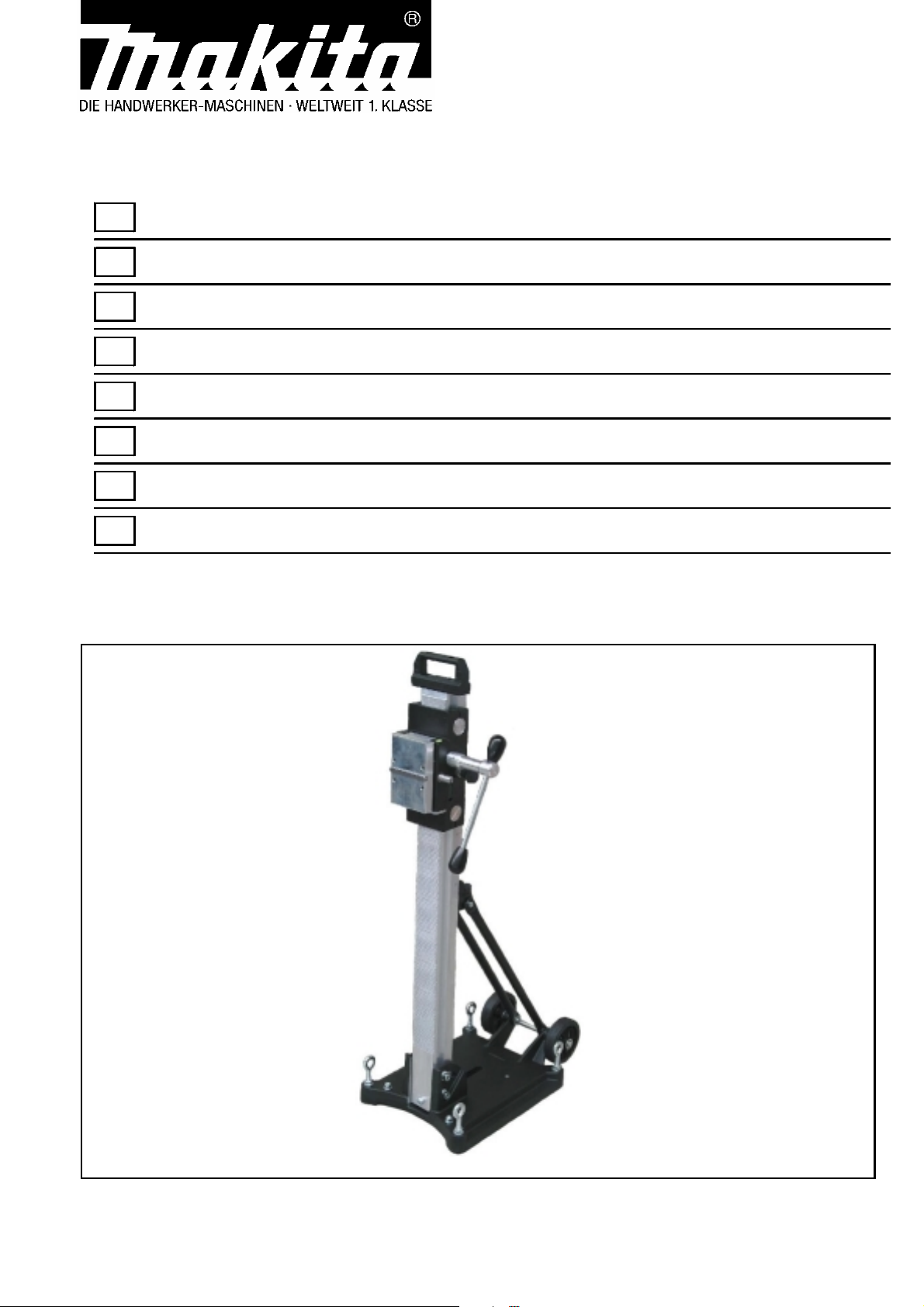
Diamantbohrständer
GB
PT
NL
DK
Diamond drilling stand
F
Support de carrotage
I
Intelaiatura per carotatrice
E
Soporte de taladro a diamante
Suporte de perfuração com diamante
Diamantboor standaard
Diamantborestander
Betriebsanleitung
Operating Instructions
Instruction d’utilisation
Manuale Istruzioni
Manual de Instrucciones
Návod k obsluze
Gebruiksaanwijzing
Betjeningsvejledning
P-54190
Page 2
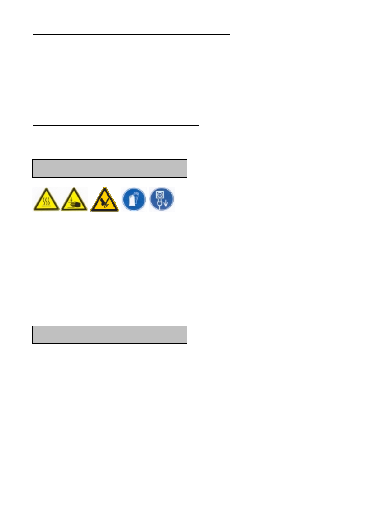
Piktogramme
DEUTSCH
Warnung vor allgemeiner Gefahr
Warnung vor gefährlicher elektrischer Spannung
Warnung vor heißer Oberfläche
Maschine, Bohrkrone und Bohrständer sind schwer –
Vorsicht Quetschgefahr
Reiß- bzw. Schneidgefahr
Zu Ihrem Schutz sollten Sie folgende Schutzmaßnahmen treffen
Gehörschutz benutzen
Augenschutz benutzen
Schutzhelm benutzen
Schutzhandschuhe benutzen
Schutzschuhe benutzen
Vor allen Arbeiten am Gerät unbedingt Netzstecker
ziehen!
1
Page 3

Technische Daten
Diamantbohrständer P-54190
Maße: 520 x 330 x 1100 mm
Säulenlänge: 995 mm
Gewicht: 20,3 kg
Maximaler Bohrdurchmesser: 230
Neigung: 0° bis 45°
Schlittenbremse: Ja
Arretierung in der Endlage: Ja
Aufnahme des Motors: Schnellwechselplatte
Anpassung an Untergrund: 4 Verstellschrauben / 2 Libellen
Lieferumfang
Diamantbohrständer mit Befestigungsschrauben, Innensechskantschlüssel,
Drehkreuz und Bedienungsanleitung im Karton.
Bestimmungsgemäßer Gebrauch
Der Diamantbohrständer P-54190 ist für Diamantkernbohrgeräte mit
Befestigung mittels Montageplatte ausgelegt. Der maximale Bohrdurchmesser
darf 230 mm nicht überschreiten!
Bei Bohrungen nach oben ist generell eine Wasserauffangvorrichtung zu
verwenden.
Bei falschem oder zweckentfremdetem Gebrauch übernimmt der Hersteller
keinerlei Haftung.
2
Page 4
Einsatz
Überprüfen Sie nach jeder Neueinstellung den festen Sitz
der Schrauben, damit sicher mit dem Bohrständer
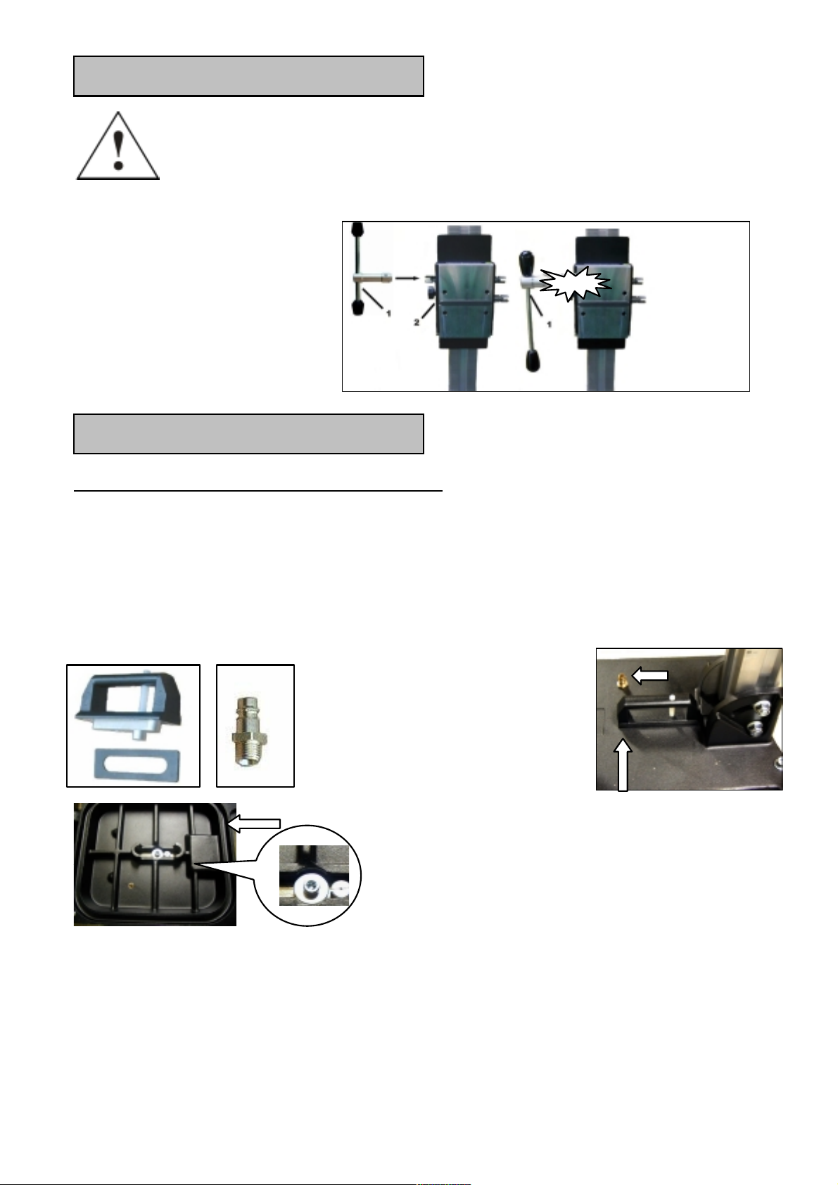
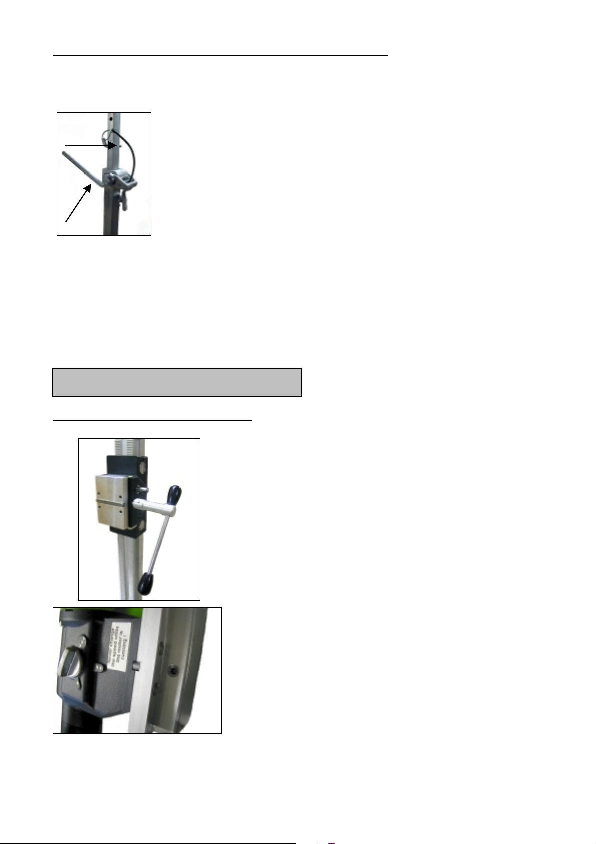
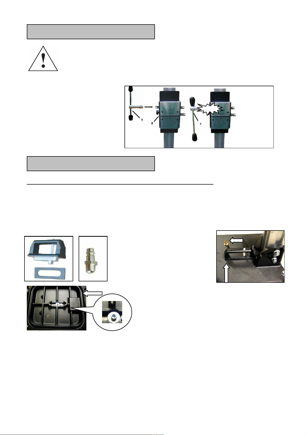
Anbringung des Drehkreuzes
! Bringen Sie das Drehkreuz
(1) in Abhängigkeit von der
auszuführenden Arbeit links
oder rechts am Schlitten (2)
an.
! Prüfen Sie, ob das
Drehkreuz (1) fest sitzt.
Befestigung des Ständers
Befestigung durch Vakuum am Fußboden
Verwenden Sie die Vakuumbefestigung nicht an Wänden oder Überkopf!
Für eine Unterdruck-Anbringung darf die zu bohrende Fläche nicht
porös und muss eben und rissfrei sein.
Ist das nicht der Fall, kann diese Art der Befestigung nicht verwendet werden.
Für die Vakuum-Anbringung benötigen Sie das Vakuumset für P-54190,
Vakuumpumpe und –schlauch. Diese sind auf Anfrage erhältlich.
Verbinden Sie den Bohrständer und die Vakuumpumpe mit Hilfe des
Vakuumschlauchs.
Bringen Sie den Bohrständer in die richtige Position und schalten Sie die Pumpe
ein.
Überprüfen Sie, ob alle vier Nivellierschrauben in der Fußplatte ganz zurück
gearbeitet werden kann.
Klick
Schrauben Sie das
Stecknippel in die Fußplatte.
Dieses ist vorher mit
Dichtband zu versehen.
Setzen Sie den Vakuumgriff
mit der Dichtung ein.
Sichern Sie den Vakuumgriff mit Hilfe
der Unterlegscheibe und
Innensechskantschraube M8x30 und
setzen Sie die Fußdichtung in die
dafür vorgesehene Aussparung ein.
3
Page 5

gedreht sind und ein Unterdruck von mind. –0,8 bar erreicht wird.
Durch drücken des Ventilknopfes im Griff kann der Bohrständer entlastet und
nachjustiert werden.
Die Vakuumpumpe muss während der gesamten Arbeitszeit weiterlaufen
und ist so zu platzieren, dass sie das Manometer Einsehen können.
Überprüfen Sie unbedingt den festen Sitz bevor Sie mit dem Bohren
beginnen!
Befestigung durch Dübel in Beton
Für Mauerwerk sind SpreitzDübel zu verwenden.
! Zeichnen Sie sich die Position der
Befestigungsbohrung auf der zu bohrenden
Fläche an.
! Bohren Sie ein Loch (Ø 15) 50 mm
tief (A), in das der Dübel M12 (B) eingesetzt
werden soll; setzen Sie den Dübel ein und
spreizen Sie ihn mit dem Dübelsetzwerkzeug
(C)auf.
! Schrauben Sie die Schnellspannschraube (D)
in den Dübel ein.
! Setzen Sie den Ständer auf.
! Fixieren Sie die Unterlegscheibe (E)
und schließlich die Befestigungsmutter (F) auf
der Schnellspannschraube (D).
! Ziehen Sie die Mutter (F) mit einem
Schlüssel SW 27 fest.
! Vor und nach dem Festziehen der Mutter (F)
sind die 4 Stellschrauben zur Anpassung an
den Untergrund entsprechend zu verstellen.
Unbedingt prüfen, ob der
Ständer fest montiert ist.
4
Page 6
Befestigung durch Schnellspannsäule
Um den Bohrständer mittels der Schnellspannsäule Verstreben zu können,
muss der Abstand zur gegenüberliegenden Wand zwischen 1,7 m und 3 m
betragen.
H
Positionieren Sie den Bohrständer. Setzen Sie die
Schnellspannsäule so dicht wie möglich hinter der Säule
auf dem Ständerfuß auf. Fixieren Sie den Bohrständer
durch Drehen der Kurbel (G) in Uhrzeigersinn. Sichern Sie
die Einstellung mit dem dazugehörigen Bolzen (H).
G
Achtung! Es ist wichtig, dass der Bohrständer fest mit dem Untergrund
verbunden ist. Nicht korrekt befestigte Bohrständer können zur Verletzung
des Bedieners und Beschädigung der Bohreinheit führen. Bewegungen
während des Bohrens verursachen ein Schlagen der Bohrkrone gegen die
Bohrungswand, was zum Ausbrechen der Segmente führen kann. Die
Bohrkrone kann sich ebenso im Bohrloch verkanten, was wiederum
Schäden an dieser verursacht.
Befestigung der Kernbohrmaschine
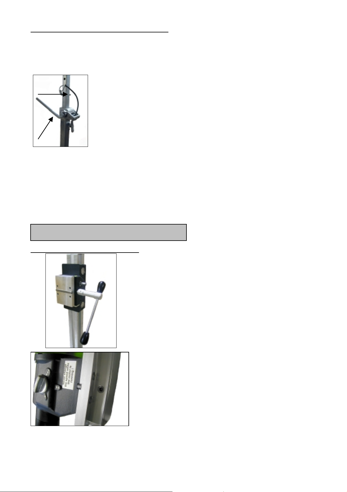
Montage der Maschinenplatte
Fahren Sie den Maschinenhalter mit dem
Kernbohrgerät so weit nach oben, bis dieser in
der Endlage einrastet.
Öffnen Sie mit Hilfe des Drehkreuzes die
Arretierung der Montageplatte.
Entnehmen Sie diese und verbinden Sie sie wie
nachfolgend beschrieben mit der
Kernbohrmaschine.
Zum Lieferumfang gehört eine Montageplatte,
eine Passfeder 10 mm und
4 Innensechskantschrauben M8 x 20. Die
Montageplatte wird mit der Passfeder so auf die
Maschine aufgesetzt, dass sich die Buchse in
der Montageplatte auf der gleichen Seite
befindet wie die Getriebeumschaltung der
Maschine. Danach werden die vier Schrauben
eingesetzt und fest angezogen.
5
Page 7
Setzen Sie die Kernbohrmaschine mit der montierten Platte in den Bohrständer
ein und Arretieren Sie diese mit Hilfe des Drehkreuze (s. Seite 5).
Für den Betrieb der Kernbohrmaschine sind deren Bedienungsanleitung
und die zugehörigen Sicherheitshinweise strikt zu beachten!
Bohrkronenwechsel
Vorsicht!
Das Werkzeug ist schwer und kann durch den Einsatz oder durch
Schärfen heiß werden. Sie können sich die Hände verbrennen, sich an den
Segmenten schneiden bzw. reißen oder quetschen.
Benutzen Sie für den Werkzeugwechsel deshalb immer
Arbeitsschutzhandschuhe.
Vor allen Arbeiten am Gerät
unbedingt Netzstecker ziehen!
Fahren Sie den Maschinenhalter mit dem Kernbohrgerät so weit nach
oben, bis dieser in der Endlage einrastet.
Betrieben
Um die Bohreinheit sicher zu betreiben, beachten Sie bitte folgende Hinweise:
Angaben zum Einsatzort
! Befreien Sie den Einsatzort von allem, was den Arbeitsvorgang
behindern könnte.
! Achten Sie auf ausreichende Beleuchtung des Einsatzortes.
! Halten Sie die angegebenen Bedingungen für den Anschluss an die
Stromversorgung ein.
! Verlegen Sie die Elektroleitungen so, dass eine Beschädigung durch
das Werkzeug ausgeschlossen ist.
! Vergewissern Sie sich, dass Sie ständig ausreichend Sicht auf den
Arbeitsbereich haben und jederzeit alle erforderlichen
Bedienungselemente und Sicherheitseinrichtungen erreichen können.
! Halten Sie andere Personen von Ihrem Arbeitsbereich fern, um Unfälle
zu vermeiden.
Raumbedarf für Betrieb und Wartung
Halten Sie wenn möglich ca. 2 m um die Maschine für Betrieb und Wartung frei,
so dass Sie sicher arbeiten können und bei Betriebsstörungen sofort
eingegriffen werden kann.
6
Page 8

Bohren
Vorbereitung
! Wenn Sie in Blöcke bohren, stellen Sie sicher, dass die Blöcke gut
verankert und befestigt sind.
! Bevor Sie in tragende Teile bohren, vergewissern Sie sich, dass Sie die
Statik nicht verletzen. Befolgen Sie die Anweisungen der für die
Planung verantwortlichen Fachleute.
! Stellen Sie sicher, dass Sie weder Gas- bzw. Wasserleitungen, noch
Stromkabel beim Bohren beschädigen können.
! Vergewissern Sie sich, dass Sie keine Metallteile der Maschine
während des Bohrens von Wänden und Böden, wo Stromkabel unter
Wasser liegen könnten, berühren.
! Stellen Sie sicher, dass der Bohrkern beim Herausfallen niemanden
verletzen bzw. nichts beschädigen kann. Beräumen und sichern Sie den
Arbeitsbereich.
! Sichern Sie bei Durchgangsbohrungen durch die Decken den Bereich
von unten ab, da der Bohrkern nach unten herausfallen kann.
! Falls der Bohrkern beim Herausfallen Schäden verursachen könnte,
bauen Sie eine entsprechende Vorrichtung auf, die den Kern zurück
hält.
! Vergewissern Sie sich, dass die Bohrkrone richtig befestigt ist.
! Setzen Sie in Abhängigkeit vom zu bearbeitenden Material das richtige
Werkzeug ein.
Ausführung der Bohrarbeiten
! Prüfen Sie Ihre Fehlerstromvorrichtung auf korrekte Funktion.
! Öffnen Sie die Wasserzuführung.
! Schalten Sie den Motor ein, ohne dass die Bohrkrone die Fläche
berührt.
! Senken Sie die Bohrkrone soweit ab, bis sie die Oberfläche berührt.
! Um eine exakte Zentrierung der Bohrkrone zu erhalten, halten Sie beim
ersten Zentimeter Schnitttiefe den Vorschub gering.
!
Sie können nun schneller bohren. Eine zu niedrige Drehzahl der
Maschine schränkt die Leistung ein. Bei einer zu hohen Drehzahl
werden die Diamantsegmente schnell stumpf.
7
Page 9
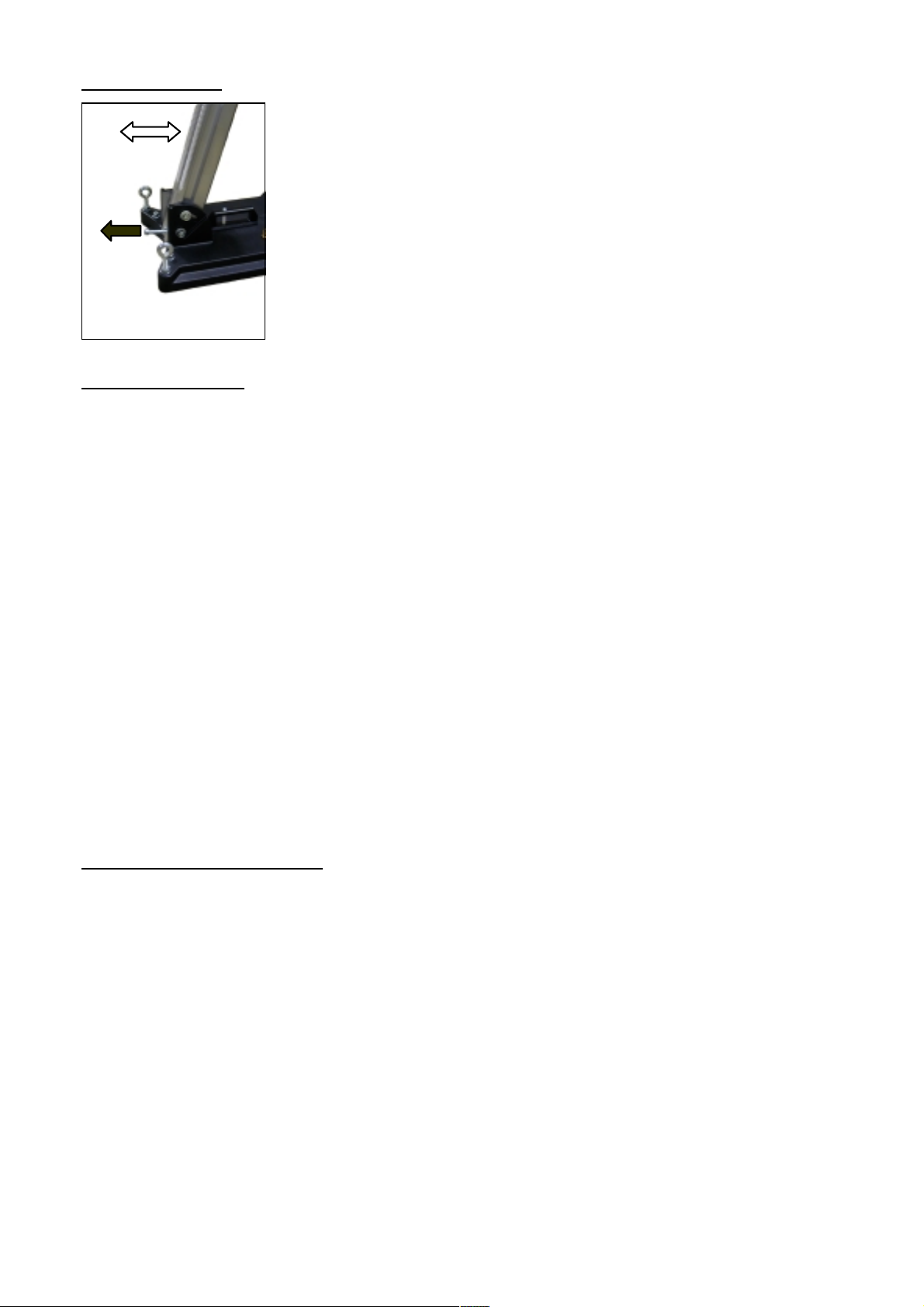
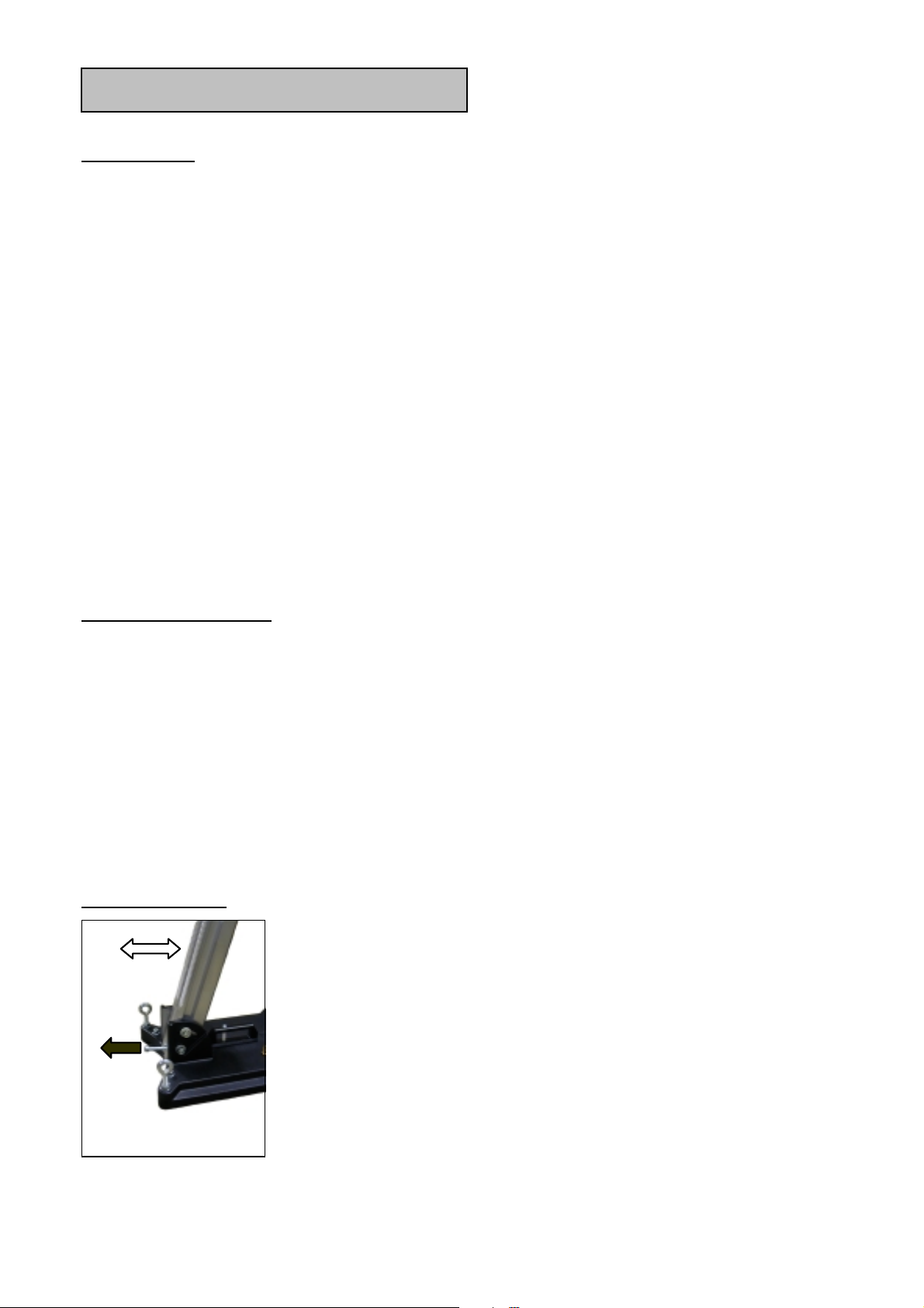
schräg bohren
! Entfernen Sie die Schraube in der Fußplatte, welche
die Säule bei 90° arretiert.
! Lockern Sie die Knebelschraube zwischen
Abstützung und Säule und schwenken Sie die Säule
bis zum gewünschten Winkel.
! Ziehen Sie die Schraube wieder fest.
Bohren Sie am Anfang sehr langsam, da die Krone nur mit
einem Bruchteil ihrer Schnittfläche ins Material greift. Wenn
Sie zu schnell oder mit einem zu hohen Druck bohren kann
die Krone verlaufen.
Überkopf bohren
! Montieren Sie unbedingt eine Wasserabsaugvorrichtung.
! Schließen Sie einen Nasssauger an die Absaugung an und schalten Sie
diesen ein.
! Öffnen Sie die Wasserzuführung und stellen Sie sicher, das das Wasser
die Segmente erreicht hat bevor Sie mit dem Bohren beginnen.
Achten Sie beim Überkopf bohren besonders darauf das kein Wasser in die
Maschine eindringt.
Wenn Sie während des Bohrvorganges feststellen, dass die Vorschubgeschwindigkeit sehr gering wird, dass Sie mehr Kraft aufwenden müssen und
dass das Wasser, das aus dem Bohrloch austritt, klar und mit einigen
Metallsplittern versetzt ist, sind Sie auf Armierungseisen getroffen.
Reduzieren Sie den Druck auf die Bohrkrone und schalten Sie wenn möglich in
den nächst niedrigeren Gang um dieses problemlos zu durchtrennen.
Sie können den Druck bzw. die Drehzahl wieder erhöhen, wenn Sie die
Armierungseisen durchtrennt haben.
Bohrkronenverlängerung
Wenn Sie tiefer als die Nutzlänge Ihrer Bohrkrone bohren müssen:
! Bohren Sie zunächst nur so weit, wie die Nutzlänge der Krone es
zulässt.
! Entfernen Sie die Krone und lösen den Bohrkern aus dem Loch, ohne
die Kernbohranlage zu bewegen.
! Schieben Sie die Krone wieder ins Bohrloch.
Schrauben Sie eine entsprechende Verlängerung zwischen Bohrkrone und
Motor. Wenn die Bohrkronenaufnahme 1¼‘‘ beträgt, vergessen Sie bitte nicht
die Kupferringe zum leichteren Lösen der Bohrkrone.
8
Page 10
Segmentbruch
Wenn sich während des Bohrens ein Diamantsegment, Teile der Armierung
oder ähnliches lösen und die Bohrkrone dadurch verklemmt, beenden Sie die
Arbeit an dieser Bohrung und bohren Sie ein Loch mit dem selben Zentrum und
einem 15 bis 20 mm größeren Durchmesser.
Versuchen Sie nicht mit einer anderen Bohrkrone gleichen Durchmessers
die Bohrung zu beenden!
Nach dem Bohren
Wenn Sie Ihre Bohrung beendet haben:
! Ziehen Sie die Bohrkrone aus dem Loch heraus.
! Schalten Sie die Maschine aus.
! Schließen Sie die Wasserversorgung.
Bohrkern entfernen, wenn er in der Bohrkrone bleibt
! Trennen Sie die Bohrkrone vom Motor.
! Stellen Sie die Bohrkrone senkrecht.
! Klopfen Sie leicht mit einem hölzernen Hammerstiel gegen das Rohr,
bis der Bohrkern herausrutscht. Die Bohrkrone nie mit Gewalt gegen
eine Wand schlagen, oder mit Werkzeugen wie Hämmern oder
Maulschlüsseln traktieren, da sich das Rohr sonst verziehen kann und
weder der Bohrkern sich herauslösen, noch die Bohrkrone sich
wiederverwenden lässt.
Bohrkern entfernen bei einem Sackloch
Brechen Sie den Kern mit einem Keil oder Hebel ab. Heben Sie den Kern mit
einer geeigneten Zange heraus oder bohren Sie ein Loch in den Kern,
schrauben eine Ringschraube hinein und ziehen Sie ihn daran heraus.
Demontage der Kernbohreinheit
! Fahren Sie den Maschinenhalter mit dem Kernbohrgerät so weit nach
oben, bis dieser in der Endlage einrastet.
! Entfernen Sie die Bohrkrone.
9
Page 11
! Lösen die Arretierung der Montageplatte und heben Sie die
Kernbohrmaschine aus der Bohrständer. ( s.S. 5)
! Lösen Sie die Flügelmutter (F). (s.S. 4)
Halten Sie dabei den Bohrständer fest!
! Entnehmen Sie den Bohrständer.
! Drehen Sie die Schnellspannschraube (D) heraus. (s.S. 4)
Lärmentwicklung
Der Schalldruckpegel am Arbeitsplatz kann 85 dB (A) überschreiten; in diesem
Fall sind Schallschutzmaßnahmen für den Bediener erforderlich.
Gehörschutz tragen!
Pflege und Wartung
! Halten Sie den Ständer immer sauber, insbesondere die Bohrsäule mit
der Verzahnung und den 4 Gleitstücken im Maschinenhalter .
Um die Leichtgängigkeit der Ritzelwelle zu gewährleisten ist diese
etwas zu ölen.
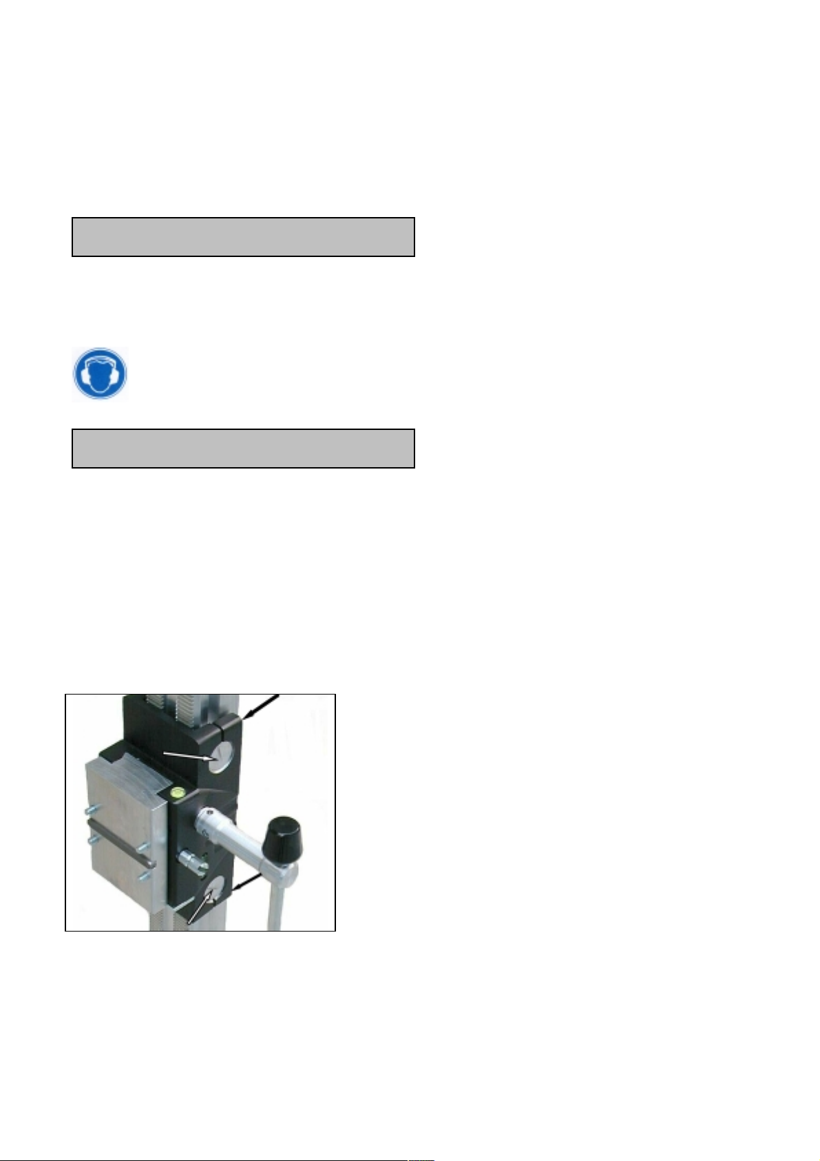
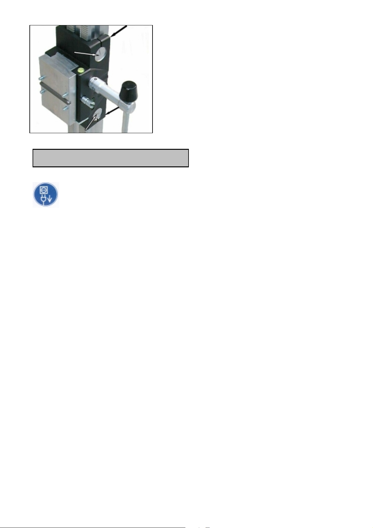
! Für den einwandfreien Betrieb des Bohrständers müssen die
Gleitstücke des Maschinenhalters spielfrei an der Bohrsäule entlang
gleiten.
Sollte sich die Position verändert haben, kann sie wie folgt nachgestellt
werden:
! Lösen Sie mit Hilfe eines
Innensechskantschlüssels SW 5 die
beiden Innensechskantschrauben.
! Regulieren Sie mit Hilfe eines
Schraubendrehers die beiden
Verstellschrauben.
Ziehen Sie die Innensechskantschrauben
wieder fest und prüfen Sie die
Leichtgängigkeit des Diamantbohrständers.
10
Page 12

Verhalten bei Störungen
Schalten Sie die Maschine bei Betriebsstörungen aus und
trennen Sie diese vom Stromnetz. Arbeiten an der Elektrik der
Maschine dürfen nur von einem Elektrofachmann vorgenommen
werden.
11
Page 13
ENGLISH
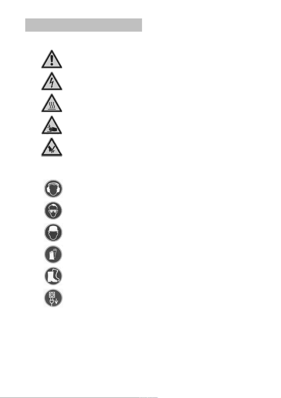
Icons
Warning: general precaution
Warning: dangerous voltage
Warning: hot surface
Tool, drill bit and stand are heavyCaution: risk of squashing
Danger of tearing or cutting
For your protection the following safety measures must be taken:
Wear ear protection
Wear safety goggles
Wear protective helmet
Wear protective gloves
Wear safety shoes
!
Do disconnect from power before working on the tool!
12
Page 14

Technical data
Diamond drilling stand P-54190
Measures: 520 x 330 x 1100 mm
Length of support: 995 mm
Weight: 20,3 kg
Max. drilling diameter: 230 mm
Inclination: 0° to 45°
Carriage brake: yes
Locking in final position: yes
Fixture of the motor: quick lock plate
Adaption to surface: 4 positioning screws/ 2 fair levels
Delivery volume
Diamond drilling stand with mounting screws, Hexagon wrench,
turnstile and operating instructions in a carton.
Prescribed use
The diamond drilling stand P-54190 is designed for diamond core drills which
are fixed by means of a mounting plate. The max. drilling diameter must not
exceed 230 mm.
When drilling overhead, a water collecting device must be used.
The manufacturer’s liability does not cover cases of incorrect handling
or misuse.
13
Page 15

Operations
Check after each readjustment that the screws are tightly
fixed so that safe operating of the drilling stand is possible.
Mounting of the turnstile
! Mount the turnstile (1) on the right
or left side of the carriage (2) depending on the kind of work to be performed.
! Check whether the turnstile (1) is
fixed tightly.
Mounting of the stand
Fixing the mount on the floor by vacuum
Do not use vacuum fixing on walls or overhead. Vacuum fixing may only be
used if the area to be drilled is level, free of pinholes and cracks, otherwise this
method cannot be applied. For the vacuum fixing you need the vacuum set P54190, vacuum pump and –hose. They are available on request.
Screw the plug-in nipple into
the foot plate, to which previously a seal strip has been
applied. Insert the vacuum
handle with the seal.
Click
Fasten the vacuum handle with a
washer and hexagon hollow head plug
M8x30 and insert the foot sealing into
the corresponding notch.
Connect the drilling stand and the vacuum pump by means of the vacuum hose.
Bring the drilling stand into the correct position and switch the pump on.
Check whether the four levelling screws are completely turned back and a vacuum of min. -0.8 bar is achieved.
14
Page 16

By pressing the valve button on the handle the drilling stand may be disengaged
and readjusted.
The vacuum pump has to run during the complete operation, it is to be
placed in such a position that you can monitor the pressure gauge at all
times.
It is mandatory to check that the foot plate is firmly affixed to the surface
before drilling is started.
Fixing by means of dowels in concrete
For brickwork, anchor must be used.
! Mark the position of the drill holes for the fixing
on the surface to be drilled.
! Drill a hole (Ø 15) 50 mm deep (A), into which
the dowel M 12 (B) is to be placed; insert and
secure the dowel with the doweling tool (C).
! Screw the quick action clamping screw (D) into
the dowel.
! Install the stand.
! Fix the washer (E) and finally the fastening nut
(F) on the quick action clamping screw (D).
! Torque the fastening nut with a 27mm wrench.
! Before and after tightening the nut (F), the four
adjustable screws have to be adjusted in order
to adapt the stand to the surface.
Do check whether the stand is installed
safely and firmly.
15
Page 17
Fixing by means of the quick release fastener support
In order to brace the drill stand by means of the quick release fastener
support, the distance to the opposite wall must be between 1.7 and 3 m.
H
Position the drilling stand. Position the quick release fastener support as close as possible behind the support on
the base of the stand. Fix the stand by turning crank (G)
clockwise. Secure in position by means of the appropriate
bolt (H).
G
Warning! It is important that the drilling stand is firmly connected to the
surface. If not fixed correctly, injuries to the operator or damages to the
drilling unit may be the caused. Uncontrolled movements during drilling
will cause the drill bit to hit the surface to be drilled, which may lead to a
chipping of the segments. The drill bit might also tilt in the bore hole
which consequently will damage it.
Fixing the core drill tool
Setting up of the mounting plate
Move the tool mount with the attached core drill
tool upwards until it locks in the final position.
Use the turnstile to open the locking device of
the mounting plate. Remove it and connect it to
the core drill tool as described subsequently.
The tool is supplied with a mounting plate, a 10
mm fitting key and 4 hexagon hollow head plugs
M8x20. The mounting plate is attached to the
tool with the fitting key so that the coupling on
the mounting plate is on the same side as the
gear change of the engine. Then the 4 plugs are
inserted and torqued tightly.
16
Page 18
Insert the core drill tool with the attached mounting plate into the drilling stand
and lock it with the turnstile (see page16).
For the operation of the core drill tool, the operationing instructions and
the safety rules have to be strictly observed!
Changing the drill bit
Warning!
The tool is heavy and may heat up during operation or during sharpening.
You could burn, cut, tear or squash your hands on the segments.
Therefore always wear protective gloves when changing tools.
Before working on the equipment pull the power plug from the socket!
Move the tool mount with the attached core drill tool upwards until it locks
in the final position.
Operations
In order to operate the tool safely, please observe the following notes:
Details of the work area
! Keep the work area free of everything which could obstruct operations.
! Provide for adequate illumination of the work area.
! Adhere to the regulations concerning the power connection.
! Lay the power cable in such a way that any damage by the drill can be
avoided.
! Make sure to always keep the work area in view and to be able to reach
all necessary operating elements and safety installations.
! Keep other persons away from your work area in order to avoid acci-
dents.
Space requirements for operating and maintenance
Whenever possible, keep a free space for operating and maintenance of about 2
m around the drill position, so that you can work safely and have immediate
access in case of a malfunction.
17
Page 19
Drilling
Preparation
! When drilling into blocks make sure that they are well fixed and fas-
tened.
! Before drilling into load bearing elements make sure that the founda-
tions are not damaged. Follow the instructions of the specialists responsible for planning.
! Make sure not to damage any water or gas pipes or power lines during
drilling.
! Make sure not to touch any metal parts of the tool when drilling in walls
or floors, where power lines might be lying in water.
! Make sure that the drill core will not hurt anybody or cause damage to
anything when falling out. Clear and secure the work area.
! When drilling through holes through ceilings, secure the area from be-
low, as the drill core may drop downwards.
! If the drill core could cause damage when dropping down, set up a cor-
doned off area.
! Make sure that the drill bit is fixed correctly.
! Use the correct tools appropriate for the material to be worked upon.
Execution of drilling
!
Check PRCD for correct function.
!
Open the water supply.
!
Switch the motor to ON, the drill bit must not yet touch the surface.
!
Lower the drill bit until it touches the surface.
In order to achieve an exact centering of the drill bit, minimize the for-
!
ward travel of the drill bit during the first centimetre of cutting depth.
!
Now you may increase the drilling speed. If the speed is too low, the
performance of the tool is impaired. If the speed is too high, the diamond segments will become blunt in a short time.
Inclined drilling
! Remove the bolt, which holds the support at a 90° an-
gle, from the foot plate.
! Loosen the thumb screw between base and support
and swivel the support to the desired angle.
! Tighten the screw again.
At the beginning, drill at a low speed, as the drill bit enters into
the material with only a part of its cutting edge. If the drill
speed or pressure is too high, the drill bit may become erratic.
18
Page 20

Overhead drilling
! You must install a water extracting device.
! Connect a wet vacuum cleaner to the extracting device and switch it on.
! Open the water supply and make sure that the water reaches the seg-
ments before you start drilling.
When drilling overhead take special care that no water gets into the tool. In case
you notice during drilling, that the advance speed decreases considerably, that
you have to increase pressure and that the water emerging out of the bore hole
is clear and mixed with metal splinters, you have probably hit reinforcement iron.
Reduce the pressure on the drill bit and switch to the next lower gear if possible
so that you may cut through the reinforcement without problems.
Once it is cut through, you may increase pressure and speed.
Extension of the drill bit
In case you have to drill deeper than the working length of the drill bit permits:
! At the outset, drill only as deep as the working length permits.
! Remove the drill bit and take the drill core out of the drilled hole without
moving the core drilling installation.
! Put the drill bit back into the drilled hole.
Install an appropriate extension between drill bit and motor. If the drill bit holding
fixture is 1¼ “ do not forget the copper rings to facilitate the loosening of the drill
bit.
Breaking of a segment
In case that a diamond segment, parts of the reinforcement or similar loosens
during drilling and the drill bit thereby gets jammed, stop working on this bore
hole and drill a hole with the same centre and a 15 to 20 mm greater diameter.
Do not try to finish drilling with a different bit of the same diameter!
After drilling
After you have finished drilling:
! Pull the drill bit out of the bore hole.
! Switch the motor off.
! Close the water supply.
19
Page 21
Removal of the bore core when stuck in the drill bit
! Separate the drill bit from the motor.
! Put the drill bit in a vertical position.
! With the wooden handle of a hammer, slightly tap against the tube until
the core drops out. Never knock the drill bit forcefully against a wall or
treat it with tools like hammer or wrench, the tube may become deformed so that neither the bore core will fall out nor the drill bit may be
used again.
Removal of the bore core from a blind hole
Break off the core with a wedge or a lever. Remove the core with suitable pliers
or drill a hole into the core, insert a lifting screw and pull the core out.
Dismounting the core drill unit
! Move the machine holder with the core drill upwards until it locks in the
final position.
! Remove the drill bit.
! Loosen the fixture of the mounting plate and lift the core drill tool out of
the drilling stand (see page 16).
! Loosen the thumb nut (F) (see page 15).
While doing so, hold the drilling stand firmly.
! Remove the drilling stand.
! Loosen the quick action clamping screw (D) (see page 15).
Maintenance and care
! Always keep the drilling stand clean, especially the drill support with the
gear and the 4 sliding pieces in the holder of the machine. In order to
allow the free movement of the pinion shaft it should be slightly lubricated.
! The sliding pieces must move along the drill support without slackness
in order to achieve a good performance.
If the position should have changed, it can be readjusted as follows:
20
Page 22
! Using a 5mm Hexagon wrench,
loosen both Allen screws.
! Adjust the two positioning screws with
a screwdriver.
Tighten the Hexagon screws again and check
whether the diamond drill stand moves
smoothly.
In case of malfunctions
Switch the motor off and disconnect it from the power. Repair of
the electrical parts may only be performed by an authorized service specialist.
21
Page 23
22
Icons
Attention : Règles de sécurité
Attention : Voltage dangereux
Attention : Surface chaude
L’outil, la couronne et le support sont lourds
Attention : Risque d’écrasement
Danger de déchirure ou de coupure
Pour votre protection quelques mesures de sécurité doivent être prises:
Protecteur anti-bruit
Lunettes de protection
Casque
Gants de protection
Chaussures de sécurité
Débrancher la prise de courant avant de travailler sur
L’outil
FRANÇAIS
Page 24

23
Support de carrotage P-54190
Dimensions:
520 x 330 x 1100 mm
Longueur du support:
995 mm
Poids:
20,3 kg
Diamètre de perçage maximum:
230
Inclinaison:
0° to 45°
Frein de manette:
oui
Blocage en position finale:
oui
Fixation du moteur:
Fixation rapide par plaque
Adaption to surface:
4 vis de positionnement/ 2
niveaux
Le support de carottage est livré avec les vis de montage, Clé hexagonale,
Manette, manuel d’instruction dans la boite de livraison.
Le support de carottage P-54190 est conçu pour des carotteuses ayant une
plaque de fixation. Le diamètre maximum de perçage ne peut pas excéder
230mm.
Quand vous percez au dessus de votre tête, utilisez un récupérateur d’eau.
La responsabilité du fabriquant n’est pas engagée dans le cas d’une
mauvaise utilisation.
Caractéristiques techniques
Conditionnement
Utilisation prescrite
Page 25
24
Vérifier après chaque utilisation que les vis soient fixées
correctement pour une utilisation en toute sécurité.
Montage de la manette
- Monter la manette (1) du
coté gauche ou du coté droit
en fonction de l’utilisateur.
- Vérifier que la manette
(2)soit fixée correctement.
Fixation de la base sur le sol au moyen de la pompe à vide
Ne pas utiliser de pompe à vide sur un mur ou au plafond.
La pompe à vide ne peut pas être utilisée si la surface n’est pas plane, si il y a
des craquelures.
Pour la pompe à vide, la référence est P-54190. C’est un accessoire en option.
Vissez l’adaptateur sur la
plaque qui doit être mis avec
un joint d’étanchéité. Puis
adapter la poignée de la
ventouse avec le joint.
Fixer la poignée de l’aspirateur avec une
rondelle et une vis tête hexagonale M8x30
et insérer le joint dans l’encoche
correspondante .
Connecter le support et la pompe au moyen de la connexion.
Positionner correctement la base puis démarrer la pompe.
Vérifier que les quatre vis de réglage de niveau soit complètement dévisser et
que la ventouse soit sous pression atteint -0.8 Bar. En pressant sur la valve de
la poignée la base peut se désengager et peut être réajustée.
Montage du support
Operations
Click
Page 26

25
La pompe à vide doit fonctionner pendant l’opération, elle doit être
positionnée de telle façon de voir sans problèmes la jauge de pression.
Il est fortement recommandé de vérifier la fixation de la base avant de
commencer à percer.
Fixé le base au moyen de cheville
Pour de la brique, utilisez des chevilles
rétractables.
Indiquez les positions des trous qui doivent
être percé.
Perçer un trou (Ø 15) 50mm de profondeur (A)
dans lequel une cheville M12(B) sera placée
au moyen de l’outil (C).
Insérer la tige filetée (D) dans la cheville.
Installer la base.
Placer la rondelle (E) et puis l’écrou
spécial(F) sur la tige filetée (D).
Serrer l’écrou spécial au moyen d’une clé
(SW27).
Avant de serrer l’écrou, régler la tige filetée.
Vous devez vérifier si la base est
solidement arrimée.
Page 27

26
Fixer la base avec l’étau
Pour pouvoir employer l’étau à rallonge, la distance entre les murs doit
être de 1.7m à 3m.
Positionner l’ensemble. Positionner l’étau à rallonge le
plus près de la base. Fixer en tournant la manivelle(G)
dans le sens des aiguilles d’une montre.Sécuriser
l’ensemble avec l’écrou approprié(H).
Attention : Le support doit être en contact avec la surface. Si cela n’était
pas le cas, l’utilisateur pourrait subir des blessures.
Montage de la machine
Déplacez l’outil à l’aide de la manivelle et serrer
en position finale.
Utiliser la manivelle pour déverrouiller la plaque
de maintien; Prener la et fixer la sur la
carotteuse comme décrit ci-dessous.
Le support de carotteuse P-54190 est livré avec
une plaque de maintien, une clé plate de 10mm
et 4 vis M8. La plaque de maintien se fixe sur
l’outil à l’aide la clé de telle manière à ce que
l’accouplement soit du même coté que du
sélecteur de vitesse.Puis visser les 4 vis.
Insérer la carotteuse avec la plaque de montage dans le support et fixer avec la
manivelle( voir ci-dessus).
Pour les opérations de carottage, les instructions et les règles de sécurité
doivent être respectées.
Fixation de la carotteuse
Page 28

27
Attention!
Cet outil est lourd et peut chauffer pendant son utilisation. Vous pouvez
vous bruler les mains, vous coupez, vous égratignez avec les segments.
Débrancher la prise de courant avant d’intervenir sur la machine. Attendez
que la machine soit complètement arrêtée.
Portez toujours des gants pour changer l’accessoire.
Pour utiliser cette machine en toute sécurité, vous devez observer les règles
suivantes:
Environnement du lieu de travail
Gardez votre lieu de travail propre.
Le lieu de travail doit être suffisamment éclairé.
Se conformer à la réglementations en ce qui concerne le cable
électrique.
L’alimentation électrique ne doit pas être endommagé par l’outil.
Faites en sorte de pouvoir atteindre sans problèmes tous les points
nécessaires à la sécurité.
Maintenez toutes personnes à distance pour éviter les accidents.
Espace nécessaire pour une utilisation en toute sécurité.
Maintenez votre endroit de travail sans encombrement (2m).
Préparation
Vérifier que les blocs à percer soient solidement fixés.
Avant de percer, vérifier de ne pas entrer en contact avec une conduite
de gaz, d’eau ou d’électricité.
Soyez sur que lorsque la carotte aura traverse la partie à percer que
personne soit blessée.
Faites attention de ne pas percer de pièces en fer dans un mur ou
plancher, vous pouvez éventuellement provoquer des accidents avec
l’eau.
C’est la même chose pour le perçage d’un plafond.
Perçage
Changement d’accessoire
Préparation
Page 29

28
Si il y a une possibilité que l’appareil tombe, prévoyez un système de
retenu.
Vérifiez que la carotte soit fixée correctement.
Utilisez rune carotte en fonction de la matière à percer.
Vérifiez que le support soit fixé fermement au sol.
Phase de perçage
Vérifier le parfait fonctionnement du disjoncteur de surcharge avant
utilisation.
Open the water supply.
Ouvrir le robinet d’eau.
Mettre la carotteuse en marche, toutefois la couronne ne doit pas
encore touchée la surface à percer.
Mettre en contact la surface à percer avec la couronne.
Enfin, pour effectuer un centrage parfait, éviter de forcer pendant le
premier centimètre de perçage.
Maintenant, vous pouvez accélérer si la vitesse est trop élevée, les
segments de la couronne deviendront vite émoussés.
Perçage incliné
Enlever l’écrou de la plaque, qui maintient la colonne
à 90°
Desserrer la vis entre le support et la colonne et
choississez l’angle désiré.
Serrer à nouveau les deux boulons.
Au commencement du perçage, utilisé une vitesse
lenteau débute du perçage. Si la vitesse est
excessive ou la pression trop importante le perçage
peut être irrégulier.
Perçage en l’air
Vous devez installer un récupérateur d’eau.
Connectez l’aspirateur d’eau au collecteur et mettez le en marche.
Ouvrir le robinet d’eau et assurez vous que l’eau atteint les segments
de la couronne avant de démarrer le perçage.
Quand vous percer en l’air faites attention à ce que l’eau n’entre pas
dans la machine.
Dans le cas ou vous remarquer que durant le perçage la vitesse se réduit, et
que vous êtes obligé d’accentuer la pression et que l’eau qui sort est mélangée
avec de la limaille de fer, vous êtes certainement en contact avec un morceau
de ferraille.
Page 30

29
Rallonge de trépan
Si vous avez à faire un trou plus profond que le matériel dont vous disposez:
Dans un premier temps, faites le trou avec le matériel dont vous
disposez.
Enlever le trépan et le porte-trépan du trou sans démonter l’installation.
Repositionner l’ensemble dans le trou.
Mettre une rallonge appropriée. Il est préférable de mettre une rondelle de
bronze pour faciliter le démontage.
Dans le cas ou un segment casse ou un autre morceau de fer empêche de
percer, arrêtez immédiatement le perçage. Faire un trou avec un autre
accessoire avec un diamètre de 15mm ou 20mm supérieure.
N’essayez jamais de repercer avec un accessoire de même diamètre.
Après avoir fini de percer:
Enlever l’outil du trou.
Pour arrêter le moteur. Utiliser l’interrupteur et non le disjonteur de
sécurité.
Fermer le robinet.
Enlever le morceau de carrotte lorsqu’il est est bloqué à l’intérieur de
l’accessoire
Démonter l’accessoire de l’outil.
Mettez l’accessoire en position droite.
Taper tout doucement avec un morceau de bois contre le tube afin de
faire tomber le morceau de carotte.Ne jamais utiliser de marteau ou
d’un outil dur pour effectuer cette opération. Car vous ne pourriez pas
réutiliser l’accesssoire.
Enlever la carotte d’un trou aveugle
Casser la carotte à l’aide d’un levier et puis enlever la carotte avec un tournevis.
Après le perçage
Segment cassé
Page 31

30
Entretien et suivi
Remonter l’ensemble du système et bloquer en position haute.
Démonter la carotte.
Desserer la plaque de fixation et enlever la carotteuse du support( Voir
page 26).
Desserer l’écrou (F) (voir page 25).
Maintenez fermement le support en faisant cette opération.
Démonter le support.
Dévisser la vis à serrage rapide (D) (voir page 25).
Essayer de garder le support propre, spécialement l’engrenage et les 4
pièces qui coulissent. l’ensemble doit être lubrifié régulièrement pour un
bon fonctionnement.
Les pièces doivent se déplacer sans à coups pour avoir de bonnes
performances.
ISi il y a des difficultés de déplacement procéder aux modifications
comme ci-dessous indiquées:
Dans le cas d’un mauvais fonctionnement de l’interrupteur, il faut
débrancher l’outil. Les réparations des outils électriques ne
peuvent se faire seulement par spécialiste agréé.
Utiliser une clé Allen pour désserer
les vis à tête hexagonale.
Ajuster les deux vis de ositionnement
avec un tournevis.
Serer encore les vis et vérifier si la tête se
déplace sans effort.
Démontage du trépan
Fonctionnement défectueux
Page 32

ITALIANO
Simboli
Attenzione: Precauzioni generali
Attenzione: Passaggio di corrente
Attenzione: Superficie calda
Utilizzare l’utensile con cautela: Pericolo di schiacciamento
Pericolo di lacerazioni e tagli
Per la Vostra sicurezza adottare le seguenti misure:
Indossare cuffie insonorizzatrici
Indossare occhiali protettivi
Indossare un casco protettivo
Indossare guanti protettivi
Indossare scarpe antinfortunistiche
Scollegare l’utensile dalla rete elettrica, prima di effettuare della manutenzione su di esso
31
Page 33

Dati Tecnici
Intelaiatura per carotatrice: cod. P-54190
Quote dimensionali: 520 x 330 x 1100 mm
Lunghezza del supporto: 995 mm
Peso: 20,3 kg
Ø MAX di foratura: 230 mm
Inclinazione: Da 0° a 45°
Freno carrello: SI
Sistema di bloccaggio: SI
Fissaggio del motore: Piastra con bloccaggio rapido
Livellamento: 4 viti di posizionamento / 2 Livelle
Imballaggio
Intelaiatura completa di viti, chiave esagonale, leva e manuale istruzioni inserite
in una scatola di cartone.
Specifiche di utilizzo
L’intelaiatura P-54190 è studiata per essere utilizzata con una carotatrice fissata
tramite l’apposita piastra di montaggio. Il Ø MAX di foratura non deve essere
maggiore di 230mm.
Quando si fora a soffitto si deve utilizzare il dispositivo di estrazione acqua.
Il produttore declina qualsiasi responsabilità in caso di trasporto o utilizzo
non conforme.
32
Page 34

Operazioni
Controllare sempre, dopo ogni regolazione, che le viti siano
serrate saldamente in modo da poter operare in completa
sicurezza.
Montaggio della leva
! Inserire la leva (1) nella relativa
sede del carrello (2), sul lato destro
(o sinistro), in base al tipo di posizionamento.
! Accertarsi che la leva (1) sia fissata
correttamente.
Click
Montaggio Intelaiatura
Fissaggio del supporto su pavimento tramite depressione
Non utilizzare il sistema di fissaggio a depressione su pareti o soffitto!
Il sistema di fissaggio a depressione deve essere utilizzato solamente se la
zona di foratura è perfettamente livellata e priva di fori e crepe; altrimenti questo
metodo non deve essere assolutamente utilizzato. Per utilizzare il sistema di
fissaggio a depressione, si deve richiedere l’apposito kit (Pompa a vuoto, tubazioni) da applicare all’intelaiatura P-54190.
Applicare sulla base la relativa guarnizione, quindi avvitare il nipplo. Posizionare la
maniglia e la guarnizione.
Fissare la maniglia a depressione con
la rondella ed il dado M8x30, quindi
inserire la base sigillata nella sede
corrispondente.
Collegare la pompa a vuoto all’intelaiatura, mediante l’apposito tubo.
Disporre il supporto nella posizione di lavoro ed avviare la pompa a vuoto.
33
Page 35

Verificare che tutte le 4 viti di livellamento siano completamente ruotate e che ci
sia una depressione di almeno -0,8 bar.
Premendo il pulsante della valvola di scarico, posto sulla maniglia, è possibile
liberare e rimuovere il supporto.
La pompa a vuoto deve essere sempre in funzione per tutta la durata della
lavorazione, deve essere posizionata in modo da poter vedere sempre il
livello della pressione.
E’ essenziale controllare che la base sia saldamente fissata prima di iniziare la foratura.
Fissaggio del supporto su cemento, tramite perni di riferimento
Su muratura in mattoni è necessario utilizzare tasselli ad
espansione.
! Segnare sulla superficie il punto in cui si
dovranno eseguire i fori di fissaggio.
! Eseguire un foro di Ø 15mm e profondo
50mm (A), dove verrà poi posizionato il
perno M12 (B); inserire il perno e divaricarlo con l’apposito attrezzo (C).
! Inserire la vite rapida (D) nel perno M12.
! Posizionare il supporto.
! Calettare la rondella (E) e serrare il dado di
fissaggio (F) sulla vite rapida (D).
! Per il serraggio del dado di fissaggio, utiliz-
zare una chiave 27.
! Prima e dopo il serraggio del dado di fis-
saggio (F) le viti di regolazione devono essere regolate.
Controllare scrupolosamente se il supporto
è fissato saldamente ed in sicurezza.
34
Page 36

Fissaggio del supporto tramite sistema di bloccaggio
Allo scopo di sostenere il supporto con il sistema di bloccaggio, la distanza fra le opposte parete deve essere compresa fra 1,7m e 3m.
H
Posizionare il supporto, quindi posizionare il sistema di
bloccaggio il più vicino possibile dietro la colonna della
base del supporto. Fissare il supporto ruotando la leva (G)
in senso orario. Bloccare il tutto con l’apposita vite (H).
G
Attenzione! L’intelaiatura deve essere saldamente fissata alla parete, altrimenti l’operatore potrebbe essere ferito o la carotatrice potrebbe danneggiarsi. Movimenti accidentali durante la foratura sono causa di danneggiamento ai segmenti diamantati. La carota potrebbe inoltre inclinarsi
all’interno del foro e danneggiarsi.
Posizionamento della carotatrice
Piastra
Muovere la carotatrice verso l’alto, fino al raggiungimento della posizione di blocco.
Agire sulla leva per aprire il sistema di bloccaggio della piastra di montaggio. Estrarre la
piastra di montaggio ed applicarla sulla carotatrice, come descritto di seguito.
L’intelaiatura P-54190 è provvista di piastra di
montaggio, di una chiavetta di 10mm, di 4 viti
esagonali M8. La piastra di montaggio è fissata
sulla carotatrice tramite la chiavetta in modo tale
che il giunto sulla piastra di montaggio sia rivolto
dalla stessa parte della leva cambio del motore.
Il tutto è fissato dalle 4 viti.
35
Page 37

Posizionare la carotatrice, munita di piastra di montaggio, sull’intelaiatura e
bloccarla tramite la leva (vedi pag. 35). Le operazioni di foratura devono av-
venire sotto la stretta osservanza delle istruzioni operative e delle indicazioni di sicurezza!
Sostituzione carota
Attenzione!
La carota, dopo l’uso, ha una elevata temperatura, potreste scottarvi le
mani, procurarvi tagli o schiacciare le mani fra i segmenti. Scollegare
l’utensile dalla rete di alimentazione, sollevare il supporto motore fino al
suo arresto. Utilizzare sempre, durante questa fase, dei guanti protettivi.
Consigli pratici
Con lo scopo di operare senza rischi, attenersi alle seguenti istruzioni:
Zona di lavoro
! Rimuovere qualsiasi cosa che sia di intralcio alla lavorazione.
! Provvedere ad una adeguata illuminazione della zona lavoro.
! Attenersi alle istruzioni relative al collegamento alla rete di alimentazio-
ne.
! Posizionare il cavo di alimentazione cosicchè non venga danneggiato.
! Assicurarsi di avere sempre in vista la zona di lavoro e di essere in gra-
do di raggiungere gli strumenti di sicurezza.
! Tenere lontane altre persone dalla zona di lavoro.
Spazio di operabilità
Tenere sempre libero intorno a sè uno spazio di circa 2m, dove possibile, per le
necessarie operazioni di sicurezza e di manutenzione.
Foratura
Preparazione
! Quando si forano blocchi, assicurarsi che questi siano ben fissati.
! Quando si devono eseguire dei fori su muri portanti, assicurarsi che
questi non vengano indeboliti. Far riferimento al progettista.
! Assicurarsi di non forare in presenza di tubazioni e/o cavi elettrici.
36
Page 38

! Fare attenzione di non toccare alcuna parte metallica dell’utensile, fo-
rando su parete o pavimento se il cavo alimentazione giace in acqua.
! Non causare ferite a persone o danni a cose. Pulire e mettere in sicu-
rezza la zona lavoro.
! Quando si fora su soffitto, mettere in sicurezza la zona sottostante, per
evitare danni a persone, nel caso i detriti dovessero cadere.
! Assicurarsi che la carota sia fissata correttamente.
! Utilizzare la acrota appropriata per ogni materiale da lavorare.
! Assicurarsi che il supporto sia fissato saldamente.
Esecuzione dei fori
! Verificare il corretto funzionamento dell’interruttore di sicurezza PRCD.
! Aprire l’alimentazione dell’acqua di raffreddamento.
! Avviare il motore, la carota non deve ancora toccare la superficie di la-
voro.
! Abbassare la carota fino al contatto con la superficie da lavorare.
! Allo scopo di ottenere un esatto posizionamento della carota, ridurre al
minimo la velocità di avanzamento per almeno il primo cm di profondità.
! Ora è possibile incrementare la velocità di foratura, se la velocità fosse
troppo elevata gli inserti diamantati si usurerebbero in breve tempo.
Fori inclinati
! Rimuovere la vite della base che fissa perpendicolar-
mente la colonna.
! Allentare la vite che blocca la colonna al supporto ed
inclinare la colonna al valore di angolo desiderato.
! Serrare di nuovo le due viti.
! All’inizio della foratura, utilizzare una bassa velocità, in
quanto solo una porzione di carota tocca la superficie di
lavoro. Se la velocità di rotazione e di avanzamento sono elevate il foro risulterà ellittico.
Fori su soffitto
! Si deve disporre il dispositivo di estrazione acqua.
! Collegare al dispositivo di estrazione una pompa a depressione ed av-
viarla.
! Aprire l’alimentazione dell’acqua di raffreddamento ed assicurasi che
lambisca completamente i segmenti, prima di iniziare la lavorazione.
! Quando si esegue questo tipo di foratura, evitare che l’acqua penetri
nella carotatrice.
Se durante la foratura la velocità di avanzamento diventasse troppo lenta, a
causa dell’aumento di pressione, e se l’acqua di raffreddamento che fuoriesce
37
Page 39

dal foro è chiara, ma con detriti metallici, probabilmente sono stati urtati dei
tondini di acciaio.
Ridurre la pressione e ridurre la velocità di rotazione, allo scopo di evitare ulteriori danni. E’ possibile aumentare la velocità di rotazione e di avanzamento,
dopo aver separato i tondini di acciaio.
Fori in profondità
Esecuzione di fori a profondità superiori a quanto permesso dalla lunghezza
della carota:
! Iniziare forando alla profondità permessa dalla lunghezza della carota.
! Estrarre la carota dal foro senza spostare minimamente l’intelaiatura.
! Sostituire la carota.
Utilizzare una appropriata prolunga per raggiungere la profondità desiderata; se
il fissaggio della carota è di 1-1/4”, non dimenticare di posizionare gli anelli in
rame, allo scopo di facilitare lo smontaggio della carota.
Rottura dei segmenti di diamante
Se la rottura dei segmenti di diamante, se parte di tondini di acciaio o similari
bloccano la carota nel foro, fermare immediatamente la lavorazione ed eseguire
un nuovo foro, tenendo lo stesso centro, ma con un diametro maggiorato di 1520mm.
Non tentare di terminare la foratura utilizzando una carota del medesimo diametro!
Termine della foratura
Dopo aver terminato la foratura:
! Estrarre la carota dal foro.
! Spegnere il motore. Utilizzare l’interruttore del motore e non
l’interruttore PRCD per questa operazione.
! Chiudere l’alimentazione dell’acqua di raffreddamento.
Rimozione dei detriti dall’interno della carota.
! Rimuovere la carota dalla carotatrice.
! Posizionare la carota in posizione verticale.
! Colpire leggermente la circonferenza della carota, con un martello in
gomma, per far fuori uscire i detriti. Non battere mai la carota contro pareti, roccia etc., non colpirla con attrezzi metallici, la carota si deformerebbe irrimediabilmente.
38
Page 40

Rimozione dei detriti da un foro cieco
Rompere i detriti con un cuneo o una leva. Rimuovere i detriti con delle pinze,
oppure eseguire un foro nei detriti, inserire una vite ed estrarre i detriti stessi.
Rimozione della carotatrice
! Muovere la carotatrice verso l’alto, fino al raggiungimento della
posizione di blocco.
! Rimuovere la corona diamantata.
! Allentare le viti della piastra di montaggio ed estrarre la carotatrice
dall’intelaiatura (vedi pag. 35).
! Allentare il dado di fissaggio (F) (vedi pag. 34).
Durante queste operazioni, trattenere saldamente l’intelaiatura.
! Rimuovere l’intelaiatura.
! Allentare la vite di fissaggio rapido (D) (vedi pag. 34).
Manutenzione e custodia
! Tenere sempre pulita l’intelaiatura, specialmente il supporto con gli in-
granaggi e le 4 slitte del supporto. Lubrificare periodicamente l’albero
pignone, con lo scopo di renderne lineare il movimento.
! Le parti di scorrimento devono muoversi liberamente lungo il supporto,
senza impedimenti, per ottenere una buona prestazione.
Se il posizionamento viene modificato, è possibile riportarlo alla posizione voluta, agendo come segue:
! Allentare le viti Allen, utilizzando una
chiave esagonale SW5.
! Tarare le due viti di regolazione, uti-
lizzando un cacciavite.
Serrare di nuovo le due viti esagonali e verificare se l’intelaiatura si muove, o no, facilmente.
39
Page 41

Malfunzionamento
In caso di malfunzionamento, spegnere la carotatrice, staccare
la spina dalla presa di alimentazione e portare la carotatrice
presso un Centro Assistenza Autorizzato.
40
Page 42

Iconos
ESPA!OL
Advertencia: precaución general
Advertencia: Riesgo de descarga electríca
Advertencia: superficie caliente
La herramienta de taladrar y soporte son pesados
Atención: riesgo de aplastamiento
Peligro de rasgarse o corte
Para su protección, las siguientes medidas de seguridad deben llevarse:
Utilice protección para los oídos
Utilice gafas de seguridad
Utilice casco de protección
Utilice guantes de protección
Utilice calzado de seguridad
¡Desconecte de la luz antes de trabajar en la
herramienta!
41
Page 43

Datos técnicos
Soporte de taladro a diamante P-54190
Medidas: 520 x 330 x 1100 mm
Longitud del soporte: 995 mm
Peso: 20,3 kg
Diámetro de perforación máx.: 230 MM
Inclinación: 0° a 45°
Freno de soporte: Sí
Bloqueo en posición final: Sí
Dispositivo de sujeción del motor: Placa de cierre rápido
Adaptación a la superficie: 4 tornillos de regulación/ 2 niveles
Dotación
Soporte de taladro a diamante con tornillos de montaje, llave hexagonal,
palomilla e instrucciones de uso en una caja.
Uso prescrito
El soporte de taladro de diamante P-54190 está diseñado para taladros con
corona de diamante que se fijan mediante una placa de montaje. El diámetro
máximo de perforación no debe superar 230 mm.
En caso de perforar hacia arriba, deberá usarse un dispositivo de recogida de
agua.
La responsabilidad del fabricante no cubre los casos de manejo
incorrecto o uso indebido.
correctos
42
Page 44

Uso
Después de cada reajuste, compruebe que los tornillos
están bien apretados para garantizar un uso seguro del
soporte del taladro.
Montaje de la palomilla
! Monte la palomilla (1) en el lado
derecho o izquierdo del carro (2)
dependiendo del tipo de trabajo que
deba realizar.
! Compruebe que la palomilla (1)
queda fuertemente fijada.
Click
Montaje del soporte
Fijación del soporte mediante vacío
No use la fijación mediante vacío en paredes o hacia arriba. La fijación
mediante vacío sólo puede utilizarse si la zona que se va a taladrar está
nivelada, libre de agujeros y grietas, de lo contrario no se puede utilizar este
método. Para la fijación mediante vacío necesita un equipo de vacío P-54190,
una bomba y una manguera de vacío. Están disponibles bajo pedido.
Atornille la boquilla de
conexión a la placa de base,
en la que habrá colocado
previamente una banda de
sellado. Introduzca el mango
de vacío con el sello.
Fije el mango de vacío con una
arandela y un perno de cabeza hueca
hexagonal de M8x30 e introduzca el
sellado de base en la ranura
correspondiente.
Conecte el soporte para taladro y la bomba de vacío con la manguera de vacío.
Coloque el soporte del taladro a la posición correcta y encienda la bomba.
Compruebe que los 4 tornillos de nivelación están completamente girados y que
se ha alcanzado un vacío de -0,8 bar como mínimo.
43
Page 45

Pulsando el botón de la válvula en el mango, puede soltarse y reajustarse el
soporte del taladro.
La bomba de vacío debe estar en marcha durante todo el proceso de la
operación, y debe colocarse de forma que siempre pueda ver el indicador
de presión.
Es obligatorio comprobar que la placa de base está firmemente sujeta
antes de empezar a taladrar.
Fijación del soporte en hormigón mediante anclajes
Para trabajar en ladrillo, se
debe utilizar un anclaje.
! Marque la posición de los taladros para la
fijación en la superficie que se vaya a
perforar.
! Haga un agujero (Ø 15) de 50 mm de
profundidad (A), en el que va a colocar el
anclaje de M 12 (B); introduzca el anclaje y
fíjela a ambos lados con la herramienta de
enclavijado (C).
! Atornille el tornillo de apriete de acción rápida
(D) en el anclaje.
! Instale el soporte.
! Coloque la arandela (E) y por último la tuerca
de fijación (F) en el tornillo de apriete de
acción rápida (D).
! Apriete la tuerca de fijación con una llave SW
27.
! Antes y después de apretar la tuerca (F),
también deben ajustarse los cuatro tornillos
ajustables para nivelar el soporte a la
superficie.
Compruebe que el soporte está instalado
de forma segura y firme.
44
Page 46

Fijación mediante el puntal
Para ajustar el soporte de perforación mediante el puntal, la distancia a la
pared de enfrente debe ser de entre 1,7 y 3 m.
H
Coloque el soporte del taladro. Sitúe el puntal lo más cerca
posible por detrás del soporte en la base. Fije el soporte
girando el eje (G) en el sentido de las agujas del reloj. Fije
la posición con el perno apropiado (H).
G
¡Atención! Es importante que el soporte del taladro esté firmemente sujeto
a la superficie. De lo contrario, el operario puede sufrir lesiones o el
taladro podría dañarse. Los movimientos descontrolados durante la
perforación pueden hacer que la broca de corona golpe la superficie que
se esté perforando y podrían desprenderse segmentos. La broca de
corona también podría torcerse en el taladro y resultar dañada.
Fijación del taladro
Instalación de la placa de montaje
Suba el soporte de la herramienta con el taladro
sujeto hasta que se bloquee en la posición final.
Utilice la palomilla para abrir el dispositivo de
fijación de la placa de montaje. Retírela y fíjela al
taladro tal y como se describe a continuación.
La herramienta se suministra con una placa de
montaje, una llave de ajuste de 10 mm y 4
tornillos de cabeza hueca hexagonal M8x20. La
placa de montaje se fija en la herramienta con la
llave de ajuste de forma que el acoplamiento en
la placa de montaje quede en el mismo lado que
el cambio de marchas del motor. Luego se
colocan y se aprietan los 4 pernos.
45
Page 47

Introduzca el taladro con la placa de montaje en el soporte del taladro y ajústelo
con la palomilla (véase pág. 45).
Para hacer funcionar el taladro, ¡observe estrictamente las instrucciones
de funcionamiento y las normas de seguridad!
Cambio de la broca de corona
¡Atención!
La herramienta es pesada y puede calentarse durante su funcionamiento o
el afilado. Podría quemarse las manos, cortarse o sufrir un aplastamiento
provocado por los segmentos.
Por consiguiente, utilice guantes de protección cuando cambie las
herramientas.
¡Antes de trabajar en el equipo, desconecte la alimentación!
Suba el soporte de la herramienta con el taladro hasta que se bloquee en
la posición final.
Uso
Para utilizar la herramienta en condiciones de seguridad, observe las siguientes
precauciones:
Detalles sobre la zona de trabajo
! Mantenga la zona de trabajo libre de todo lo que pueda obstruir el
funcionamiento de la herramienta.
! Asegúrese de tener la iluminación adecuada en la zona de trabajo.
! Cumpla las normativas relativas a la alimentación eléctrica.
! Instale líneas de tensión de forma que se evite cualquier daño en el
taladro.
! Asegúrese de tener siempre a la vista la zona de trabajo y poder
alcanzar todos los elementos y dispositivos de seguridad necesarios.
! Mantenga a las demás personas alejadas de su zona de trabajo para
evitar accidentes.
Requisitos de espacio para el uso y mantenimiento de la herramienta
Siempre que sea posible, mantenga una zona libre de unos 2 m alrededor del
taladro, de modo que pueda trabajar en condiciones de seguridad y tenga
acceso inmediato en caso de problemas de funcionamiento.
46
Page 48

Perforación
Preparación
! Al perforar bloques, asegúrese de que estén bien fijados y sujetos.
! Antes de taladrar elementos que soporten carga, asegúrese de que los
! Asegúrese de no dañar conducciones de gas o agua o líneas de
! Asegúrese de no tocar ninguna pieza metálica de la herramienta
! Asegúrese de que el testigo de perforación no lesione a nadie ni
! Cuando taladre a través de agujeros en techos, proteja la zona de
! En caso de que el testigo de perforación pudiera causar daños al caer,
! Asegúrese de que la broca de corona esté correctamente fijada.
! Utilice las herramientas adecuadas para los materiales en los que vaya
Ejecución de la perforación
!
cimientos no estén dañados. Siga las instrucciones de los especialistas
responsables de la planificación.
tensión al taladrar.
cuando perfore paredes o suelos en los que pueda haber líneas de
tensión.
provoque daños en ningún elemento cuando salga. Limpie y proteja la
zona de trabajo.
debajo, pues cabe la posibilidad de que caiga el testigo de perforación.
disponga un mecanismo para sujetarlo.
a trabajar.
Compruebe que el interruptor de seguridad PRCD funciona
correctamente.
!
Abra el suministro de agua.
!
Encienda el motor, la broca de corona todavía no debe tocar la
superficie.
!
Baje la broca de corona hasta que toque la superficie.
!
Para centrar perfectamente la broca de corona, minimice el
desplazamiento hacia delante de la broca de corona durante el primer
centímetro de profundidad del corte.
!
Ahora puede aumentar la velocidad de perforación. Si la velocidad es
demasiado baja, el rendimiento de la herramienta quedará afectado. Si
la velocidad es demasiado elevada, los segmentos de diamante pueden
gastarse en poco tiempo.
47
Page 49

Perforación inclinada
! Retire el perno que sujeta el soporte a un ángulo de 90°
de la placa de base.
! Suelte el tornillo de aletas que hay entre la base y el
soporte y coloque el soporte en el ángulo deseado.
! Vuelva a apretar el tornillo.
Al principio, perfore a velocidad baja, cuando la broca de
corona entre en el material con solo una parte del borde
cortante. Si la velocidad o la presión son demasiado
elevadas, la broca de corona puede comportarse de forma
irregular.
Perforación hacia arriba
! Debe instalar un dispositivo de extracción de agua.
! Conecte un aspirador para húmedo al dispositivo de extracción y
enciéndalo.
! Abra el suministro de agua y asegúrese de que el agua llega a los
segmentos antes de empezar a taladrar.
Al realizar la perforación hacia arriba, debe prestarse especial atención de que
no entre agua en la herramienta. Si detecta durante la perforación que la
velocidad de avance se ralentiza, que debe aplicar más presión y que el agua
que sale del orificio está limpia y mezclada con trozos de metal, es probable
que haya tocado el hierro de refuerzo.
Reduzca la presión de la broca de corona y pase a la siguiente marcha inferior
si es posible para separarla del refuerzo sin problemas.
Puede aumentar la presión y la velocidad después de separarla.
Extensión de la broca de corona
Si debe perforar con una profundidad mayor a la que permite la longitud de la
broca de corona:
! Al principio, perfore sólo hasta donde permita la longitud de la broca de
corona.
! Retire la broca de corona y saque el testigo de perforación del orificio
sin mover la instalación del taladro.
! Vuelva a colocar la broca de corona en el orificio.
Instale una extensión apropiada entre la broca de corona y el motor. Si el
accesorio de fijación de la broca de corona es de 1¼ “, no olvide instalar los
anillos de cobre para facilitar la extracción de la broca de corona.
48
Page 50

Ruptura de segmentos
Si un segmento de diamante, una parte del refuerzo o algún elemento similar se
suelta durante la perforación y se atasca la broca de corona, deje de trabajar en
ese orificio y haga otro con el mismo centro pero un diámetro entre 15 y 20 mm
más grande.
¡No intente terminar la perforación con otra broca de corona del mismo
diámetro!
Después de la perforación
Cuando haya terminado la perforación:
! Retire la broca de corona del orificio
! Apague el motor.
!
Cierre el suministro de agua.
Retirada del testigo si se atasca en la broca de corona
! Retire la broca de corona del motor
! Coloque la broca de corona en posición vertical
!
Golpee con suavidad el tubo con el mango de madera de un martillo
hasta que salga el testigo. No golpee nunca la broca de corona contra
una pared ni utilice herramientas como un martillo o una llave, ya que el
tubo podría deformarse y entonces no se soltará el testigo ni podrá
volver a utilizar la broca de corona
Retirada del testigo de un orificio ciego
Suelte el testigo con una llave o palanca. Retire el testigo con unos alicates
adecuados o perfore el testigo, introduzca un gato y tire del testigo con él.
Desmontaje del taladro
! Suba el mango de la máquina con el taladro hasta que se bloquee en la
posición final.
! Retire la broca de corona.
! Suelte la fijación de la placa de montaje y saque el taladro del soporte
(véase pág. 45).
.
49
Page 51

! Suelte la tuerca de aletas (F) (véase pág. 44).
Cuando lo haga, sostenga con firmeza el soporte del taladro.
! Retire el soporte del taladro.
! Suelte el tornillo de apriete de acción rápida (D) (véase pág. 44).
Mantenimiento y cuidados
! Mantenga el soporte del taladro siempre limpio, especialmente el
soporte de perforación con el motor y las 4 piezas deslizantes del
mango de la máquina. Para poder garantizar el libre movimiento de la
cremallera dentada, éste debe estar ligeramente lubricado.
! Las piezas deslizantes deben moverse por el soporte de perforación sin
holguras para lograr un buen funcionamiento.
Si hiciera falta cambiar la posición, se puede reajustar de la siguiente
manera:
! Usando la llave hexagonal SW5,
afloje los dos tornillos Allen.
! Ajuste los dos tornillos de
posicionamiento con un
destornillador.
Apriete los tornillos hexagonales de nuevo y
compruebe que el soporte del taladro a
diamante se mueve con suavidad.
En caso de fallos
Apague el motor y desconecte la herramienta de la toma
principal. Las reparaciones de las piezas eléctricas sólo debe
realizarlas un técnico especialista autorizado.
50
Page 52

PORTUGUÊS
Ícones
Atenção: precaução geral
Atenção: corrente perigosa
Atenção: superfície quente
A ferramenta, a broca e o suporte são pesados Cuidado: risco de esmagamento
Perigo de rasgo ou corte
Para sua protecção, tome as seguintes medidas de segurança:
Utilize protecções para os ouvidos
Utilize óculos de protecção
Utilize capacete protector
Utilize luvas de protecção
Utilize sapatos de segurança
Desligue a corrente antes de realizar trabalhos de
manutenção da máquina
51
Page 53

Dados Técnicos
Suporte de perfuração com diamante P-54190
Medidas: 520 x 330 x 1100 mm
Comprimento do suporte: 995 mm
Peso: 20,3 kg
Max. diâmetro de perfuração: 230
Inclinação: 0° to 45°
Travões na carruagem: sim
Bloqueio na posição final: sim
Fixação do motor: Chapa de bloqueio rápida
Adaptação à superfície: 4 fusos de ajuste/ 2 níveis de
Suporte de perfuração com diamante com pernos de montagem, chave
sextavada para interiores, torniquete e instruções de funcionamento numa
caixa.
O Suporte de perfuração com diamante P-54190 foi concebido para perfurar
diamantes fixos por uma placa de fixação. O diâmetro máximo de perfuração
não deve exceder os 230 mm.
Quando realizar perfurações em altura, deve ser utilizado um dispositivo de
recepção de águas.
A responsabilidade do fabricante não cobre casos de manipulação
incorrecta ou má utilização.
Volume de entrega
Usos Previstos
alinhamento
52
Page 54

Operações
Verifique após cada reajustamento que os parafusos estão
bem apertados para que seja possível proceder a
operações seguras com o suporte de perfuração.
Montagem do torniquete
! Monte o torniquete (1) no lado
direito ou esquerdo da carruagem (2)
dependendo do tipo de trabalho a ser
executado.
! Verifique se o torniquete (1) está
bem apertado.
Click
Montagem do suporte
Fixar a placa de montagem no chão a vácuo
Não utilize a fixação a vácuo em paredes ou em alturas. A fixação a vácuo
só poderá utilizada se a zona a perfurar estiver nivelada, livre de buracos e
fissuras, caso contrário este método de fixação não pode ser aplicado. Para
realizar uma fixação a vácuo, necessitará do equipamento de vácuo P-54190,
uma bomba de vácuo e uma mangueira. Estes artigos podem ser pedidos.
Aparafuse o bocal roscado na
placa base, na qual foi
previamente aplicada uma fita
isolante. Aplique a pega de
vácuo utilizando vedante.
Aperte a pega de vácuo usando a
anilha e o parafuso fêmea hexagonal
M8x30 e insira o vedante no furo
correspondente.
Instale a placa do perfurador e a bomba de vácuo através de uma mangueira
de vácuo.
Coloque a placa do perfurador na posição correcta e ligue a bomba.
53
Page 55

Verifique se os 4 parafusos de nivelamento estão completamente voltados e se
é alcançado um vácuo de -0.8 bar.
Ao pressionar o botão da válvula existente na pega, a placa do perfurador pode
ser desbloqueada e reajustada.
A bomba de vácuo tem de estar em funcionamento durante todo o
trabalho, e deverá ser colocada de modo a que o indicador de pressão
possa ser sempre vigiado.
É imprescindível confirmar que a placa base está firmemente fixa antes da
perfuração ser iniciada.
Fixar a placa de montagem com cavilhas em betão
Em tijolos, deverá usar uma âncora.
! Marque a posição dos orifícios de perfuração
para a fixação à superfície a ser perfurada.
! Faça um furo com (Ø 15) 50 mm de
profundidade (A), no qual a cavilha M12 (B)
será colocada; introduza a cavilha e encaixe-a
usando a respectiva ferramenta (C).
! Aparafuse o parafuso de aperto rápido (D) na
cavilha.
! Instale o suporte.
! Coloque a anilha (E) e, para terminar, a porca de
bloqueio (F) no parafuso de aperto rápido (D).
! Aperte a porca com uma chave-inglesa SW 27.
! Antes e depois de apertar a porca (F), terá de
ajustar os parafusos ajustáveis de forma a adaptar
o suporte à superfície.
Confirme se o suporte foi instalado de
forma segura e firme.
54
Page 56

Fixação por meio de um suporte com fecho de abertura rápida
De maneira a fixar o suporte de perfuração mediante um suporte com
fecho de abertura rápida, a distância entre a parede oposta deverá oscilar
entre 1,7 m e 3 m.
H
Coloque o suporte de perfuração na posição adequada.
Coloque o suporte com fecho de abertura rápida o mais
perto possível atrás do suporte na base do suporte. Fixe o
suporte, rodando a manivela (G) no sentido dos ponteiros
do relógio. Fixe a instalação nessa posição usando a
G
cavilha adequada (H).
Cuidado! É importante que o suporte do perfurador esteja devidamente
fixo ao solo. Se não for fixo correctamente, o operador poderá sofrer
danos ou pode danificar-se a unidade de perfuração. Os movimentos
descontrolados durante a perfuração poderão fazer com que a broca
toque na superfície a perfurar, o que poderá provocar o estilhaçamento
dos segmentos. Além disso, a broca poderá trepidar dentro do orifício, o
que também provocará danos.
Fixação do perfurador
Montagem da placa base
Movimente o porta-ferramentas com o
perfurador incorporado para cima até prender na
posição final.
Use o torniquete para abrir o dispositivo de
bloqueio da placa de montagem. Retire-o e
ligue-o ao perfurador, como se descreve a
seguir.
A ferramenta é fornecida com uma placa de
montagem, uma chave de fixação de 10 mm e 4
parafusos fêmea hexagonais M8x20. A placa de
montagem é fixa à ferramenta com a chave de
fixação, de modo a permitir que o acoplamento
na placa de montagem seja feito do mesmo lado
em que se muda as velocidades do motor.
Depois, introduzem-se e apertam-se bem os
quatro parafusos.
55
Page 57

Introduza a broca com a placa de montagem acoplada no suporte de perfuração
e
bloqueie-o com o torniquete (ver página 55).
Para o funcionamento da broca, as instruções de funcionamento e as
regras de segurança devem ser rigorosamente cumpridas!
Mudança da broca
Cuidado!
A ferramenta é pesada e poderá aquecer durante o funcionamento ou
amoladura. Tenha cuidado para não queimar as mãos, nem para se cortar,
rasgar ou entalar nalgum dos seus segmentos.
Use sempre luvas de protecção quando mudar as ferramentas.
Antes de realizar trabalhos de manutenção do equipamento, desligue a
corrente. Levante o compartimento do motor do perfurador até à sua
posição final.
Operações
De modo a operar com segurança a ferramenta, siga as seguintes instruções:
Características da zona de trabalho
! Mantenha a zona de trabalho livre de tudo o que possa obstruir as
operações.
! Providencie a iluminação adequada da zona de trabalho.
! Cumpra os regulamentos de fornecimento de energia.
! Instale as linhas eléctricas de modo que se evitem quaisquer danos
provocados pelo perfurador.
! Assegure-se de manter sempre a zona de trabalho dentro do seu campo
de visão e de ser capaz de alcançar todos os elementos de trabalho e
instalações de segurança necessários.
! Mantenha as outras pessoas afastadas da zona de trabalho, a fim de
evitar acidentes.
Requisitos de espaço para as operações e trabalhos de manutenção
Mantenha um espaço livre para operações e trabalhos de manutenção de cerca
de 2 m ao redor do perfurador, sempre que possível, de modo a poder trabalhar
em segurança e poder aceder directamente à máquina em caso de avaria.
56
Page 58

Perfuração
Preparação
! Quando realizar perfurações em blocos certifique-se de que estes estão
bem fixos e presos.
! Antes de perfurar elementos resistentes, certifique-se que a fundação
não está danificada. Siga as instruções dos técnicos responsáveis pelo
planeamento.
! Tenha atenção para não danificar os tubos de gás ou de água nem os
fios eléctricos durante as perfurações.
! Certifique-se de que não toca em nenhuma parte de metal da
ferramenta quando estiver a perfurar paredes ou soalhos, onde possam
haver fios eléctricos em água.
! Certifique-se de que, em caso de queda, o núcleo da broca não fere
ninguém nem danifica nada.
! Ao perfurar tectos, assegure as condições de segurança no solo, no
caso de o núcleo da broca cair.
! Se o núcleo da broca causar danos ao cair, monte uma estrutura para
segurar o núcleo da broca.
! Certifique-se de que a broca está correctamente fixa.
! Use as ferramentas adequadas ao material com que for trabalhar.
Execução de perfurações
! Coloque o PRCD na posição correcta.
!
Abra a torneira da água.
! Ligue o motor (ON). A broca ainda não deve tocar a superfície.
! Baixe a broca até esta tocar a superfície.
! Para centrar exactamente a broca, minimize o avanço da broca durante
o primeiro centímetro de profundidade de corte.
!
Agora, poderá aumentar a velocidade de perfuração. Se a velocidade
de perfuração for demasiado baixa, o desempenho da ferramenta é
prejudicado. Se a velocidade for demasiado elevada, os segmentos do
diamante irão desgastar-se rapidamente.
57
Page 59

Perfuração inclinada
! Remova a cavilha, que fixa o suporte num ângulo de 90º,
da placa base.
! Desaperte o parafuso de aletas colocado entre a base e o
suporte faça deslizar o suporte para o ângulo desejado.
! Volte a apertar o parafuso.
! Quando começar a perfurar use uma velocidade de
perfuração reduzida, já que só uma parte da broca irá
tocar a superfície. Se a velocidade ou a pressão de
perfuração forem demasiado elevadas a broca poderá
descontrolar-se.
Perfuração em alturas
! Deverá instalar um dispositivo de extracção de água.
! Conecte um dispositivo de vácuo húmido ao dispositivo de extracção e
ligue-o.
! Abra a torneira de água e assegure-se de que a água chega aos
segmentos antes de começar a perfurar.
Quando realizar perfurações em alturas esteja especialmente atento para a
água não entrar para a ferramenta. Caso note, durante a perfuração, que a
velocidade de avanço se vai tornando muito lenta, que tem de aplicar mais
pressão e que a água que sai do orifício é limpa e mistura-se com fragmentos
metálicos, é provável que esteja a perfurar ferro reforçado.
Reduza a pressão da broca e ponha a mudança abaixo, se possível, de modo a
separá-la sem problemas. Depois de acabar de cortar, poderá aumentar a
pressão e a velocidade da broca.
Extensão da broca
Se tiver que perfurar até uma profundidade superior ao comprimento da broca
com que está a trabalhar:
! Ao início, perfure apenas até à profundidade permitida pelo
comprimento da broca.
! Retire a broca e o núcleo da broca do orifício, sem mover a instalação
de perfuração.
! Volte a colocar a nova broca dentro do orifício.
Instale uma extensão adequada entre a broca e o motor. Se o dispositivo de
fixação da broca for de 1¼ ", não se esqueça de colocar anilhas de cobre, de
maneira a facilitar a posterior remoção da broca.
58
Page 60

Ruptura de um segmento
Caso um segmento de diamante, partes do reforço ou peças soltas
semelhantes, e a broca fiquem presas durante a perfuração, pare de trabalhar
neste orifício e faça um novo orifício com o mesmo centro e com um diâmetro
com mais 15 a 20 mm.
Não tente acabar a perfuração com uma broca do mesmo diâmetro!
Após a perfuração
Quando tiver terminado a perfuração
:
! Retire a broca do orifício.
! Desligue o motor.
! Feche a torneira da água.
Remoção do núcleo da broca, no caso de encravamento na broca
! Retire a broca do motor.
! Coloque a broca numa posição vertical.
! Dê algumas pancadas leves com o cabo de madeira de um martelo no
tubo até o núcleo do orifício sair. Nunca bata com a broca contra a
parede nem a use juntamente com ferramentas tais como martelos ou
chaves de fendas, já que o tubo poderia ficar deformado, sendo então
impossível retirar o núcleo da broca ou usar novamente a broca.
Remoção do núcleo da broca num orifício cego
Separe o núcleo com um calço ou alavanca. Remova o núcleo com um alicate
ou faça um buraco no núcleo, introduza um parafuso de elevação e puxe o
núcleo para fora.
Desmontagem da broca
! Movimente o suporte da máquina com a broca para cima até bloquear
na posição final.
! Retire a broca.
! Desprenda a fixação da placa de montagem e retire o núcleo da broca
do suporte de perfuração (ver página 55).
59
Page 61

! Desprenda a porca de bloqueio (F) (ver página 54).
Em simultâneo, segure com firmeza no suporte de perfuração.
! Retire o suporte de perfuração.
! Desprenda o parafuso de aperto rápido (D) (ver página 54).
Manutenção e cuidados
! Mantenha o suporte de perfuração sempre limpo, especialmente o
suporte de perfuração com a engrenagem e as 4 peças corrediças do
suporte da máquina. De forma a conseguir um movimento livre do eixo
de pinhão deve lubrificá-lo ligeiramente.
! As peças corrediças devem movimentar-se ao longo do suporte de
perfuração sem falta de tensão de forma a conseguir um bom
desempenho. Se a posição se tiver alterado, pode ser reajustada da
seguinte forma:
! Utilizando uma chave-inglesa
Hexagonal SW5 afrouxe ambos os
parafusos Allen.
! Ajuste os dois parafusos com uma
chave de parafusos.
Aperte os parafusos Hexagonais outra vez e
verifique se o suporte de perfuração de
diamantes se move facilmente.
Em caso de avarias
Em caso de avarias, desligue a ferramenta e retire a ficha da
corrente. As reparações dos componentes eléctricos só podem
ser realizadas por um técnico electricista.
60
Page 62

NEDERLANDS
Icoonverklaring
Waarschuwing: algemene waarschuwing
Waarschuwing: gevaarlijk voltage
Waarschuwing: heet oppervlak
Waarschuwing: de kernboormachine en standaard zijn
erg zwaar, risico op klemmen.
Gevaar voor afscheuren van of snijden in ledematen
Voor uw eigen veiligheid dient u de volgende veiligheidsvoorschriften te volgen:
Draag oorbescherming
Draag een veiligheidsbril
Draag een veiligheidshelm
Draag veiligheidshandschoenen
Draag veiligheidsschoenen
Sluit de stroomvoorziening af voordat u aan de
machine gaat werken.
61
Page 63

Technische gegevens
Diamantboor standaard P-54190
Afmetingen: 520 x 330 x 1100 mm
Lengte van steun: 995 mm
Gewicht: 20,3 kg
Maximale boor diameter: 230
Hoekinstelling: 0° to 45°
Transport vergrendeling: Ja
Vergrendeling in uiterste positie: ja
Bevestiging van motor: Snel montage plaat
Bevestiging aan oppervlak: 4 bevestigingsschroeven/ 2 draai-
handels
Levering
Diamantboor standaard met schroeven, 6-kant imbussleutel, hefboom en
bedieningsinstructies in kartonnen verpakking.
Voorgeschreven gebruik
De diamantboor standaard P-54190 is ontworpen voor diamantboren die
bevestigd zijn middels een montageplaat. De maximale boordiameter is 230
mm.
Bij boren boven het hoofd moet een waterafzuigsysteem gebruikt worden.
De fabrikant is niet aansprakelijk bij onjuist gebruik of bij misbruik van de
machine.
62
Page 64

Toepassing
Controleer na elke aanpassing of de schroeven nog goed
vast zitten, zodat u de standaard veilig kunt gebruiken.
Vastmaken van de draaiboom
! Maak de draaiboom (1) vast aan de
rechter- of linkerzijde van de drager
(2), afhankelijk van de uit te voeren
werkzaamheden.
! Controleer of de draaiboom (1)
goed vast zit.
Click
Monteren van de standaard
Het vacuüm vastzetten van de voetplaat op de vloer
Nooit vacuüm vastzetten op muren of boven het hoofd!
Vastzetten door middel van vacuüm mag alleen gebruikt worden bij een
werkplek die vlak en vrij van gaten en scheuren is.
Voor het vacuüm vastzetten heeft u de vacuüm set P-54190 nodig en de
vacuüm pomp en –slang. Deze zijn op verzoek leverbaar.
Schroef de aansluitnippel in
de voetplaat, waaraan u
eerder de afdichtingstrip
heeft bevestigd. Plaats het
vacuüm handvat met de
afdichting op de voetplaat.
Zet het vacuum handvat vast met een
sluitring en een 6-kant imbusbout
M8x30, en plaats de afdichtingsstrip in
de uitsparing.
Bevestig de boorstandaard en de vacuümpomp aan elkaar door middel van de
vacuüm slang.
Breng de voetplaat in de juiste positie en zet de pomp aan.
63
Page 65

Controleer of alle 4 de stabiliseerschroeven in de voetplaat volledig terug
gedraaid zijn en een vacuüm van minimaal -0.8 bar bereikt is. Door te drukken
op de ventielknop op het handvat, kan de voetplaat los gemaakt worden en
bijgesteld.
De vacuüm pomp moet tijdens de volledige installatie aan staan. De pomp
moet zodanig opgesteld staan dat u altijd de drukmeter kunt zien.
Het is verplicht om te controleren dat de voetplaat stevig vastzit voordat u
gaat boren.
Zet de voetplaat vast in beton door gebruik van pluggen
Voor metselwerk dient u een
keilbout te gebruiken.
! Markeer de positie van de boorgaten.
! Boor een gat (Ø 15) 50 mm diep (A),
waarin u de plug M12 (B) plaatst en
verankert met het hulpstuk
! Plaats de snelklem (D) in de plug.
! Installeer de voetplaat
! Plaats de sluitring (E) en zet de
borgschroef (F) vast op de snelklem (D).
! Draai de borgschroef vast met een
steeksleutel SW27.
! Voor en na het vastdraaien van de
borgschroef (F) moeten de stelschroeven
na gesteld worden.
Controleer altijd of u de voetplaat juist en
stevig heeft geïnstalleerd.
64
Page 66

Vastzetten van de voetplaat met behulp van de stempel
Om de voetplaat vast te zetten met een stempel moet de afstaand tot de
tegenoverliggende muur tussen de 1,7 m en 3 m zijn.
H
Plaats de voetplaat. Plaats de stempel zo dicht mogelijk bij
de kolom van de voetplaat. Zet de stempel vast door de
hefboom (G) met de klok mee te draaien. Vergrendel de
installatie met de bijbehorende pal (H).
G
Let op! De boorstandaard moet stevig bevestigd zijn op het oppervlak,
anders kan de gebruiker gewond raken of de boor beschadigd. Door
ongecontroleerde bewegingen tijdens het boren kan de boor tegen het
booroppervlak slaat. Dit kan beschadiging van de boorsegmenten
veroorzaken. De boorkop kan ook gaan kantelen in het boorgat, waardoor
ook deze segmenten beschadigd kunnen raken.
Bevestiging van de kernboormachine
Plaatsing van de montageplaat
Plaats de montageplaat met de
kernboormachine in de hoogste positie tot deze
vergrendeld.
Gebruik de draaihendel om de vastzet inrichting
van de montageplaat te openen. Verwijder deze
en monteer de plaat op de kernboormachine
zoals hieronder omschreven.
De boorstandaard P-54190 wordt geleverd met
een montageplaat, een 10 mm passpie en 4
inbusbouten M8. De montageplaat wordt
zodanig op de machine geplaatst met de passpie
dat verbinding op de montage plaat aan dezelfde
zijde zit als de toerenregeling van de motor.
Daarna worden de 4 inbusbouten geplaatst en
vast gezet.
65
Page 67

Plaats de kernboormachine met de montageplaat in de boorstandaard en zet dit
vast met de draaihandel (zie pag. 65).
Voor bediening van de kernboormachine moeten de bedieningsinstructies
en de veiligheidsvoorschriften strikt gevolgd worden!
Verwisselen van de boor
Waarschuwing!
Deze machine is erg zwaar en kan heet worden tijdens gebruik of
scherpen. U kunt uw handen branden, snijden of scheuren of uw
ledematen pletten tussen onderdelen.
Sluit de stroomvoorziening af voordat u aan de machine gaat werken.
Plaats de boorinrichting in de hoogste positie. Draag altijd beschermende
handschoenen als u onderdelen vervangt.
Het gebruik van de boor
Om de machine veilig te gebruiken adviseren wij u de volgende opmerkingen in
u op te nemen.
Werkplek
! Houd uw werkplek vrij van alle obstakels die uw werk kunnen
belemmeren.
! Zorg voor voldoende verlichting van de werkplek.
! Houd u aan de regels voor de stroomvoorziening.
! Installeer de stroomkabels zodanig dat beschadiging door de boor
voorkomen wordt.
! Zorg dat u de werkplek altijd in het zicht houdt en dat u binnen bereik
van alle bedieningsknoppen en veiligheidsvoorzieningen bent.
! Zorg dat er geen ongeautoriseerde mensen op uw werkplek komen om
ongelukken te voorkomen.
Voorschriften werkplek en onderhoud
Houdt, indien mogelijk, een werkplek van 2 meter om de boor heen vrij voor
werkzaamheden en onderhoud zodat u veilig kunt werken en de ruimte heeft
indien dat nodig is.
66
Page 68

Boren
Voorbereiding
! Bij boren in blokken dient u ervoor te zorgen dat de blokken stabiel zijn.
! Bij boren in elementen met een dragende functie dient u ervoor te
zorgen dat het evenwicht niet verstoord wordt. Volg de instructies van
de verantwoordelijke opzichter.
! Zorg dat u tijdens het boren geen beschadigingen veroorzaakt aan gas-
water- of elektrische leidingen.
! Raak geen metalen delen van de kernboormachine aan als bij het boren
in muren of vloeren de elektriciteitskabel in het water ligt.
! Zorg dat de boorkern niemand kan verwonden en geen beschadigingen
kan veroorzaken bij een val. Zorg voor een veilige werkplek.
! Bij boren in plafonds dient u ervoor te zorgen dat het gebied onder het
boorgat veilig is omdat de boorkern naar beneden kan vallen.
! Als de boorkern beschadigingen kan veroorzaken indien de boorkern
naar beneden valt, zorg dan voor een constructie waardoor de boorkern
tegengehouden wordt.
! Zorg dat de boor juist is aangebracht en vast gezet.
! Gebruik de juiste gereedschappen voor het materiaal waaraan u werkt.
!
!
!
Boren
! Controleer de aardlekbeveiliging.
! Open de watertoevoer.
! Schakel de motor IN, de boorkop mag het booroppervlak nog niet
raken.
! Zet de boorkop op het booroppervlak.
! Om te zorgen voor exacte centrering van de boorkop, dient u een lichte
voorwaartse druk op de kernboor in de eerste centimeter van de
boordiepte uit te oefenen.
! Nu kunt u de boorsnelheid verhogen. Als de boordruk te hoog is zal de
diamanten kernboor versneld slijten.
Hellend boren
! Verwijder de bout in de voetplaat die de kolom in een
hoek van 90º houdt.
! Draai de borgschroef los en zet de boorkolom in de
gewenste hoek.
! Draai de schroeven weer stevig vast.
! Gebruik in het begin van het boren een lage
voorwaartse druk, omdat slechts een deel van de
boorkop het booroppervlak raakt. Als de boorsnelheid of
de druk te hoog is, kan de boorkop onstabiel worden.
67
Page 69

Boven het hoofd boren
! U dient een waterafzuigsysteem te installeren.
! Plaats een water vacuümpomp aan het afzuigsysteem en zet deze aan.
! Open de watertoevoer en wacht tot het water de kernboor heeft bereikt
voordat u gaat boren.
! Let u er bij boven het hoofd boren op dat er geen water in de machine
komt.
Indien u tijdens het boren bemerkt dat de voortgangssnelheid erg laag wordt, en
u de druk op de boorkop moet verhogen en dat het water uit het boorgat helder
is en vermengd met metaalsplinters, dan heeft u waarschijnlijk betonijzer
geraakt.
Verlaag de druk op de boorkop en schakel indien mogelijk naar een lagere
versnelling om het betonijzer te doorboren. U kunt de druk weer verhogen en de
boorsnelheid nadat u het betonijzer doorboort heeft.
Verlenging van de boorkop
Als u dieper moet boren dan de werkdiepte van de boorkop toestaat:
! Boor in aanvang zo diep als de werkdiepte van de boorkop toestaan.
! Verwijder de boorkop en neem de boorkern uit het boorgat, zonder de
boorinstallatie te verplaatsen.
Installeer het bijbehorende verlengstuk tussen de boorkop en de motor. Als de
booraansluiting van de boorkop 1¼ " is, vergeet dan niet de koperen ringen te
plaatsen om zo het losmaken van de boorkop te vergemakkelijken.
Breken van een segment
In het geval dat een diamantsegment tijdens het boren los gaat en de boorkop
daardoor vastslaan, stop dan direct met werken in dit boorgat en boor een gat
met hetzelfde middelpunt en een 15 tot 20 mm grotere diameter.
Ga niet door met boren met een andere boorkop met dezelfde diameter!
68
Page 70

Na het boren
Nadat u klaar bent met boren:
! Verwijder de kernboor uit het boorgat.
! Schakel de motor uit. Gebruik hiervoor de motorschakelaar en niet de
PRCD schakelaar.
! Sluit de watertoevoer.
Verwijdering van de boorkern indien dit vast zit in de kernboor.
! Verwijder de kernboor van de motor.
! Plaats de boor in een verticale positie.
! Sla zachtjes met het houten handvat van een hamer tegen de buis
totdat de boorkern eruit glijd. Sla de kernboor nooit met kracht tegen
een muur of bewerk de kernboor nooit met gereedschappen als hamers
en moersleutels. De buis kan daardoor vervormen zodat de boorkern
niet meer verwijderd kan worden en de kernboor niet meer gebruikt kan
worden.
Verwijdering van de boorkern uit een blind gat
Breek de kern af met een wig of hefboom. Verwijder de kern met een tang of
door een gat in de kern te boren, hier een schroef in te plaatsen en zo de kern
eruit te trekken.
Demonteren van de kernboormachine
! Plaats de montageplaat met de machine in de hoogste positie tot deze
vergrendeld.
! Verwijder de boor.
! Draai de bevestiging op de montageplaat los en til de boor uit de
standaard (zie pag. 65).
! Draai de borgschroef (F) los (zie pag. 64).
Houd tijdens het losdraaien de boorstandaard goed vast.
! Verwijder de boorstandaard.
! Draai de snelklem (D) los (zie pag. 64).
69
Page 71

Onderhoud
! Houd de boorstandaard altijd schoon, speciaal de boorbevestiging met
de vertanding en de 4 geleideplaten in de boorstandaard. Om te zorgen
voor vrije beweging van de aandrijfas moet deze lichtjes ingevet zijn.
! De geleideplaten moeten langs de boorstandaard kunnen bewegen
zonder onderbrekingen.
Als de positie veranderd is, kan deze als volgt aangepast worden:
! Draai met een imbussleutel SW5
beide borgschroeven los.
! Stel de twee stelschroeven met een
schroevendraaier.
Draai de imbusschroeven weer vast en
controleer of de boorstandaard soepel
beweegt.
Defecten
Zet bij een defect de machine uit en sluit de stroomtoevoer af.
Reparaties aan de elektrische delen van de machine mogen
alleen uitgevoerd worden door een specialist.
70
Page 72

DANSK
Tegn
Advarsel: generel forsigtighed
Advarsel: Farlig spænding
Advarsel: Varm overflade
Værktøj, borehoved og -station er tung -
Forsigtig: Risiko for at blive klemt
Fare for at rive eller skære sig
For din egen sikkerheds skyld bør følgende forholdsregler træffes
Bær høreværn
Bær beskyttelsesbriller
Bær beskyttelseshjelm
Bær beskyttelseshandsker
Bær sikkerhedssko
Sluk for strømforsyningen, før der arbejdes med
værktøjet
71
Page 73

Tekniske data
Diamantborestander P-54190
Mål: 520 x 330 x 1100 mm
Længde: 995 mm
Vægt: 20.3 kg
Maksimal borediameter: 230
Hældning: 0° til 45°
Bremse: ja
Aflåsning i slutposition: ja
Fastgørelse af motor: Snaplås beslag
Tilpasning til overflade: 4 fastgørelsesskruer/2 justerbar
Levering indeholder
Diamantborestander med monteringsskruer, sekskantsnøgle,
drejehåndtag og brugsanvisning i en kasse.
Foreskrevet anvendelse
Diamantborestander P-54190 er designet til diamantborekroner, som
er fastgjort vha. en monteringsplade. Borediameteren må ikke være større end
230 mm.
Ved boring over hovedhøjde, skal der anvendes en vandopsamlingsanordning.
Producentens kan ikke stilles til ansvar ved ukorrekt håndtering
eller forkert brug.
72
Page 74

Anvendelse
Efter enhver justering kontrolleres det, at skruerne er
strammet forsvarligt,
således at man på sikker vis kan udføre borearbejde.
Montering af drejehåndtag
Montér drejehåndtag (1) på højre eller
venstre side af stander (2) afhængig af
hvilken slags arbejde, der skal udføres.
Kontrollér, at drejekorset er forsvarligt
fastgjort.
Click
Opstilling af stand
Montering af stationen på gulv vha. vakuum
Anvend ikke vakuumfastgørelse på vægge eller over hovedet!
Vakuumfastgørelse må kun anvendes, hvis området, hvor der skal bores, er
plant, uden huller og revner, ellers kan denne metode ikke anvendes.
Ved vakuumfastgørelse skal vakuumsættet P-54190, vakuumpumpe og slange,
anvendes. Disse fås på anmodning.
Skru niplen i fodpladen, hvorpå
tætningsbånd tidligere er fastgjort.
Indfør vakuumhåndtaget med
forseglingen.
Spænd vakuumhåndtaget fast med en
spændskive og unbracoskruer M8x30 og
montér fodforseglingen i revnen.
Med vakuumslangen forbindes vakuumpumpen til borestationen.
Anbring borestationen i korrekt position og tænd for pumpen.
73
Page 75

Kontrollér at alle 4 nivelleringsskruer i fodpladen er skruet helt tilbage og at et
vakuum på min. -0,8 bar er opnået. Ved at trykke på ventilknappen på
håndtaget, kan borestationen løsnes og justeres.
Vakuumpumpen skal køre under arbejdet, den skal anbringes på en måde,
således at man altid kan holde øje med trykmåleren.
Det er påbudt før opstart at kontrollere, at fodpladen er solidt fastgjort.
Fastgørelse af indfatningen i cement vha. Dyvler
Ved murværk skal der
anvendes godkendte dybler.
! Markér hvor borehullerne skal være for
fastgørelse på overfladen.
! Bor et hul (Ø 15) 50 mm dybt (A), heri
anbringes dyvel M12 (B) og dyvlen slås i
med (C).
! Sæt tilspændingsskruen (D) ned i dyvlen.
! Installér indfatningen.
! Fastgør spændskiven (E) og endelig
fastgørelsesmøtrikken (F) ovenpå
tilspændingsskruen (D).
! Fastgør møtrikken med en SW 27
skruenøgle.
! Før og efter fastgørelse af (F), skal de
justerbare skruer justeres.
Kontrollér om monteringen er udført sikkert
og forsvarligt.
74
Page 76

Fastgørelse af stationen vha. Hurtigbespænding
For at borestationen skal kunne spændes fast, skal der være en minimum
afstand mellem væggene på mellem 1,7 og 3 m.
H
Anbring borestationen. Anbring fastspændingsanordningen
så tæt så muligt bag stangen på borestationen. Fastgør
stationen ved at skrue kranken (G) med uret.
Stationen sikres med dertil hørende bolte (H).
G
Forsigtig!: Borestationen skal være forsvarligt fastgjort på overfladen. Er
det ikke tilfældet, kan operatøren komme til skade eller boret kan blive
beskadiget. Ukontrollerede bevægelser under arbejdet kan føre til at boret
rammer overfladen hvori der skal bores, dette kan føre til at overfladen
ødelægges. Boret kan også tippe ned i borehullet, hvilket vil beskadige
det.
Montering af kernebor
Montering af maskinbeslaget
Drej holder med borekronen opad, indtil det låser
sig fast i slutpositionen.
Brug drejehåndtaget til hjælp for at åbne
arrerteringsknappen på monteringspladen. Tag det
ud og montér det på maskinen som efterfølgende
beskrevet.
Med borestationen P-54190 følger en
monteringsplade, en 10 mm nøgle og 4 skruer M8
x 20. Monteringspladen fastgøres på værktøjet
med nøglen, således at sammenføjningen på
monteringspladen sidder på samme side som
motorens gearskifte. De 4 skruer monteres.
75
Page 77

Montér maskinen med tilhørende monteringsplade på borestationen og lås det
fast med drejeknap (se side 75).
For sikker anvendelse af borestanderen skal man overholde alle
sikkerhedsforeskrifter!
Udskiftning af bor
Forsigtig!:
Værktøjet er tungt og kan være overophedet under anvendelse. Man kan
brænde sig, skære sig eller blive klemt.
Træk altid stikket ud, før der arbejdes på udstyret. Hæv maskinen og
boret op af hullet indtil det er i rette position. Bær altid
beskyttelseshandsker ved udskiftning af bor.
Betjening af boreenhed
For sikker anvendelse af maskinen, læs venligst nedenstående:
Detaljer omkring arbejdsstedet
! Hold arbejdsstedet frit for ting, som kan være til gene for arbejdet.
! Sørg for tilstrækkelig oplysning af arbejdsområdet.
! Følg og overhold regler vedr. strømforsyning.
! Tilslut spænding på en sådan måde, at boret ikke skader denne.
! Sørg altid for at holde øje med arbejdsområdet og hav altid mulighed for
at nå nødvendigt udstyr og sikkerhedsinstallationer.
! Sørg for at andre ikke kommer ind på arbejdsområdet, så ulykker
undgås.
Pladskrav ifbm. drift og vedligeholdelse
Hold om muligt et område på ca. 2 m frit omkring boret ved drift og
vedligeholdelse, således at man kan arbejde sikkert og har direkte adgang i
tilfælde af funktionsfejl.
76
Page 78

Boring
Klargøring
! Ved boring i blokke skal det sikres, at de er godt fastgjorte.
! Før boring i bærende elementer skal det sikres, at disse ikke svækkes.
Følg instruktionerne fra de ansvarlige ledere og planlæggere.
! Pas på ikke at skade gas- og vandrør eller elektriske installationer
under boring.
! Sørg omhyggeligt for ikke at røre ved nogle af borets metaldele under
boring i vægge og gulve, hvor strømledninger kan risikere at ligge i
vand.
! Pas på at boret ikke er til skade for nogen eller kan beskadige ting, hvis
det falder ud. Sørg for at rengøre og afsikre arbejdsområdet.
! Når der bores i lofter, skal området under afsikres, da borekernen kan
falde ned.
! Hvis borekernen kan forårsage skade, bør der opsættes en
konstruktion, som kan modvirke at borekernen falder ned.
! Kontrollér at boret er korrekt fastgjort.
! Anvend det korrekte værktøj til de pågældende materialer, der arbejdes
på.
Boring
! Kontrollér PRCD for korrekt funktion.
! Åbn for vandforsyningen.
! Tænd maskinen på ON knappen, boret på ikke røre overfladen endnu.
! Sænk boret indtil det rører overfladen.
! For at opnå en præcis centrering af boret minimeres borets
fremadrettede drift i den første centimeter af dybden.
! Boretempoet kan nu øges. Hvis boretempoet er for højt, kan
diamantskærene hurtigt blive sløve.
Boring i vinkel
! Fjern bolten i fodpladen, som holder søjlen i en 90º
vinkel.
! Løsn skruen mellem støtten og søjlen og hæld søjlen
til den ønskede vinkel.
! Stram de to bolte igen.
! Ved opstart bores ved lav hastighed, så kun en del af
borehovedet rører overfladen. Hvis tempoet eller
presset er for højt, kan borehovedet begynde at
slingre.
77
Page 79

Boring over hovedet
! Her skal der installeres udstyr til vandopsamling.
! Forbind en vådsuger til opsamlingsanordningen og tænd for denne.
! Åbn for vandtilførslen og kontrollér at vandet løber korrekt, før boringen
påbegyndes.
! Ved boring over hovedet skal man være ekstra opmærksom på, at
vandet ikke løber ned i udstyret.
Hvis man under borearbejdet observerer at tempoet sænkes, og man skal øge
presset samtidig med vandet fra borehullet er klart og blandet med
metalsplinter, har man formodentlig ramt noget armeret jern.
Reducér i så fald presset på borehovedet og skift til et lavere gear hvis muligt for
at undgå yderligere problemer. Presset og boretempoet kan eventuelt øges, når
man igen er fri af det armerede jern.
Forlængelse af boret
Hvis der skal bores dybere en borets længde:
! Som start bores kun så dybt, som borets længde tillader.
! Fjern så boret og tag borekernen ud uden at flytte på installationen.
! Sæt boret tilbage i hullet.
!
Montér en passende forlængelse mellem boret og maskinen. Hvis boreholderen
er 1¼ ", skal man huske at montere kobberringe for at boret kan løsnes.
Segmentbrud
I tilfælde af at segmentbrud, dele af armeringen eller andet løsnes under
boringen og borehovedet dermed sætter sig fast, standses arbejdet og der
bores et nyt hul med samme center og en diameter, der er 15-20 mm større.
Forsøg ikke at færdiggøre boringen med et andet borehoved med samme
diameter!
Efter boring
Når borearbejdet er afsluttet:
! Tag boret væk fra hullet.
! Sluk for maskinen. Brug afbryderkontakten og ikke PRCD til dette
formål.
! Luk for vandforsyningen.
78
Page 80

Fjern borekernen, hvis den sidder fast på boret.
! Fjern borehovedet fra maskinen.
! Anbring boret i en vandret position.
! Slå let med trædelen af en hammer på røret indtil borekernen glider ud.
Slå aldrig boret kraftigt mod en væg og anvend ikke værktøj som
hammer og skruenøgle, røret kan blive deformt så man hverken kan
løsne borekernen eller anvende boret igen.
Fjernelse af borekerne i blindt hul
Bræk kernen af med en kile eller stang. Fjern kernen med en passende tang
eller bor et hul i kernen, indsæt en skrue og træk kernen ud.
Afmontering af diamantboremaskine
! Drej værktøjsholder med borekronen opad indtil det låser sig fast i
slutpositionen.
! Fjern borekrone.
! Løsn monteringspladen og løft maskinen ud fra borestationen (se side
75).
! Løsn vingebolten (F) (se side 74).
Sørg for at borestanderen står stabilt, imens dette gøres.
! Fjern borestander.
! Løsn tilspændingsskrue (D) (se side 74).
Vedligeholdelse
! Hold altid borestander ren og pæn, især den del, hvor tandhjul og de 4
glidestykker sidder i maskinens holder. For at sikre fri bevægelighed,
bør tandhjulsstangen altid være smurt.
! Bevægelige dele skal kunne bevæges frit i boretårnet og uden slup for
at opnå et godt resultat.
Hvis der skal ændres position, kan der justeres på følgende måde:
79
Page 81

! Vha. En sekskantsnøgle SW5 løsnes
begge unbrakoskruer.
! Med en skruetrækker justeres de to
positionsskruer.
Stram unbrakoskruerne til igen og kontrollér, at
diamantborstanderen kører fint.
Ved funktionsfejl
I tilfælde af fejl slukkes for apparatet og stikket trækkes ud.
Reparation af elektriske dele må kun udføres af en fagmand.
80
 Loading...