

Page 1
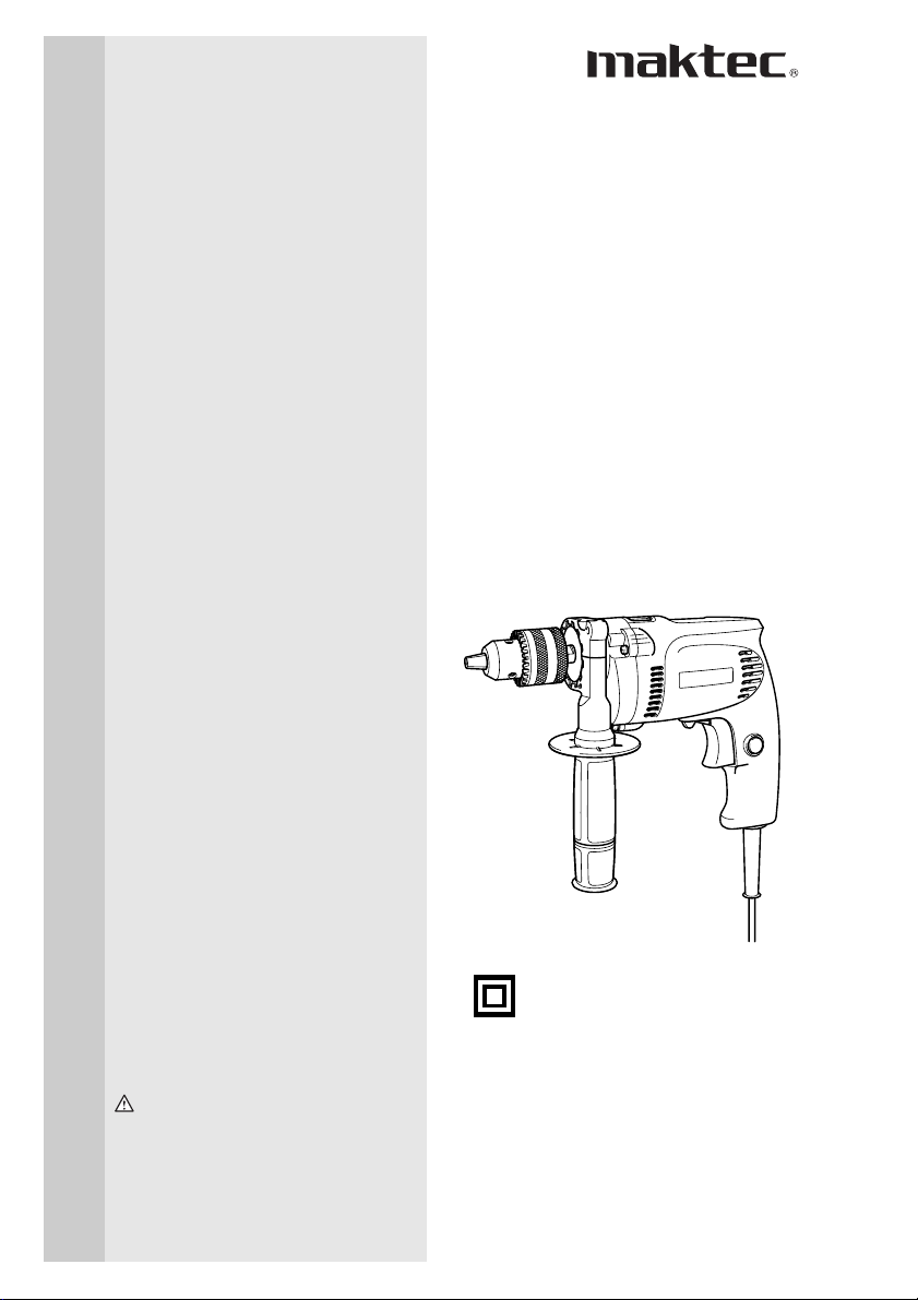
Hammer Drill
MODEL MT810
MODEL MT811
MODEL MT812
MODEL MT813
DOUBLE
INSULATION
INSTRUCTION MANUAL
WARNING:
For your personal safety, READ and UNDERSTAND before using.
SAVE THESE INSTRUCTIONS FOR FUTURE REFERENCE.
001690
Page 2
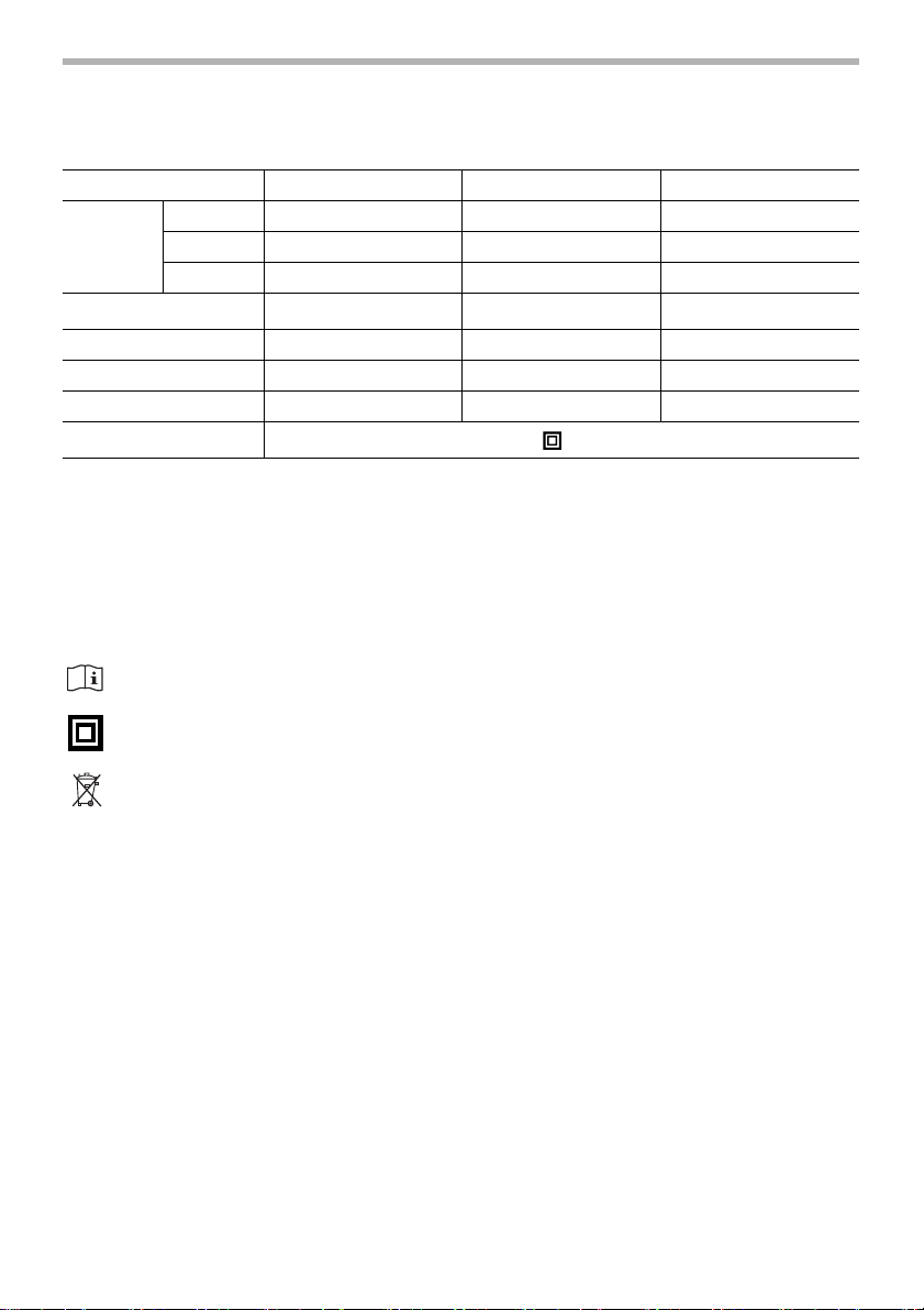
SPECIFICATIONS
Model MT810 MT811/MT812 MT813
Concrete 10 mm 13 mm 16 mm
Capacities
No load speed (Min
Blows per minute 0 - 30,800 0 - 30,800 0 - 45,000
Overall length 258 mm 272 mm 297 mm
Net weight 1.4 kg 1.6 kg 2.0 kg
Safety class
• Manufacturer reserves the right to change specifications without notice.
• Specifications may differ from country to country.
SYMBOLS
The following show the symbols used for the
tool. Be sure that you understand their
meaning before use.
...............Read instruction manual.
...............DOUBLE INSULATION
..............Only for EU countries
Wood 18 mm 18 mm 30 mm
Steel 10 mm 13 mm 13 mm
-1
)
0 - 2,800 0 - 2,800 0 - 3,000
/II
END201-2
Intended use
The tool is intended for impact drilling in
brick, concrete and stone as well as for drilling without impact in wood, metal, ceramic
and plastic.
Power supply
The tool should be connected only to a
power supply of the same voltage as indicated on the nameplate, and can only be
operated on single-phase AC supply. They
Do not dispose of electric
equipment together with
household waste material!
are double-insulated in accordance with
European Standard and can, therefore, also
be used from sockets without earth wire.
For Model MT810/MT811/MT812
In observance of European
Directive 2002/96/EC on
waste electric and electronic
equipment and its implementation in accordance with
national law, electric equipment that have reached the
end of their life must be collected separately and
returned to an environmentally compatible recycling
facility.
For European countries only
Noise and Vibration
The typical A-weighted noise levels are
sound pressure level: 95 dB (A)
sound power level: 106 dB (A)
Uncertainty: 3 dB
– Wear ear protection. –
The typical weighted root mean square
acceleration value is 10 m/s
These values have been obtained according
to EN60745.
2
2
.
Page 3

For Model MT813
For European countries only
Noise and Vibration
The typical A-weighted noise levels are
sound pressure level: 98 dB (A)
sound power level: 109 dB (A)
Uncertainty: 3 dB
– Wear ear protection. –
The typical weighted root mean square
acceleration value is 10 m/s2.
These values have been obtained according
to EN60745.
EC-DECLARATION OF CONFORMITY
We declare under our sole responsibility
that this product is in compliance with the
following standards of standardized documents, EN60745, EN55014, EN61000 in
accordance with Council Directives, 89/336/
EEC, 98/37/EC.
Yasuhiko Kanzaki CE 2005
Director
MAKITA INTERNATIONAL EUROPE LTD.
Michigan Drive, Tongwell, Milton Keynes,
Bucks MK15 8JD, ENGLAND
Responsible manufacturer:
Makita Corporation Anjo Aichi Japan
GENERAL SAFETY RULES GEA001-3
WARNING:
Read all instructions. Failure to follow all instructions listed below
may result in electric shock, fire and/or serious injury. The term
“power tool” in all of the warnings listed below refers to your mainsoperated (corded) power tool or battery-operated (cordless) power
tool.
SAVE THESE INSTRUCTIONS
Work area safety
1. Keep work area clean and well lit. Cluttered
and dark areas invite accidents.
2. Do not operate power tools in explosive
atmospheres, such as in the presence of
flammable liquids, gases or dust. Powe r
tools create sparks which may ignite the dust
or fumes.
3. Keep children and bystanders away while
operating a power tool. Distractions can
cause you to lose control.
3
Page 4

Electrical safety
4. Power tool plugs must match the outlet.
Never modify the plug in any way. Do not
use any adapter plugs with earthed
(grounded) power tools. Unmodified plugs
and matching outlets will reduce risk of electric shock.
5. Avoid body contact with earthed or
grounded surfaces such as pipes, radiators, ranges and refrigerators. There is an
increased risk of electric shock if your body is
earthed or grounded.
6. Do not expose power tools to rain or wet
conditions. Water entering a power tool will
increase the risk of electric shock.
7. Do not abuse the cord. Never use the cord
for carrying, pulling or unplugging the
power tool. Keep cord away from heat, oil,
sharp edges or moving parts. Damaged or
entangled cords increase the risk of electric
shock.
8. When operating a power tool outdoors,
use an extension cord suitable for outdoor use. Use of a cord suitable for outdoor
use reduces the risk of electric shock.
Personal safety
9. Stay alert, watch what you are doing and
use common sense when operating a
power tool. Do not use a power tool while
you are tired or under the influence of
drugs, alcohol or medication. A moment of
inattention while operating power tools may
result in serious personal injury.
10. Use safety equipment. Always wear eye
protection. Safety equipment such as dust
mask, non-skid safety shoes, hard hat, or
hearing protection used for appropriate conditions will reduce personal injuries.
11. Avoid accidental starting. Ensure the
switch is in the off-position before plugging in. Carrying power tools with your finger
on the switch or plugging in power tools that
have the switch on invites accidents.
12. Remove any adjusting key or wrench
before turning the power tool on. A wrench
or a key left attached to a rotating part of the
power tool may result in personal injury.
13. Do not overreach. Keep proper footing
and balance at all times. This enables bet-
ter control of the power tool in unexpected situations.
14. Dress properly. Do not wear loose clothing or jewellery. Keep your hair, clothing,
and gloves away from moving parts.
Loose clothes, jewellery or long hair can be
caught in moving parts.
15. If devices are provided for the connection
of dust extraction and collection facilities,
ensure these are connected and properly
used. Use of these devices can reduce dust-
related hazards.
Power tool use and care
16. Do not force the power tool. Use the correct power tool for your application. The
correct power tool will do the job better and
safer at the rate for which it was designed.
17. Do not use the power tool if the switch
does not turn it on and off. Any power tool
that cannot be controlled with the switch is
dangerous and must be repaired.
18. Disconnect the plug from the power
source and/or the battery pack from the
power tool before making any adjustments, changing accessories, or storing
power tools. Such preventive safety mea-
sures reduce the risk of starting the power
tool accidentally.
19. Store idle power tools out of the reach of
children and do not allow persons unfamiliar with the power tool or these instructions to operate the power tool. Power
tools are dangerous in the hands of untrained
users.
20. Maintain power tools. Check for misalignment or binding of moving parts, breakage of parts and any other condition that
may affect the power tools operation. If
4
Page 5

damaged, have the power tool repaired
before use. Many accidents are caused by
poorly maintained power tools.
21. Keep cutting tools sharp and clean. Prop-
erly maintained cutting tools with sharp cutting edges are less likely to bind and are
easier to control.
22. Use the power tool, accessories and tool
bits etc. in accordance with these instructions and in the manner intended for the
particular type of power tool, taking into
account the working conditions and the
work to be performed. Use of the power tool
for operations different from those intended
could result in a hazardous situation.
Service
23. Have your power tool serviced by a qualified repair person using only identical
replacement parts. This will ensure that the
safety of the power tool is maintained.
24. Follow instruction for lubricating and
changing accessories.
25. Keep handles dry, clean and free from oil
and grease.
SPECIFIC SAFETY RULES GEB003-2
DO NOT let comfort or familiarity with product (gained from
repeated use) replace strict adherence to hammer drill safety
rules. If you use this power tool unsafely or incorrectly, you can
suffer serious personal injury.
1. Wear ear protectors with impact drills.
Exposure to noise can cause hearing loss.
2. Use auxiliary handles supplied with the
tool. Loss of control can cause personal
injury.
3. Hold power tools by insulated gripping
surfaces when performing an operation
where the cutting tool may contact hidden
wiring or its own cord. Contact with a “live”
wire will make exposed metal parts of the tool
“live” and shock the operator.
4. Always be sure you have a firm footing.
Be sure no one is below when using the
tool in high locations.
5. Hold the tool firmly with both hands.
6. Keep hands away from rotating parts.
7. Do not leave the tool running. Operate the
tool only when hand-held.
8. Do not touch the bit or the workpiece
immediately after operation; they may be
extremely hot and could burn your skin.
9. Some material contains chemicals which
may be toxic. Take caution to prevent dust
inhalation and skin contact. Follow material supplier safety data.
5
Page 6

SAVE THESE INSTRUCTIONS
WARNING:
MISUSE or failure to follow the safety rules stated in this
instruction manual may cause serious personal injury.
6
Page 7

ASSEMBLY
1
2
5
1. Grip base
2. Side grip(auxiliary handle)
3. Teeth
4. Protrusion
5. Loosen
6. Tighten
3
4
6
001691
Installing side grip (auxiliary handle)
CAUTION:
• Always be sure that the tool is switched off and
unplugged before installing or removing the side grip.
Always use the side grip to ensure operating safety. Install
the side grip so that the teeth on the grip fit in between the
protrusions on the tool barrel. Then tighten the grip by turning clockwise at the desired position. It may be swung 360°
so as to be secured at any position.
001692
Installing or removing drill bit
1
1. Drill chuck
2. Chuck key
1
1. Sleeve
2. Ring
2
CAUTION:
• Always be sure that the tool is switched off and
unplugged before installing or removing the bit.
For Model MT810/MT811/MT813
To install the bit, place it in the chuck as far as it will go.
Tighten the chuck by hand. Place the chuck key in each of
the three holes and tighten clockwise. Be sure to tighten all
three chuck holes evenly. To remove the bit, turn the chuck
key counterclockwise in just one hole, then loosen the chuck
by hand.
After using the chuck key, be sure to return it to the original
position.
For Model MT812
004365
Hold the ring and turn the sleeve counterclockwise to open
the chuck jaws. Place the bit in the chuck as far as it will go.
Hold the ring firmly and turn the sleeve clockwise to tighten
the chuck.
To remove the bit, hold the ring and turn the sleeve counter-
2
clockwise.
7
Page 8

1
1. Side grip
2. Depth gauge
3. Grip base
FUNCTIONAL
DESCRIPTION
1
2
1. Switch trigger
2. Lock button
001693
2
3
001694
Depth gauge (optional accessory)
The depth gauge is convenient for drilling holes of uniform
depth. Loosen the side grip and insert the depth gauge into
the hole in the grip base. Adjust the depth gauge to the
desired depth and tighten the side grip.
NOTE:
The depth gauge cannot be used at the position where the
depth gauge strikes against the gear housing.
Switch action
CAUTION:
• Before plugging in the tool, always check to see that the
switch trigger actuates properly and returns to the “OFF”
position when released.
To start the tool, simply pull the switch trigger. Tool speed is
increased by increasing pressure on the switch trigger.
Release the switch trigger to stop. For continuous operation,
pull the switch trigger and then push in the lock button. To
stop the tool from the locked position, pull the switch trigger
fully, then release it.
A
B
1
1. Reversing switch lever
001695
Reversing switch action
This tool has a reversing switch to change the direction of
rotation. Move the reversing switch lever to the position (A
side) for clockwise rotation or to the position (B side) for
counterclockwise rotation.
CAUTION:
• Always check the direction of rotation before operation.
• Use the reversing switch only after the tool comes to a
complete stop. Changing the direction of rotation before
the tool stops may damage the tool.
8
Page 9

001696
Selecting the action mode
This tool has an action mode change lever. For rotation with
hammering, slide the action mode change lever to the right
( symbol). For rotation only, slide the action mode change
lever to the left ( symbol).
1
1. Action mode changing lever
OPERATION
CAUTION:
• Always slide the action mode change lever all the way to
your desired mode position. If you operate the tool with
the lever positioned halfway between the mode symbols,
the tool may be damaged.
Hammer drilling operation
CAUTION:
• There is tremendous and sudden twisting force exerted
on the tool/bit at the time of hole break-through, when
the hole becomes clogged with chips and particles, or
when striking reinforcing rods embedded in the
concrete. Always use the side grip (auxiliary handle) and
firmly hold the tool by both side grip and switch handle
during operations. Failure to do so may result in the loss
of control of the toll and potentially serve injury.
When drilling in concrete, granite, tile, etc., slide the action
mode change lever to the position of symbol to use “rota-
tion with hammering” action. Be sure to use a tungsten-carbide tipped bit. Do not apply more pressure when the hole
becomes clogged with chips or particles. Instead, run the
tool at an idle, then remove the bit partially from the hole. By
repeating this several times, the hole will be cleaned out.
After drilling the hole, use the blow-out bulb to clean the dust
out of the hole.
Drilling operation
When drilling in wood, metal or plastic materials, slide the
action mode change lever to the position of symbol to use
“rotation only” action.
Drilling in wood
When drilling in wood, the best results are obtained with
wood drills equipped with a guide screw. The guide screw
makes drilling easier by pulling the bit into the workpiece.
9
Page 10

Drilling in metal
To prevent the bit from slipping when starting a hole, make
an indentation with a center-punch and hammer at the point
to be drilled. Place the point of the bit in the indentation and
start drilling. Use a cutting lubricant when drilling metals. The
exceptions are iron and brass which should be drilled dry.
CAUTION:
• Pressing excessively on the tool will not speed up the
drilling. In fact, this excessive pressure will only serve to
damage the tip of your bit, decrease the tool
performance and shorten the service life of the tool.
• There is a tremendous force exerted on the tool/bit at the
time of hole break through. Hold the tool firmly and exert
care when the bit begins to break through the workpiece.
• A stuck bit can be removed simply by setting the
reversing switch to reverse rotation in order to back out.
However, the tool may back out abruptly if you do not
hold it firmly.
• Always secure small workpieces in a vise or similar holddown device.
MAINTENANCE
CAUTION:
• Always be sure that the tool is switched off and
unplugged before carrying out any work on the tool.
To maintain product safety and reliability, repairs, maintenance or adjustment should be carried out by an Makita
Authorized Service Center.
10
Page 11

Memo
11
Page 12

884431C225
Makita Corporation Anjo, Aichi, Japan
 Loading...