

Makita MT80A, MT80B Technical Information
PRODUCT
CONCEPT AND MAIN APPLICATIONS
P 1/ 12
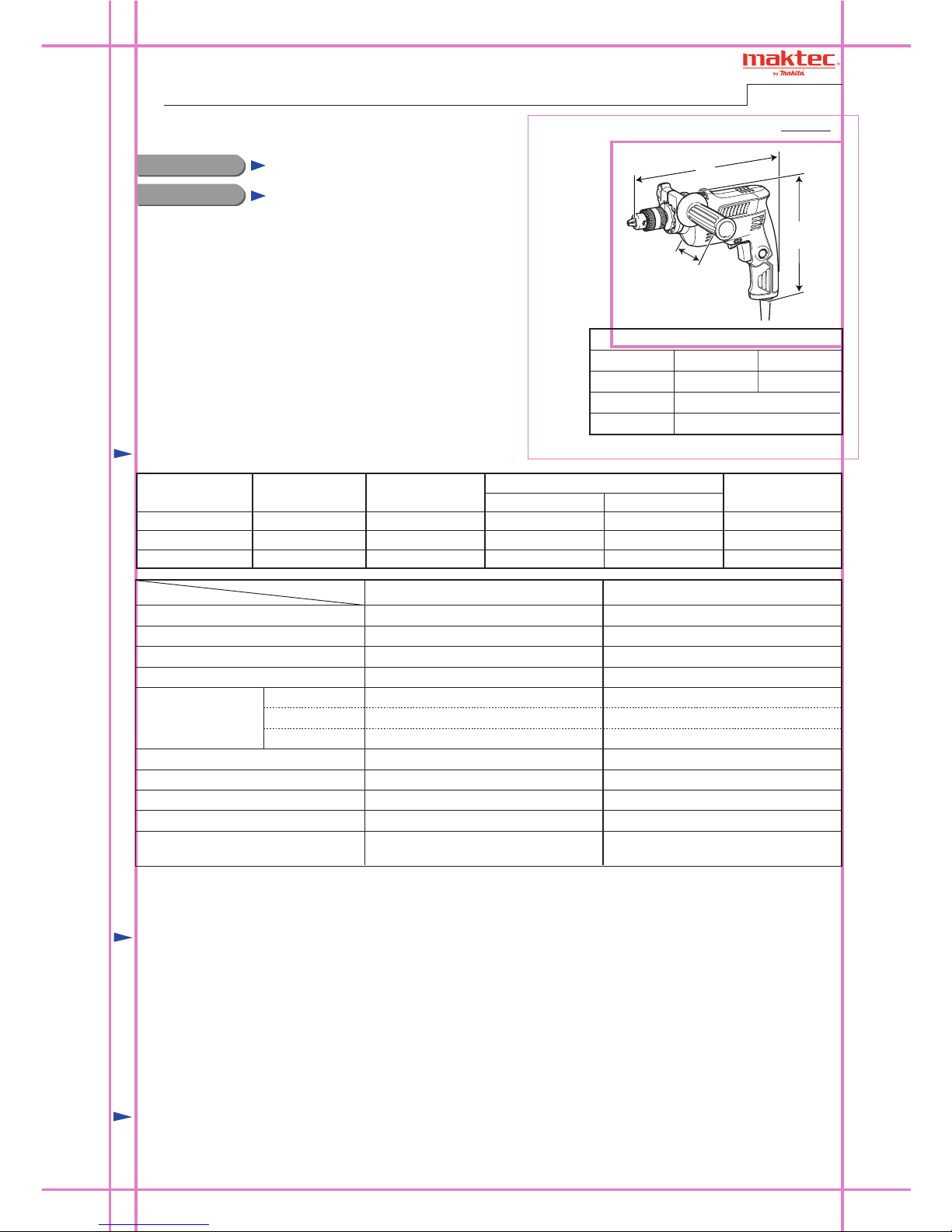
Specification
Standard equipment
Optional accessories
Note: The standard equipment for the tool shown above may vary by country.
Model No.
Description
MT80A, MT80B
Hammer Drills 10mm (3/8"), 16mm (5/8")
Models MT80A/ MT80B have been developed as maktec brand
hammer drills 10mm (3/8")/ 16mm (5/8"), mainly for the emerging
countries.
New maktec design is employed to eliminate white printing and
polygonal line from maktec logo/ elastomer from handle for the cost
effectiveness.
Depth gauge
230
240
50/60
50/60
2.3
2.2
500
500
250
250
350
220 50/602.4 500 250 350
350
Continuous Rating (W)
Voltage (V) Cycle (Hz)
Input Output
Max. Output (W)Current (A)
Dimensions: mm ( " )
Width (W)
Height (H)
Length (L)
262 (10-3/8)
MT80B
254 (10)
MT80A
196 (7-3/4)
70 (2-3/4)
Chuck capacity: mm (")
Chuck type
Reverse switch
Impacts per min.: min.
ˉ¹= ipm
Capacities: mm (") Steel
Concrete
Wood
Protection against electric shock
Power supply cord: m (ft)
Weight according to
EPTA-Procedure 01/2003*: kg (lbs)
0 - 2,900
Model No.
MT80B
0 - 43,500
Keyed
1.5 - 13 (1/16 - 1/2)
16 (5/8)
13 (1/2)
20 (13/16)
Yes
Double insulation
1.7 (3.7)
2.0 (6.6)
Variable speed control by trigger Yes
0 - 2,900
MT80A
0 - 43,500
Keyed
1.5 - 10 (1/16 - 3/8)
10 (3/8)
10 (3/8)
20 (13/16)
Yes
Double insulation
1.6 (3.4)
2.0 (6.6)
Yes
* with Side grip
Chuck key S10 (MT80A) ........................................ 1
Chuck key S13 (MT80B) ........................................ 1
Key holder 10 .......................................................... 1 (for some countries only)
Side grip .................................................................. 1
Plastic carrying case (MT80B) ............................... 1 (for “K model” only)
No load speed: min.
ˉ¹=rpm
Specification
T
ECHNICAL INFORMATION
W
L
H
P 2/ 12
Repair
[1] NECESSARY REPAIRING TOOLS
CAUTION: Repair the machine in accordance with “Instruction manual” or “Safety instructions”.
Code No. Description Use for
1R004 Retaining ring pliers ST-2
Ratchet head 12.7 (for 1R223)
1/4” Hex. shank bit for M8
removing / mounting Ring spring 13
1R029
1R031
1R139
1R165
1R223
1R224
1R231
1R258
1R278
1R298
Bearing setting pipe 23-15.2 assembling Helical gear 39 to Spindle
Bearing setting pipe 28-20.2 assembling Cam complete to Cam holder
fixing Spindle when removing / mounting Drill chuck
holding Helical gear 39 when separating Spindle from Helical gear 39
holding Cam holder when disassembling/ assembling Cam complete
removing / assembling
Drill chucks
for both 10 mm and 13 mm Drill chucks
for 13 mm Drill chuck
for 10 mm Drill chuck
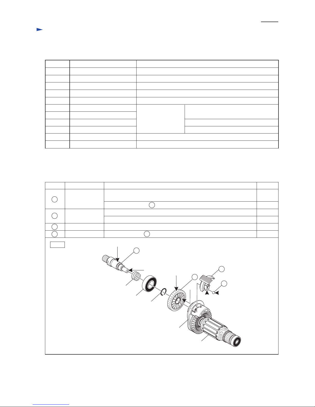
[2] LUBRICATION
Apply Makita grease N. No.2 to the following portions designated with the black triangle to protect parts and product
from unusual abrasion.
Fig. 1
Item No. Description
Spindle
a little
a little
3.0g
1.7g
a little
a little
a: Drum portion for smooth hammering in the inner ring
of Ball bearing 6002LLB
b: Spindle end where 10 Steel ball 5 contacts
Steel ball 5
Change lever
accepting hole for 10 Steel ball 5
Helical gear 39
c: Teeth portion for smooth engaging with Armature’s gear
d: Cam portion for smooth engaging with Cam on Cam holder complete
Whole portion
AmountPortion to lubricate
5
b
c
d
a
5
9
9
10
10
Ball bearing 6002LLB
Compression spring 16
Ring spring 13
Armature
Cam holder
complete
12
12
Drill chuck extractor
Ring spring setting tool B
Torque wrench shaft 20-90N·m
Round bar for arbor 4-50
Hex bar 10 with square socket
V block
disassembling Cam complete from Cam holder
P 3/ 12
Repair
[3] DISASSEMBLY/ASSEMBLY
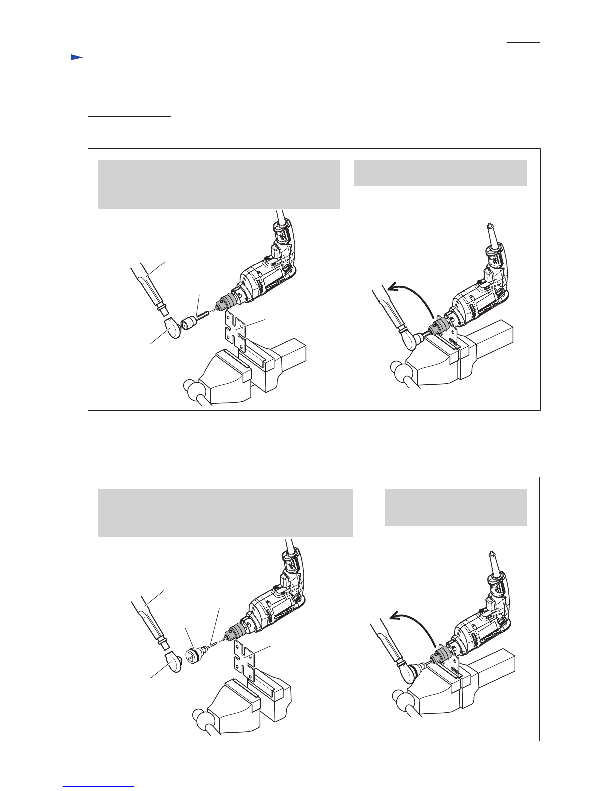
[3] -1A. 13mm Drill Chuck of model MT80B
DISASSEMBLING
Remove 13mm Drill chuck as drawn in Fig. 2A.
Remove 10mm Drill chuck as drawn in Fig. 2B.
1. Fix 1R139 firmly with vise. Then attach 1R298 to
13mm Drill chuck, and then fix the machine to 1R139
by fitting the flat portion of Spindle to the groove of 1R139.
2. Attach 1R224 to 1R223 and set them to 1R298.
3. Turn 1R223 counter clockwise to remove
13mm Drill chuck from the machine.
1R139
1R298
1R224
1R223
Fig. 2A
Fig. 2B
[3] -1B. 10mm Drill Chuck of model MT80A
1R139
1R224
1R231
Bit adapter
1R223
1. Fix 1R139 firmly with vise. Then attach 1R231 and Bit adapter
to 10mm Drill chuck, and then fix the machine to 1R139
by fitting the flat portion of Spindle to the groove of 1R139.
2. Attach 1R224 to 1R223 and set them Bit adapter.
3. Turn 1R223 counter clockwise
to remove 10mm Drill chuck
from the machine.
P 4/ 12
Repair
[3] DISASSEMBLY/ASSEMBLY
[3] -1A. 13mm Drill Chuck of model MT80B (cont.)
-1B. 10mm Drill Chuck of model MT80A (cont.)
ASSEMBLING
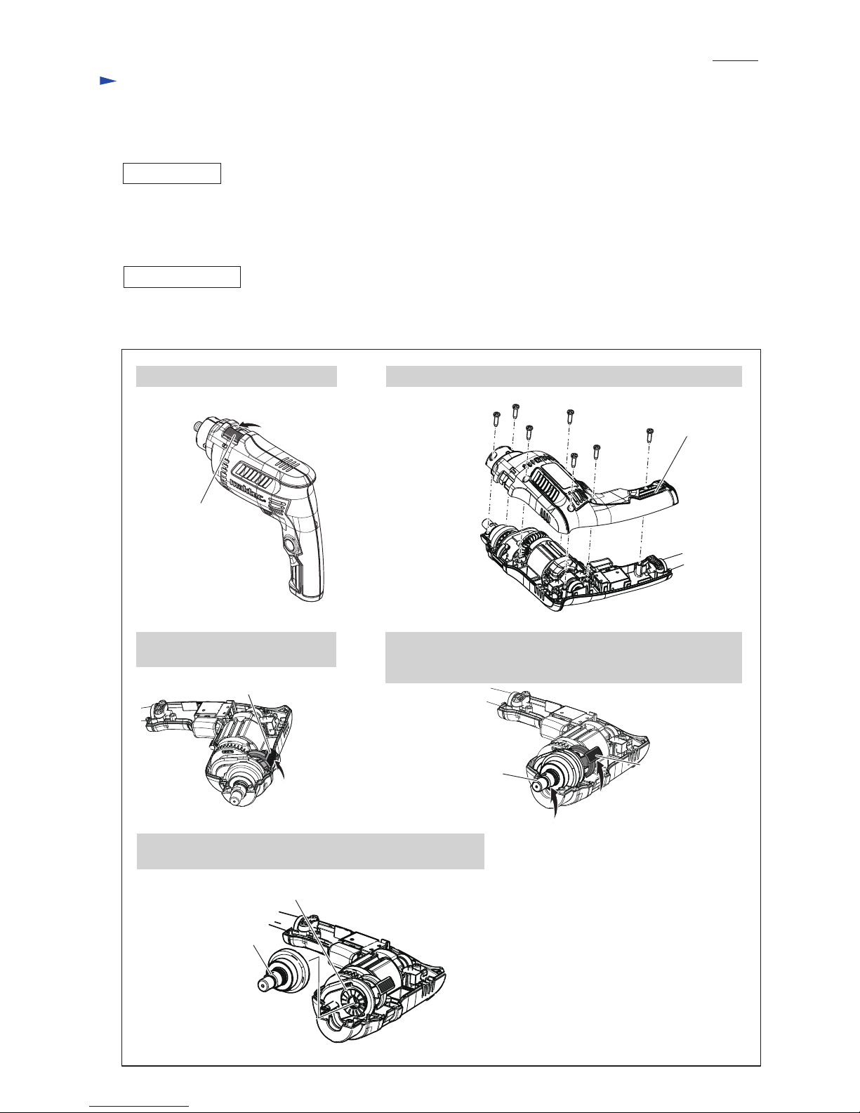
[3] -2. Helical Gear 39, Ball Bearing 6002LLB
DISASSEMBLING
Assemble by reversing the disassembly procedure. Refer to Fig. 2A or Fig. 2B.
Note: Set the fastening torque of 1R223 to 24.5N·m ~ 29.4 N·m (250 Kg f·cm ~ 300 Kg f·cm) and turn 1R223 clockwise.
(1) Remove Drill chuck as drawn in Fig. 2A or Fig. 2B.
(2) Remove Spindle section from the machine as illustrated in Fig. 3.
Fig. 3
3. Shift Change lever to Hammer
drill mode
1. Shift Change lever to Drill mode. 2. Remove Housing (R) by loosening seven 4x18 Tapping screws.
4. Hold Spindle and Change lever by hand, then Lift up Spindle
and Change lever while turning them counter clockwise
viewing them from Drill chuck side.
5. Pull off the Spindle section (Spindle, Ball bearing 6002LLB,
Compression spring 16) from Cam holder complete.
Change lever
Cam holder complete
Housing (R)
4x18 Tapping screw
(7 pcs.)
Change lever
Spindle
Change
lever
Spindle section
 Loading...