

Page 1
GB
MT605
MT606
MT607
F
D
I
NL
E
P
DK
GR Τρυπάνι Οδηγίες χρήσεως
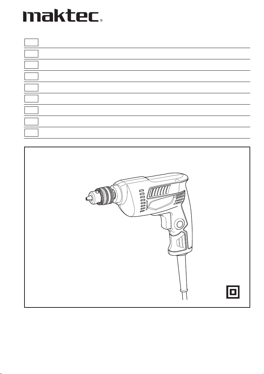
Drill Instruction Manual
Perceuse Manuel d’instructions
Bohrmaschine Betriebsanleitung
Trapano Istruzioni per l’uso
Boormachine Gebruiksaanwijzing
Taladro Manual de instrucciones
Furadeira Manual de instruções
Boremaskine Brugsanvisning
Page 2
4
A
1
2
B
3
12
5
6
34
2
Page 3
ENGLISH (Original instructions)
Explanation of general view
1 Switch trigger
2 Lock button
SPECIFICATIONS
Model MT605 MT606 MT607
Capacities
Steel ........................................................................... 10 mm 10 mm 10 mm
Wood .........................................................................25 mm 25 mm 25 mm
No load speed (min
Overall length ............................................................... 229 mm 229 mm 234 mm
Net weight ..................................................................... 1.3 kg 1.3 kg 1.3 kg
Safety class ................................................................... /II /II /II
–1
) .................................................. 3,000 0 – 3,000 0 – 3,000
3 Reversing switch lever
4 Chuck key
5 Sleeve
6 Ring
• Due to our continuing program of research and devel-
opment, the specifications herein are subject to change
without notice.
• Specifications may differ from country to country.
• Weight according to EPTA-Procedure 01/2003
Intended use
The tool is intended for drilling in wood, metal and plastic.
Power supply
The tool should be connected only to a power supply of
the same voltage as indicated on the nameplate, and can
only be operated on single-phase AC supply. They are
double-insulated and can, therefore, also be used from
sockets without earth wire.
General Power Tool Safety Warnings
ENE032-1
ENF002-2
GEA010-1
WARNING Read all safety warnings and all
instructions. Failure to follow the warnings and
instructions may result in electric shock, fire and/or
serious injury.
Save all warnings and instructions for future reference.
GEB001-6
DRILL SAFETY WARNINGS
1. Use auxiliary handle(s), if supplied with the tool.
Loss of control can cause personal injury.
2. Hold power tool by insulated gripping surfaces,
when performing an operation where the cutting
accessory may contact hidden wiring or its own
cord. Cutting accessory contacting a “live” wire may
make exposed metal parts of the power tool “live”
and could give the operator an electric shock.
3. Always be sure you have a firm footing.
Be sure no one is below when using the tool in
high locations.
4. Hold the tool firmly.
5. Keep hands away from rotating parts.
6. Do not leave the tool running. Operate the tool
only when hand-held.
7. Do not touch the drill bit or the workpiece imme-
diately after operation; they may be extremely
hot and could burn your skin.
8. Some material contains chemicals which may be
toxic. Take caution to prevent dust inhalation
and skin contact. Follow material supplier safety
data.
SAVE THESE INSTRUCTIONS.
WARNING:
DO NOT let comfort or familiarity with product
(gained from repeated use) replace strict adherence
to safety rules for the subject product. MISUSE or
failure to follow the safety rules stated in this instruction manual may cause serious personal injury.
FUNCTIONAL DESCRIPTION
CAUTION:
• Always be sure that the tool is switched off and
unplugged before adjusting or checking function on the
tool.
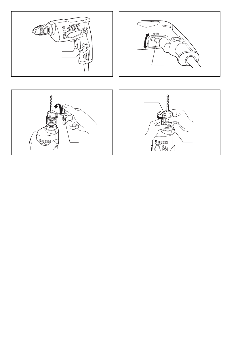
Switch action (Fig. 1)
CAUTION:
• Before plugging in the tool, always check to see the
switch trigger actuates properly and returns to the
“OFF” position when released.
For MT605
To start the tool, simply pull the switch trigger. Release
the switch trigger to stop.
For continuous operation, pull the switch trigger and then
push in the lock button.
To stop the tool from the locked position, pull the switch
trigger fully, then release it.
For MT606, MT607
To start the tool, simply pull the switch trigger. Tool speed
is increased by increasing pressure on the switch trigger.
Release the switch trigger to stop.
For continuous operation, pull the switch trigger and then
push in the lock button.
To stop the tool from the locked position, pull the switch
trigger fully, then release it.
3
Page 4

Reversing switch action (Fig. 2)
For MT606, MT607
This tool has a reversing switch to change the direction
of rotation. Move the reversing switch lever to the
position (A side) for clockwise rotation or to the E position (B side) for counterclockwise rotation.
CAUTION:
• Always check the direction of rotation before operation.
• Use the reversing switch only after the tool comes to a
complete stop. Changing the direction of rotation
before the tool stops may damage the tool.
ASSEMBLY
CAUTION:
• Always be sure that the tool is switched off and
unplugged before carrying out any work on the tool.
Installing or removing drill bit
CAUTION:
• Always be sure that the tool is switched off and
unplugged before installing or removing the bit.
For MT605, MT606 (Fig. 3)
To install the bit, place it in the chuck as far as it will go.
Tighten the chuck by hand. Place the chuck key in each
of the three holes and tighten clockwise. Be sure to
tighten all three chuck holes evenly.
To remove the bit, turn the chuck key counterclockwise in
just one hole, then loosen the chuck by hand.
For MT607 (Fig. 4)
Hold the ring and turn the sleeve counterclockwise to
open the chuck jaws. Place the bit in the chuck as far as
it will go. Hold the ring firmly and turn the sleeve clockwise to tighten the chuck.
To remove the bit, hold the ring and turn the sleeve counterclockwise.
OPERATION
Drilling operation
Drilling in wood
When drilling in wood, the best results are obtained with
wood drills equipped with a guide screw. The guide
screw makes drilling easier by pulling the bit into the
workpiece.
Drilling in metal
To prevent the bit from slipping when starting a hole,
make an indentation with a center-punch and hammer at
the point to be drilled. Place the point of the bit in the
indentation and start drilling.
Use a cutting lubricant when drilling metals. The exceptions are iron and brass which should be drilled dry.
CAUTION:
• Pressing excessively on the tool will not speed up the
drilling. In fact, this excessive pressure will only serve
to damage the tip of your bit, decrease the tool performance and shorten the service life of the tool.
• There is a tremendous force exerted on the tool/bit at
the time of hole break through. Hold the tool firmly and
exert care when the bit begins to break through the
workpiece.
• Always secure small workpieces in a vise or similar
hold-down device.
MAINTENANCE
CAUTION:
• Always be sure that the tool is switched off and
D
unplugged before carrying out any work on the tool.
• Never use gasoline, benzine, thinner, alcohol or the
like. Discoloration, deformation or cracks may result.
To maintain product SAFETY and RELIABILITY, repairs,
any other maintenance or adjustment should be performed by Makita Authorized Service Centres, always
using Makita replacement parts.
Noise
The typical A-weighted noise level determined according
to EN60745:
Sound pressure level (L
Uncertainty (K): 3 dB (A)
The noise level under working may exceed 80 dB (A).
Wear ear protection
Vibration
The vibration total value (tri-axial vector sum) determined
according to EN60745:
Work mode: drilling into metal
Vibration emission (
Uncertainty (K): 1.5 m/s
• The declared vibration emission value has been measured in accordance with the standard test method and
may be used for comparing one tool with another.
• The declared vibration emission value may also be
used in a preliminary assessment of exposure.
WARNING:
• The vibration emission during actual use of the power
tool can differ from the declared emission value
depending on the ways in which the tool is used.
• Be sure to identify safety measures to protect the operator that are based on an estimation of exposure in the
actual conditions of use (taking account of all parts of
the operating cycle such as the times when the tool is
switched off and when it is running idle in addition to
the trigger time).
a
h, D
): 77 dB (A)
pA
): 3.0 m/s
2
2
ENG905-1
ENG900-1
ENG901-1
4
Page 5

For European countries only
ENH101-15
EC Declaration of Conformity
We Makita Corporation as the responsible manufacturer declare that the following Makita machine(s):
Designation of Machine: Drill
Model No./ Type: MT605, MT606, MT607
are of series production and
Conforms to the following European Directives:
2006/42/EC
And are manufactured in accordance with the following
standards or standardised documents:
EN60745
The technical documentation is kept by our authorized
representative in Europe who is:
Makita International Europe Ltd.
Michigan Drive, Tongwell,
Milton Keynes, Bucks MK15 8JD, England
3. 11. 2010
Tomoyasu Kato
Director
Makita Corporation
3-11-8, Sumiyoshi-cho,
Anjo, Aichi, 446-8502, JAPAN
5
Page 6
FRANÇAIS (Instructions originales)
Descriptif
1 Gâchette de l’interrupteur
2 Bouton de verrouillage
SPÉCIFICATIONS
Modèle MT605 MT606 MT607
Capacités
Acier .......................................................................... 10 mm 10 mm 10 mm
Bois ........................................................................... 25 mm 25 mm 25 mm
Vitesse à vide (min
Longueur totale ............................................................ 229 mm 229 mm 234 mm
Poids net ...................................................................... 1,3 kg 1,3 kg 1,3 kg
Niveau de sécurité ........................................................ /II /II /II
• Étant donné l’évolution constante de notre programme
de recherche et de développement, les spécifications
contenues dans ce manuel sont sujettes à modification
sans préavis.
• Les spécifications peuvent varier suivant les pays.
• Poids selon la procédure EPTA 01/2003
Utilisations
L’outil est prévu pour le perçage et le vissage dans le
–1
) ................................................... 3 000 0 – 3 000 0 – 3 000
bois, le métal et le plastique.
Alimentation
L’outil ne devra être raccordé qu’à une alimentation de la
même tension que celle qui figure sur la plaque signalétique, et il ne pourra fonctionner que sur un courant secteur monophasé. Réalisé avec une double isolation, il
peut de ce fait être alimenté sans mise à la terre.
Consignes de sécurité générales pour outils électriques
MISE EN GARDE Veuillez lire toutes les mises en
garde et toutes les instructions. Il y a risque de choc
électrique, d’incendie et/ou de blessure grave si les
mises en garde et les instructions ne sont pas
respectées.
Conservez toutes les mises en garde et instructions
pour référence ultérieure.
3 Inverseur
4 Clé de mandrin
ENE032-1
ENF002-2
GEA010-1
5 Manchon
6 Bague
CONSIGNES DE SÉCURITÉ POUR
LA PERCEUSE
1. Utilisez la ou les poignée(s) auxiliaire(s), si l’outil
en possède. Toute perte de maîtrise comporte un
risque de blessure.
2. Saisissez l’outil électrique uniquement par ses
surfaces de poigne isolées lorsque vous effectuez des travaux au cours desquels l’accessoire
tranchant peut entrer en contact avec des fils
cachés ou avec le cordon d’alimentation de
Le contact de l’accessoire tranchant avec un
l’outil.
fil sous tension peut également mettre sous tension
les parties métalliques exposées de l’outil électrique,
causant ainsi un choc électrique chez l’utilisateur.
3. Veillez toujours à avoir une bonne assise.
Veillez à ce qu’il n’y ait personne en-dessous
quand vous utilisez l’outil dans des endroits élevés.
4. Tenez votre outil fermement.
5. N’approchez pas les mains des pièces en mouvement.
6. Ne vous éloignez pas de l’outil pendant qu’il
fonctionne. Ne faites marcher l’outil que lorsque
vous le tenez en main.
7. Ne touchez pas le foret ni la pièce tout de suite
après l’utilisation, car ils seraient extrêmement
chauds et pourraient vous brûler.
8. Certains matériaux contiennent des produits chimiques qui peuvent être toxiques. Prenez les
précautions nécessaires pour ne pas inhaler les
poussières qu’ils dégagent et pour éviter tout
contact avec la peau. Conformez-vous aux consignes de sécurité du fabricant.
CONSERVEZ CES INSTRUCTIONS.
AVERTISSEMENT :
NE vous laissez PAS tromper (au fil d’une utilisation
répétée) par un sentiment d’aisance et de familiarité
avec le produit, en négligeant le respect rigoureux
des consignes de sécurité qui accompagnent le produit en question. La MAUVAISE UTILISATION de
l’outil ou l’ignorance des consignes de sécurité indiquées dans ce manuel d’instructions peut entraîner
une blessure grave.
GEB001-6
6
Page 7
DESCRIPTION DU FONCTIONNEMENT
ATTENTION :
• Assurez-vous toujours que l’outil est hors tension et
débranché avant d’ajuster l’outil ou de vérifier son fonctionnement.
Interrupteur (Fig. 1)
ATTENTION :
• Avant de brancher l’outil, assurez-vous toujours que la
gâchette fonctionne correctement et qu’elle revient en
position “OFF” une fois relâchée.
Pour MT605
Pour mettre l’outil en route, il suffit de tirer sur la gâchette
de l’interrupteur. Pour arrêter l’outil, relâchez la gâchette
de l’interrupteur.
Pour obtenir un fonctionnement continu, tirez sur la
gâchette de l’interrupteur et appuyez sur le bouton de
verrouillage.
Pour arrêter l’outil lorsqu’il fonctionne en continu, tirez à
fond sur la gâchette de l’interrupteur et relâchez-la.
Pour MT606, MT607
Pour démarrer l’outil, tirez simplement sur la gâchette.
Plus vous appuyez sur la gâchette, plus la vitesse augmente. Pour l’arrêter, relâchez la gâchette.
Pour obtenir un fonctionnement continu, tirez sur la
gâchette de l’interrupteur et appuyez sur le bouton de
verrouillage.
Pour arrêter l’outil lorsqu’il fonctionne en continu, tirez à
fond sur la gâchette de l’interrupteur et relâchez-la.
Inverseur (Fig. 2)
Pour MT606, MT607
Cet outil est muni d’un inverseur pour modifier le sens de
rotation. Déplacez l’inverseur sur la position D (côté A)
pour une rotation en sens des aiguilles d’une montre, et
sur la position E (côté B) pour une rotation en sens
inverse.
ATTENTION:
• Vérifiez toujours le sens de rotation avant de mettre
l’outil en marche.
• N’actionnez l’inverseur qu’une fois que l’outil est complètement arrêté. Si vous changez le sens de rotation
de l’outil avant l’arrêt de l’outil, vous risquez de
l’endommager.
ASSEMBLAGE
ATTENTION :
• Assurez-vous toujours que l’outil est hors tension et
débranché avant d’effectuer toute intervention sur
l’outil.
Comment installer et retirer les forets
ATTENTION :
• Vérifiez toujours que l’outil est arrêté et que son câble
d’alimentation est débranché avant d’installer ou de
retirer le foret.
Pour MT605, MT606 (Fig. 3)
Pour installer le foret, introduisez-le le plus à fond possible dans le mandrin. Serrez celui-ci à la main. Puis introduisez la clé de mandrin dans chacun des trois trous et
serrez en tournant vers la droite. Veillez à bien serrer les
trois trous de façon égale.
Pour retirer le foret, tournez la clé de mandrin vers la
gauche dans l’un des trois trous seulement, puis desserrez à la main.
Pour MT607 (Fig. 4)
Tenez la bague et tournez le manchon de mandrin dans
le sens rétro-horaire pour ouvrir le mandrin. Placez le
foret dans le mandrin aussi loin que possible. Tenez solidement la bague et tournez le manchon dans le sens
horaire pour serrer le mandrin.
Pour enlever le foret, tenez la bague et tournez le manchon dans le sens rétro-horaire.
UTILISATION
Perçage
Perçage du bois
Pour percer dans du bois, vous obtiendrez les meilleurs
résultats avec un foret en bois doté d’une vis de guidage.
La vis de guidage facilite le perçage en attirant le foret
dans la pièce.
Perçage du métal
Pour empêcher le foret de glisser en début de forage, faites une encoche au point de forage à l’aide d’un poinçon
et d’un marteau. Placez ensuite la pointe du foret dans
l’encoche et commencez à forer.
Quand vous forez dans du métal, utilisez un lubrifiant de
forage. Seuls le fer doux et le laiton peuvent se forer à
sec.
ATTENTION :
• Une pression excessive sur l’outil n’accélère pas le
perçage. Au contraire, elle risque d’endommager la
pointe du foret, de réduire le rendement de l’outil et
donc sa durée de service.
• Il s’exerce une pression considérable sur l’outil/le foret
au moment où le trou se perce. Tenez l’outil fermement
et faites attention lorsque le foret commence à pénétrer
dans la pièce.
• Immobilisez toujours les petites pièces à percer à l’aide
d’un étau ou d’un serre-joints.
ENTRETIEN
ATTENTION :
• Assurez-vous toujours que l’outil est hors tension et
débranché avant d’effectuer toute intervention sur
l’outil.
• N’utilisez jamais d’essence, benzine, diluant, alcool ou
autre produit similaire. Cela risquerait de provoquer la
décoloration, la déformation ou la fissuration de l’outil.
Pour assurer la SÉCURITÉ et la FIABILITÉ du produit,
les réparations, l’entretien ou les réglages doivent être
effectués par un centre d’entretien Makita agréé, au
moyen de pièces de rechange Makita.
7
Page 8
Bruit
Niveau de bruit pondéré A typique, déterminé selon
EN60745 :
Niveau de pression sonore (L
Incertitude (K) : 3 dB (A)
Le niveau de bruit en fonctionnement peut dépasser
80 dB (A).
Vibrations
Valeur totale de vibrations (somme de vecteur triaxial)
déterminée selon EN60745 :
• La valeur d’émission de vibrations déclarée a été
• La valeur d’émission de vibrations déclarée peut aussi
Porter des protecteurs anti-bruit
Mode de travail : perçage dans le métal
Émission de vibrations (
Incertitude (K) : 1,5 m/s
mesurée conformément à la méthode de test standard
et peut être utilisée pour comparer les outils entre eux.
être utilisée pour l’évaluation préliminaire de l’exposi-
a
h, D
2
) : 77 dB (A)
pA
) : 3,0 m/s
ENG905-1
ENG900-1
2
ENG901-1
tion.
AVERTISSEMENT :
• L’émission de vibrations lors de l’usage réel de l’outil
électrique peut être différente de la valeur d’émission
déclarée, suivant la façon dont l’outil est utilisé.
• Les mesures de sécurité à prendre pour protéger l’utili-
sateur doivent être basées sur une estimation de
l’exposition dans des conditions réelles d’utilisation (en
tenant compte de toutes les composantes du cycle
d’utilisation, comme par exemple le moment de sa
mise hors tension, lorsqu’il tourne à vide et le moment
de son déclenchement).
Pour les pays d’Europe uniquement
ENH101-15
Déclaration de conformité CE
Makita Corporation, en tant que fabricant responsable, déclare que la ou les machines suivantes :
Désignation de la machine : Perceuse
N° de modèle / Type : MT605, MT606, MT607
sont produites en série et
sont conformes aux Directives européennes suivantes :
2006/42/CE
et qu’elles sont fabriquées conformément aux normes ou
documents normalisés suivants :
EN60745
La documentation technique est conservée par notre
représentant agréé en Europe, à savoir :
Makita International Europe Ltd.
Michigan Drive, Tongwell,
Milton Keynes, Bucks MK15 8JD, Angleterre
3. 11. 2010
Tomoyasu Kato
Directeur
Makita Corporation
3-11-8, Sumiyoshi-cho,
Anjo, Aichi, 446-8502, JAPAN
8
Page 9
DEUTSCH (Originale Anleitungen)
Übersicht
1 Elektronikschalter
2 Schalterarretierung
TECHNISCHE DATEN
Modell MT605 MT606 MT607
Bohrleistung
Stahl ........................................................................... 10 mm 10 mm 10 mm
Holz ........................................................................... 25 mm 25 mm 25 mm
Leerlaufdrehzahl (min
Gesamtlänge ................................................................229 mm 229 mm 234 mm
Nettogewicht ................................................................. 1,3 kg 1,3 kg 1,3 kg
Sicherheitsklasse........................................................... /II /II /II
• Wir behalten uns vor, Änderungen im Zuge der Ent-
wicklung und des technischen Fortschritts ohne vorhe-
rige Ankündigung vorzunehmen.
• Die technischen Daten können von Land zu Land
abweichen.
• Gewicht nach EPTA-Verfahren 01/2003
Vorgesehene Verwendung
Die Maschine ist für Bohren in Holz, Metall und Kunst-
–1
) ...............................................3 000 0 – 3 000 0 – 3 000
stoff vorgesehen.
Netzanschluss
Die Maschine darf nur an die auf dem Typenschild angegebene Netzspannung angeschlossen werden und
arbeitet nur mit Einphasen-Wechselspannung. Sie ist
doppelt schutzisoliert und kann daher auch an Steckdose
ohne Erdanschluss betrieben werden.
Allgemeine Sicherheitswarnungen für
Elektrowerkzeuge
WARNUNG Lesen Sie alle Sicherheitswarnungen
und Anweisungen durch. Eine Missachtung der unten
aufgeführten Warnungen und Anweisungen kann zu
einem elektrischen Schlag, Brand und/oder schweren
Verletzungen führen.
Bewahren Sie alle Warnungen und Anweisungen für
spätere Bezugnahme auf.
3 Drehrichtungsumschalter
4 Bohrfutterschüssel
FÜR BOHRMASCHINENSICHERHEITSWARNUNGEN
1. Benutzen Sie (einen) Zusatzgriff(e), sofern er
(sie) mit dem Werkzeug geliefert wurde(n). Ver-
ENE032-1
ENF002-2
GEA010-1
lust der Kontrolle kann Verletzungen verursachen.
2. Halten Sie das Elektrowerkzeug nur an den isolierten Griffflächen, wenn Sie Arbeiten ausführen,
bei denen die Gefahr besteht, dass verborgene
Kabel oder das eigene Kabel kontaktiert werden.
Bei Kontakt mit einem Strom führenden Kabel werden
die freiliegenden Metallteile des Elektrowerkzeugs
ebenfalls Strom führend, so dass der Benutzer einen
elektrischen Schlag erleiden kann.
3. Achten Sie stets auf sicheren Stand.
Vergewissern Sie sich bei Einsatz der Maschine
an hochgelegenen Arbeitsplätzen, dass sich
keine Personen darunter aufhalten.
4. Halten Sie die Maschine mit festem Griff.
5. Halten Sie die Hände von rotierenden Teilen fern.
6. Lassen Sie die Maschine nicht unbeaufsichtigt
laufen. Benutzen Sie die Maschine nur mit Handhaltung.
7. Vermeiden Sie eine Berührung des Bohrereinsatzes oder des Werkstücks unmittelbar nach
der Bearbeitung, weil die Teile noch sehr heiß
sind und Hautverbrennungen verursachen können.
8. Manche Materialien können giftige Chemikalien
enthalten. Treffen Sie Vorsichtsmaßnahmen, um
das Einatmen von Arbeitsstaub und Hautkontakt
zu verhüten. Befolgen Sie die Sicherheitsdaten
des Materialherstellers.
BEWAHREN SIE DIESE HINWEISE
SORGFÄLTIG AUF.
WARNUNG:
Lassen Sie sich NICHT durch Bequemlichkeit oder
Vertrautheit mit dem Produkt (durch wiederholten
Gebrauch erworben) von der strikten Einhaltung der
Sicherheitsregeln für das vorliegende Produkt abhalten. MISSBRAUCH oder Missachtung der Sicherheitsvorschriften in dieser Anleitung können
schwere Verletzungen verursachen.
5 Hülse
6 Klemmring
GEB001-6
9
Page 10

FUNKTIONSBESCHREIBUNG
VORSICHT:
• Vergewissern Sie sich vor jeder Einstellung oder Funktionsprüfung der Maschine stets, dass sie ausgeschaltet und vom Stromnetz getrennt ist.
Schalterfunktion (Abb. 1)
VORSICHT:
• Vor dem Anschließen der Maschine an das Stromnetz
stets überprüfen, ob den Elektronikschalter ordnungsgemäß funktioniert und beim Loslassen in die AUSStellung zurückkehrt.
Für MT605
Die Drehzahl erhöht sich durch verstärkte Druckausübung auf den Elektronikschalter. Zum Ausschalten lassen Sie den Schalter los.
Für Dauerbetrieb drücken Sie den Elektronikschalter und
gleichzeitig die Schalterarretierung.
Zum Ausschalten des Dauerbetriebs den Elektronikschalter drücken und wieder loslassen.
Für MT606, MT607
Zum Einschalten der Maschine drücken Sie einfach den
Elektronikschalter. Die Drehzahl erhöht sich durch verstärkte Druckausübung auf den Elektronikschalter. Zum
Ausschalten lassen Sie den Elektronikschalter los.
Für Dauerbetrieb drücken Sie den Elektronikschalter und
gleichzeitig die Schalterarretierung.
Zum Ausschalten des Dauerbetriebs den Elektronikschalter drücken und wieder loslassen.
Drehrichtungsumschalter (Abb. 2)
Für MT606, MT607
Diese Maschine besitzt einen Drehrichtungsumschalter.
Stellen Sie den Drehrichtungsumschalthebel für Rechtsdrehung auf die Stellung D (Seite A) oder für Linksdrehung auf die Stellung E (Seite B).
VORSICHT:
• Prüfen Sie stets die Drehrichtung, bevor Sie mit der
Arbeit beginnen.
• Betätigen Sie den Drehrichtungsumschalter erst, nachdem die Maschine zum vollkommenen Stillstand
gekommen ist. Anderenfalls kann die Maschine
beschädigt werden.
MONTAGE
VORSICHT:
• Vergewissern Sie sich vor der Ausführung von Arbeiten
an der Maschine stets, dass sie ausgeschaltet und vom
Stromnetz getrennt ist.
Montage oder Demontage von
Einsatzwerkzeugen
VORSICHT:
• Vergewissern Sie sich vor der Montage oder Demontage des Einsatzwerkzeugs stets, dass die Maschine
ausgeschaltet und vom Stromnetz getrennt ist.
Für MT605, MT606 (Abb. 3)
Das Einsatzwerkzeug soweit wie möglich in das Borfutter
einsetzen. Das Bohfutten von hand Festziehen. Den
Bohrfutterschlüssel in jede der drei Bohfutter- Bohrungen
einsetzen und im Uhrzeigersinn festziehen. An allen drei
Bohrfutter-Bohrungen gleichmäßig spannen.
Zum Entfernen eines Einsatzwerkzeuges den Bohrfutterschlüssel in einer Bohrfutter-Bohrung gegen den Uhrzeigersinn drehen. Danach kann das Bohrfutter von Hand
gelöst werden.
Für MT607 (Abb. 4)
Halten Sie den Klemmring und drehen Sie die Hülse
gegen den Uhrzeigersinn, um das Bohrfutter zu öffnen.
Das Einsatzwerkzeug so weit wie möglich in das Bohrfutter einsetzen. Zum Spannen den Klemmring gut festhalten und die Hülse im Uhrzeigersinn drehen.
Zum Entfernen eines Einsatzwerkzeuges den Klemmring
festhalten und die Hülse gegen den Uhrzeigersinn drehen.
BETRIEB
Bohren
Bohren in Holz
Beim Bohren in Holz lassen sich die besten Ergebnisse
mit Holzbohrern, die mit einer Gewindespitze ausgestattet sind, erzielen. Die Gewindespitze erleichtert das Bohren, da sie den Bohrer in das Werkstück hineinzieht.
Bohren in Metall
Damit der Bohrer beim Anbohren nicht verläuft, ist die zu
bohrende Stelle mit einem Körner anzukörnen. Dann den
Bohrer in die Vertiefung setzen und die Maschine einschalten.
Beim Bohren von Metall ein Schneidöl verwenden. NEMetalle werden allerdings ohne Zugabe von Schneidemulsionen bearbeitet.
VORSICHT:
• Ein zu starker Druck auf die Maschine bewirkt keine
Beschleunigung der Bohrleistung. Ein zu hoher
Schnittdruck führt zu einer Beschädigung der Bohrespitze und damit zu Verringerung der Bohrerstandzeit
und Überanspruchung der Maschine.
• Beim Bohrungsdurchbruch wirkt ein hohes Rückdrehmoment auf Maschine und Bohrer. Halten Sie daher
die Maschine mit festem Griff und lassen Sie Vorsicht
walten, wenn der Bohrer im Begriff ist, aus dem Werkstück auszutreten.
• Kleine Werkstücke stets in einem Schraubstock einspannen oder mit einer Schraubzwinge sichern.
10
Page 11

WARTUNG
VORSICHT:
• Vergewissern Sie sich vor der Ausführung von Arbeiten
an der Maschine stets, dass sie ausgeschaltet und vom
Stromnetz getrennt ist.
• Verwenden Sie auf keinen Fall Benzin, Benzol, Verdünner, Alkohol oder dergleichen. Solche Mittel können
Verfärbung, Verformung oder Rissbildung verursachen.
Um die SICHERHEIT und ZUVERLÄSSIGKEIT dieses
Produkts zu gewährleisten, sollten Reparaturen und
andere Wartungs- oder Einstellarbeiten nur von MakitaKundendienstzentren unter ausschließlicher Verwendung von Makita-Original-ersatzteilen ausgeführt werden.
Geräusch
Typischer A-bewerteter Geräuschpegel ermittelt gemäß
EN60745:
Schalldruckpegel (L
Ungewissheit (K): 3 dB (A)
Der Lärmpegel kann während des Betriebs 80 dB (A)
überschreiten.
Vibration
Vibrationsgesamtwert (Drei-Achsen-Vektorsumme)
ermittelt gemäß EN60745:
Arbeitsmodus: Bohren in Metall
Gehörschutz tragen
Vibrationsemission (
Ungewissheit (K): 1,5 m/s
): 77 dB (A)
pA
a
): 3,0 m/s
h, D
2
• Der angegebene Vibrationsemissionswert wurde im
Einklang mit der Standardprüfmethode gemessen und
kann für den Vergleich zwischen Maschinen herangezogen werden.
• Der angegebene Vibrationsemissionswert kann auch
für eine Vorbewertung des Gefährdungsgrads verwendet werden.
WARNUNG:
• Die Vibrationsemission während der tatsächlichen
Benutzung des Elektrowerkzeugs kann je nach der
Benutzungsweise der Maschine vom angegebenen
Emissionswert abweichen.
• Identifizieren Sie Sicherheitsmaßnahmen zum Schutz
des Benutzers anhand einer Schätzung des Gefährdungsgrads unter den tatsächlichen Benutzungsbedingungen (unter Berücksichtigung aller Phasen des
Arbeitszyklus, wie z. B. Ausschalt- und Leerlaufzeiten
der Maschine zusätzlich zur Betriebszeit).
ENG905-1
ENG900-1
2
ENG901-1
Nur für europäische Länder
ENH101-15
EG-Übereinstimmungserklärung
Wir, die Firma Makita als verantwortlicher Hersteller,
erklären, dass die folgende(n) Makita-Maschine(n):
Bezeichnung der Maschine: Bohrmaschine
Modell-Nr./ Typ: MT605, MT606, MT607
der Serienproduktion entstammen und
den folgenden europäischen Richtlinien entsprechen:
2006/42/EG
und gemäß den folgenden Standards oder standardisierten Dokumenten hergestellt werden:
EN60745
Die technische Dokumentation befindet sich im Bestand
unserer autorisierten Vertretung in Europa, nämlich:
Makita International Europe Ltd.
Michigan Drive, Tongwell,
Milton Keynes, Bucks MK15 8JD, England
3. 11. 2010
Tomoyasu Kato
Direktor
Makita Corporation
3-11-8, Sumiyoshi-cho,
Anjo, Aichi, 446-8502, JAPAN
11
Page 12

ITALIANO (Istruzioni originali)
Visione generale
1 Interruttore a grilletto
2 Bottone di bloccaggio
DATI TECNICI
Modello MT605 MT606 MT607
Capacità
Acciaio ....................................................................... 10 mm 10 mm 10 mm
Legno ........................................................................ 25 mm 25 mm 25 mm
Velocità a vuoto (min
Lunghezza totale ..........................................................229 mm 229 mm 234 mm
Peso netto .................................................................... 1,3 kg 1,3 kg 1,3 kg
–1
) ................................................ 3.000 0 – 3.000 0 – 3.000
Classe di sicurezza ....................................................... /II /II /II
• Per il nostro programma di ricerca e sviluppo continui, i
dati tecnici sono soggetti a modifiche senza preavviso.
• I dati tecnici potrebbero differire a seconda del paese di
destinazione del modello.
• Peso in base alla procedura EPTA 01/2003
Utilizzo previsto
Questo utensile è stato progettato per trapanare legno,
metallo e plastica.
Alimentazione
L’utensile deve essere collegato ad una presa di corrente
con la stessa tensione indicata sulla targhetta del nome,
e può funzionare soltanto con la corrente alternata
monofase. Esso ha un doppio isolamento per cui può
essere usato con le prese di corrente sprovviste della
messa a terra.
Avvertimenti generali per la sicurezza dell’utensile
elettrico
AVVERTIMENTO Leggere tutti gli avvertimenti per
la sicurezza e le istruzioni. La mancata osservanza
degli avvertimenti e delle istruzioni può causare scosse
elettriche, incendio e/o gravi incidenti.
Conservare tutti gli avvertimenti e le istruzioni per
riferimenti futuri.
3 Leva dell’interruttore di inver-
sione
4 Chiave del mandrino
AVVERTIMENTI PER LA SICUREZZA
TRAPANO
1. Usare il manico ausiliario, se è in dotazione
ENE032-1
ENF002-2
GEA010-1
all’utensile. La perdita di controllo può provocare
lesioni personali.
2. Tenere l’utensile elettrico soltanto per le superfici di presa isolate quando si esegue una operazione in cui l’accessorio di taglio potrebbe fare
contatto con fili elettrici nascosti o con il cavo di
alimentazione dell’utensile. Il contatto dell’acces-
sorio di taglio con un filo elettrico “sotto tensione”
potrebbe mettere “sotto tensione” le parti metalliche
esposte dell’utensile elettrico dando una scossa
elettrica all’operatore.
3. I piedi devono sempre essere appoggiati saldamente al suolo.
Accertarsi che non ci sia nessuno sotto quando
si usa l’utensile in un posto alto.
4. Tenere saldamente l’utensile.
5. Tenere le mani lontane dalle parti rotanti.
6. Non lasciare l’utensile acceso quando non viene
usato. Usarlo soltanto tenendolo in mano.
7. Non toccare la punta o il pezzo immediatamente
dopo l’utilizzo; potrebbero essere estremamente
caldi e causare ustioni.
8. Alcuni materiali contengono sostanze chimiche
che potrebbero essere tossiche. Fare attenzione
per evitarne l’inalazione o il contatto con la pelle.
Osservare i dati per la sicurezza forniti dal produttore del materiale.
CONSERVARE QUESTE ISTRUZIONI.
AVVERTIMENTO:
NON lasciare che comodità o la familiarità d’utilizzo
con il prodotto (acquisita con l’uso ripetuto) sostituisca la stretta osservanza delle norme di sicurezza.
L’utilizzo SBAGLIATO o la mancata osservanza delle
norme di sicurezza di questo manuale di istruzioni
potrebbero causare lesioni serie.
5 Manicotto
6 Anello
GEB001-6
12
Page 13

DESCRIZIONE DELL’UTILIZZO
ATTENZIONE:
• Accertarsi sempre che l’utensile sia spento e non collegato alla presa di corrente prima di regolarlo o di controllarne il funzionamento.
Operazione dell’interruttore (Fig. 1)
ATTENZIONE:
• Prima di inserire la presa di corrente, controllare sempre se l’interruttore lavora come previsto e ritorna nella
posizione primitiva quando viene lasciato andare.
Per MT605
Per avviare l’utensile, schiacciare semplicemente l’interruttore a grilletto. Rilasciare l’interruttore a grilletto per
arrestare l’utensile.
Per il funzionamento continuo, schiacciare l’interruttore a
grilletto e spingere dentro il bottone di bloccaggio.
Per arrestare l’utensile dalla posizione di bloccaggio,
schiacciare completamente l’interruttore a grilletto e rilasciarlo.
Per MT606, MT607
Per avviare l’utensile, schiacciare semplicemente l’interruttore. La velocità dell’utensile aumenta con l’aumento
della pressione del dito sull’interruttore. Rilasciare l’interruttore per fermare l’utensile.
Per il funzionamento continuo, schiacciare l’interruttore a
grilletto e spingere dentro il bottone di bloccaggio.
Per arrestare l’utensile dalla posizione di bloccaggio,
schiacciare completamente l’interruttore a grilletto e rilasciarlo.
Funzionamento dell’interruttore di inversione
(Fig. 2)
Per MT606, MT607
Questo utensile è dotato di un interruttore di inversione,
per cambiare la direzione di rotazione. Spostare la leva
dell’interruttore di inversione sulla posizione D (lato A)
per la rotazione in senso orario, o sulla posizione E
(lato B) per la rotazione in senso antiorario.
ATTENZIONE:
• Controllare sempre la direzione di rotazione prima di
usare l’utensile.
• Usare l’interruttore di inversione soltanto dopo che
l’utensile si è fermato completamente. Il cambiamento
della direzione di rotazione prima dell’arresto dell’utensile potrebbe danneggiarlo.
MONTAGGIO
ATTENZIONE:
• Accertarsi sempre che l’utensile sia spento e staccato
dalla presa di corrente prima di un qualsiasi intervento
sull’utensile.
Montaggio oppure smontaggio della punta
ATTENZIONE:
• Accertarsi sempre che l’interruttore sia spento e staccato dalla presa di corrente prima di installare o di
rimuovere la punta.
Per MT605, MT606 (Fig. 3)
Per montare la punta inserirla nel mandrino il più profondo possibile. Stringere il mandrino con le mani. Piazzare la chiave del mandrino in ciascuno dei tre fori e
stringere nel senso dell’orologio. È importante fermare il
mandrino stringendo attraverso tutti e tre i fori con la
stessa forza.
Per smontare la punta, far girare la chiave del mandrino
in un foro solo nel senso contrario dell’orologio, quindi
allargare il mandrino con le mani.
Per MT607 (Fig. 4)
Tenere l’anello e girare il manicotto in senso antiorario in
modo da aprire le ganasce del mandrino. Inserire la
punta nel mandrino lasciandola entrare bene in fondo.
Tenere ancora saldamente l’anello e girare il manicotto in
senso orario in modo da serrare il mandrino.
Per togliere la punta, tenere l’anello e girare il manicotto
in senso antiorario.
FUNZIONAMENTO
Operazione di foratura
Foratura sul legno
Quando si lavora sul legno i migliori risultati si ottengono
con punte dotate di viti guida. La vite guida rende più
facile la foratura perché aiuta la punta ad entrare nel
pezzo da lavorare.
Foratura su metalli
Per evitare che la punta scivoli all’inizio della foratura si
suggerisce di fare un punto guida con un punzone sul
punto dove si vuole fare il foro. Piazzare la punta sul
punto punzonato e iniziare la foratura.
Usare un olio lubrificante quando si lavora su metalli. Le
uniche eccezioni sono ferro e ottone che richiedono di
lavorare all’asciutto.
ATTENZIONE:
• Una pressione eccessiva sull’utensile non permette
una lavorazione più veloce. Infatti questa eccessiva
pressione servirà solo a danneggiare la punta, a diminuire le possibilità dio lavorazione e aiuterà a danneggiare l’utensile più in fretta.
• Quando la punta trapassa il materiale, l’utensile/punta
vengono sottoposti ad una grandissima forza. Tenere
saldamente l’utensile e stare molto attenti quando la
punta sta per trapassare il materiale.
• Fissare sempre pezzi piccoli su morse oppure altri strumenti di fissaggio.
MANUTENZIONE
ATTENZIONE:
• Accertarsi sempre che l’utensile sia spento e staccato
dalla presa di corrente prima di un qualsiasi intervento
sull’utensile.
• Mai usare benzina, benzene, solventi, alcol e altre
sostanze simili. Potrebbero causare scolorimenti,
deformazioni o crepe.
Per mantenere la SICUREZZA e l’AFFIDABILITÀ del
prodotto, le riparazioni e qualsiasi altro intervento di
manutenzione o regolazione dovrebbero essere eseguiti
da un Centro di Assistenza Makita autorizzato, sempre
utilizzando ricambi Makita.
13
Page 14

Rumore
Il tipico livello di rumore pesato A determinato secondo
EN60745:
Livello pressione sonora (L
Incertezza (K): 3 dB (A)
Il livello di rumore durante il lavoro potrebbe superare gli
80 dB (A).
Vibrazione
Il valore totale di vibrazione (somma vettore triassiale)
determinato secondo EN60745:
• Il valore di emissione delle vibrazioni dichiarato è stato
misurato conformemente al metodo di test standard, e
può essere usato per paragonare un utensile con un
altro.
• Il valore di emissione delle vibrazioni dichiarato può
anche essere usato per una valutazione preliminare
dell’esposizione.
Indossare i paraorecchi
Modalità operativa: foratura del metallo
Emissione di vibrazione (
Incertezza (K): 1,5 m/s
a
2
): 77 dB (A)
pA
): 3,0 m/s
h, D
ENG905-1
ENG900-1
2
ENG901-1
AVVERTIMENTO:
• L’emissione delle vibrazioni durante l’uso reale
dell’utensile elettrico può differire dal valore di emissione dichiarato a seconda dei modi in cui viene usato
l’utensile.
• Identificare le misure di sicurezza per la protezione
dell’operatore basate sulla stima dell’esposizione nelle
condizioni reali d’utilizzo (tenendo presente tutte le
parti del ciclo operativo, come le volte in cui l’utensile
viene spento e quando gira a vuoto, oltre al tempo di
funzionamento).
Modello per l’Europa soltanto
ENH101-15
Dichiarazione CE di conformità
Noi della Makita Corporation, come produttori
responsabili, dichiariamo che le macchine Makita
seguenti:
Designazione della macchina: Trapano
Modello No./Tipo: MT605, MT606, MT607
sono una produzione di serie e
conformi alle direttive europee seguenti:
2006/42/CE
E sono fabbricate conformemente ai seguenti standard o
documenti standardizzati:
EN60745
La documentazione tecnica è tenuta dal nostro rappresentante autorizzato in Europa, che è:
Makita International Europe Ltd.
Michigan Drive, Tongwell,
Milton Keynes, Bucks MK15 8JD, England
3. 11. 2010
Tomoyasu Kato
Amministratore
Makita Corporation
3-11-8, Sumiyoshi-cho,
Anjo, Aichi, 446-8502, JAPAN
14
Page 15

NEDERLANDS (Originele instructies)
Verklaring van algemene gegevens
1 Trekschakelaar
2 Vastzetknop
TECHNISCHE GEGEVENS
Model MT605 MT606 MT607
Capaciteiten
Staal ........................................................................... 10 mm 10 mm 10 mm
Hout ........................................................................... 25 mm 25 mm 25 mm
Toerental onbelast (min
Totale lengte .................................................................229 mm 229 mm 234 mm
Netto gewicht ................................................................ 1,3 kg 1,3 kg 1,3 kg
Veiligheidsklasse .......................................................... /II /II /II
–1
) ............................................ 3 000 0 – 3 000 0 – 3 000
3 Omkeerschakelaar
4 Boorkopsleutel
5Bus
6 Ring
• In verband met ononderbroken research en ontwikke-
ling behouden wij ons het recht voor bovenstaande
technische gegevens te wijzigen zonder voorafgaande
kennisgeving.
• De technische gegevens kunnen van land tot land ver-
schillen.
• Gewicht volgens de EPTA-procedure 01/2003
Doeleinden van gebruik
ENE032-1
Het gereedschap is bedoeld voor het boren in hout,
metaal en plastic.
Stroomvoorziening
Het gereedschap mag alleen worden aangesloten op
een stroombron van hetzelfde voltage als aangegeven
op de naamplaat, en kan alleen op enkel-fase wisselstroom worden gebruikt. Het gereedschap is dubbelgeïsoleerd en kan derhalve ook op een niet-geaard stop-
ENF002-2
contact worden aangesloten.
Algemene veiligheidswaarschuwingen voor
GEA010-1
elektrisch gereedschap
WAARSCHUWING! Lees alle veiligheidswaar-
schuwingen en alle instructies. Het niet volgen van de
waarschuwingen en instructies kan leiden tot elektrische
schokken, brand en/of ernstig letsel.
Bewaar alle waarschuwingen en instructies om in de
toekomst te kunnen raadplegen.
GEB001-6
VEILIGHEIDSWAARSCHUWINGEN
VOOR BOORMACHINE
1. Gebruik de hulphandgreep/hulphandgrepen, als
deze bij het gereedschap werden geleverd. Als u
de controle over het gereedschap verliest, kan dit
leiden tot ernstig persoonlijk letsel.
2. Houd elektrisch gereedschap uitsluitend vast
aan het geïsoleerde oppervlak van de handgrepen wanneer u werkt op plaatsen waar het slijpaccessoire met verborgen bedrading of zijn
eigen snoer in aanraking kan komen. Wanneer
het slijpaccessoire in aanraking komt met onder
spanning staande draden, zullen ook de niet-geïsoleerde metalen delen van het elektrisch gereedschap onder spanning komen te staan zodat de
gebruiker een elektrische schok kan krijgen.
3. Zorg ervoor dat u altijd stevige steun voor de
voeten hebt.
Controleer of er zich niemand beneden u bevindt
wanneer u het gereedschap op een hoge plaats
gaat gebruiken.
4. Houd het gereedschap stevig vast.
5. Houd uw handen uit de buurt van draaiende
onderdelen.
6. Laat het gereedschap niet achter terwijl het nog
in bedrijf is. Bedien het gereedschap alleen wanneer u het met beide handen vasthoudt.
7. Raak de boor of het werkstuk niet aan onmiddellijk na het gebruik. Deze kunnen erg heet zijn en
brandwonden veroorzaken.
8. Sommige materialen bevatten chemische stoffen
die giftig kunnen zijn. Neem de nodige voorzorgsmaatregelen tegen inademing van stof en
contact met de huid. Volg de veiligheidsinstructies van de leverancier van het materiaal op.
BEWAAR DEZE VOORSCHRIFTEN.
WAARSCHUWING:
Laat u NIET misleiden door een vals gevoel van comfort en bekendheid met het gereedschap (na veelvuldig gebruik) en neem alle veiligheidsvoorschriften
van het betreffende gereedschap altijd strikt in acht.
VERKEERD GEBRUIK of het niet naleven van de veiligheidsvoorschriften in deze gebruiksaanwijzing
kan leiden tot ernstige verwondingen.
GEBRUIK VAN HET GEREEDSCHAP
LET OP:
• Zorg altijd dat het gereedschap is uitgeschakeld en de
stekker ervan uit het stopcontact is verwijderd vooraleer u begint met afstelling of onderhoud van het
gereedschap.
Werking van de schakelaar (Fig. 1)
LET OP:
• Alvorens het netsnoer op het stopcontact aan te slui-
ten, dient u altijd te controleren of de trekkerschakelaar
behoorlijk werkt en bij loslaten onmiddellijk naar de
“OFF” positie terugkeert.
Voor MT605
Om de machine te starten, drukt u gewoon de trekschakelaar in. Om de machine uit te schakelen, de trekschakelaar loslaten.
Voor continue werking, drukt u de trekschakelaar in en
dan drukt u de vastzetknop in.
15
Page 16

Om de machine vanuit deze vergrendelde stand te stoppen, de trekschakelaar volledig indrukken en deze dan loslaten.
Voor MT606, MT607
Om het gereedschap in te schakelen, drukt u gewoon de
trekschakelaar in. Hoe dieper de trekschakelaar wordt
ingedrukt, hoe sneller het gereedschap draait. Om het
gereedschap uit te schakelen, de trekschakelaar loslaten.
Voor continue werking, drukt u de trekschakelaar in en
dan drukt u de vastzetknop in.
Om de machine vanuit deze vergrendelde stand te stoppen, de trekschakelaar volledig indrukken en deze dan loslaten.
Werking van de omkeerschakelaar (Fig. 2)
Voor MT606, MT607
Dit gereedschap heeft een omkeerschakelaar voor het
veranderen van de draairichting. Druk de omkeerschakelaar naar de D positie (zijde A) voor rechtse draairichting, of naar de E positie (zijde B) voor linkse
draairichting.
LET OP:
• Controleer altijd de draairichting alvorens het gereedschap te gebruiken.
• Verander de stand van de omkeerschakelaar alleen
nadat het gereedschap volledig tot stilstand is gekomen. Indien u de draairichting verandert terwijl de boor
nog draait, kan het gereedschap beschadigd raken.
INEENZETTEN
LET OP:
• Zorg altijd dat het gereedschap is uitgeschakeld en de
stekker ervan uit het stopcontact is verwijderd alvorens
enig werk aan het gereedschap uit te voeren.
Installeren of verwijderen van de boor
LET OP:
• Zorg altijd dat het gereedschap is uitgeschakeld en zijn
stekker uit het stopcontact is verwijderd voordat u de
boor installeert of verwijdert.
Voor MT605, MT606 (Fig. 3)
Om de boor te installeren steekt u deze zover mogelijk in
de boorkop. Draai de boorkop hierna met de hand vast.
Steek vervolgens de boorkopsleutel in elk van de drie
gaten en draai naar rechts vast. Zorg ervoor dat u in al
de drie gaten gelijkelijk vastdraait.
Om de boor te verwijderen, draait u de boorkopsleutel in
slechts één gaatje naar links los en draai vervolgens de
boorkop met de hand los.
Voor MT607 (Fig. 4)
Houdt de ring vast en draai de bus om naar links voor het
openen van de spanklauwen. Steek vervolgens de boor
zo ver mogelijk in de boorkop. Houdt daarna de ring weer
stevig vast en draai de bus om naar rechts voor het vastzetten van de boorkop.
Voor het verwijderen van de boor, de ring vasthouden en
de bus naar links omdraaien.
BEDIENING
Boren
Boren in hout
Voor boren in hout worden de beste resultaten verkregen
met houtboren die voorzien zijn van een geleideschroef.
Het boren wordt dan vergemakkelijkt aangezien de geleideschroef de boor in het hout trekt.
Boren in metaal
Wanneer u begint te boren, gebeurt het dikwijls dat de
boor slipt. Om dit te voorkomen slaat u tevoren met een
drevel een deukje in het metaal op de plaats waar u wilt
boren. Plaats vervolgens de boor in het deukje en start
het boren.
Gebruik altijd boorolie wanneer u in metaal boort. De
enige uitzonderingen zijn ijzer en koper die “droog”
geboord dienen te worden.
LET OP:
• Door teveel druk op het gereedschap uit te oefenen
verloopt het boren niet sneller. Integendeel, teveel druk
op het gereedschap zal alleen maar de boor beschadigen, de prestatie van het gereedschap verminderen en
de gebruiksduur verkorten.
• Wanneer de boor uit het gaatje tevoorschijn komt,
wordt een enorme kracht uitgeoefend op het gereedschap en op de boor. Houd daarom het gereedschap
stevig vast en wees op uw hoede wanneer de boor
door het werkstuk begint te dringen.
• Kleine werkstukken dient u altijd eerst vast te zetten
met een klemschroef of iets dergelijks.
ONDERHOUD
LET OP:
• Zorg altijd dat het gereedschap is uitgeschakeld en de
stekker ervan uit het stopcontact is verwijderd alvorens
enig werk aan het gereedschap uit te voeren.
• Gebruik nooit benzine, wasbenzine, thinner, alcohol en
dergelijke. Hierdoor het verkleuring, vervormingen en
barsten worden veroorzaakt.
Om de VEILIGHEID en BETROUWBAARHEID van het
product te handhaven, dienen alle reparaties en alle
andere onderhoudswerkzaamheden of afstellingen te
worden uitgevoerd door een erkend Makita Servicecentrum, en dat uitsluitend met gebruik van Makita vervangingsonderdelen.
16
Page 17

Geluidsniveau
De typisch, A-gewogen geluidsniveaus vastgesteld volgens EN60745:
Geluidsdrukniveau (L
Onnauwkeurigheid (K): 3 dB (A)
Tijdens het werken kan het geluidsniveau 80 dB (A) overschrijden.
Trilling
De totaalwaarde van de trillingen (triaxiale vectorsom)
vastgesteld volgens EN60745:
Draag oorbeschermers
Toepassing: boren in metaal
Trillingsemissie (
Onnauwkeurigheid (K): 1,5 m/s
a
h, D
): 77 dB (A)
pA
): 3,0 m/s
2
2
ENG905-1
ENG900-1
ENG901-1
• De opgegeven trillingsemissiewaarde is gemeten vol-
gens de standaardtestmethode en kan worden gebruikt
om dit gereedschap te vergelijken met andere gereedschappen.
• De opgegeven trillingsemissiewaarde kan ook worden
gebruikt voor een beoordeling vooraf van de blootstelling.
WAARSCHUWING:
• De trillingsemissie tijdens het gebruik van het elektrisch
gereedschap in de praktijk kan verschillen van de
opgegeven trillingsemissiewaarde afhankelijk van de
manier waarop het gereedschap wordt gebruikt.
• Zorg ervoor dat veiligheidsmaatregelen worden getrof-
fen ter bescherming van de operator die zijn gebaseerd
op een schatting van de blootstelling onder praktijkomstandigheden (rekening houdend met alle fasen van de
bedrijfscyclus, zoals de tijdsduur gedurende welke het
gereedschap is uitgeschakeld en stationair draait,
naast de ingeschakelde tijdsduur).
Alleen voor Europese landen
ENH101-15
EU-Verklaring van Conformiteit
Wij, Makita Corporation, als de verantwoordelijke
fabrikant, verklaren dat de volgende Makitamachine(s):
Aanduiding van de machine: Boormachine
Modelnr./Type: MT605, MT606, MT607
in serie zijn geproduceerd en
Voldoen aan de volgende Europese richtlijnen:
2006/42/EC
En zijn gefabriceerd in overeenstemming met de volgende normen of genormaliseerde documenten:
EN60745
De technische documentatie wordt bewaard door onze
erkende vertegenwoordiger in Europa, te weten:
Makita International Europe Ltd.
Michigan Drive, Tongwell,
Milton Keynes, Bucks MK15 8JD, Engeland
3. 11. 2010
Tomoyasu Kato
Directeur
Makita Corporation
3-11-8, Sumiyoshi-cho,
Anjo, Aichi, 446-8502, JAPAN
17
Page 18

ESPAÑOL (Instrucciones originales)
Explicación de los dibujos
1 Interruptor de gatillo
2 Botón de bloqueo
ESPECIFICACIONES
Modelo MT605 MT606 MT607
Capacidades
Acero ......................................................................... 10 mm 10 mm 10 mm
Madera ...................................................................... 25 mm 25 mm 25 mm
Velocidad en vacío (min
Longitud total ................................................................ 229 mm 229 mm 234 mm
Peso neto ..................................................................... 1,3 kg 1,3 kg 1,3 kg
–1
) ........................................... 3.000 0 – 3.000 0 – 3.000
Clase de seguridad ....................................................... /II /II /II
• Debido a un programa continuo de investigación y
desarrollo, las especificaciones aquí dadas están suje-
tas a cambios sin previo aviso.
• Las especificaciones pueden ser diferentes de país a
país.
• Peso de acuerdo con el procedimiento EPTA 01/2003
Uso previsto
La herramienta ha sido prevista para taladrar en madera,
metal y plástico.
Alimentación
La herramienta ha de conectarse solamente a una
fuente de alimentación de la misma tensión que la indicada en la placa de características, y sólo puede funcionar con corriente alterna monofásica. El sistema de
doble aislamiento de la herramienta puede, por lo tanto,
usarse también en enchufes hembra sin conductor de
tierra.
Advertencias de seguridad generales para
herramientas eléctricas
¡ADVERTENCIA! Lea todas las advertencias de
seguridad y todas las instrucciones. Si no sigue todas
las advertencias e instrucciones podrá ocasionar una
descarga eléctrica, un incendio y/o heridas graves.
Guarde todas las advertencias e instrucciones para
futuras referencias.
ADVERTENCIAS DE SEGURIDAD
PARA EL TALADRO
1. Utilice el mango(s) auxiliar, si se suministra con
la herramienta. Una pérdida del control puede oca-
sionar heridas personales.
2. Cuando realice una operación en la que el acce-
sorio de corte pueda entrar en contacto con
cableado oculto o con su propio cable, sujete la
herramienta eléctrica por las superficies de asimiento aisladas. El contacto con un cable con
corriente hará que la corriente circule por las partes
metálicas expuestas de la herramienta y podrá electrocutar al operario.
3. Asegúrese siempre de que el piso bajo sus pies
sea firme.
Asegúrese de que no haya nadie debajo cuando
utilice la herramienta en lugares elevados.
3 Palanca del conmutador de
inversión
4 Llave del portabroca
4. Sujete la herramienta firmemente.
5. Mantenga las manos alejadas de las partes giratorias.
6. No deje la herramienta encendida. Póngala en
marcha solamente cuando la tenga en las
manos.
ENE032-1
ENF002-2
7. No toque la broca ni la pieza de trabajo inmediatamente después de la operación; podrán estar
muy calientes y quemarle la piel.
8. Algunos materiales contienen sustancias químicas que podrán ser tóxicas. Tenga precaución
para evitar la inhalación de polvo y el contacto
con la piel. Siga los datos de seguridad del abastecedor del material.
GUARDE ESTAS INSTRUCCIONES.
ADVERTENCIA:
NO deje que la comodidad o familiaridad con el
producto (a base de utilizarlo repetidamente)
GEA010-1
sustituya la estricta observancia de las normas de
seguridad para el producto en cuestión. El MAL USO
o el no seguir las normas de seguridad establecidas
en este manual de instrucciones podrá ocasionar
graves heridas personales.
DESCRIPCIÓN DEL FUNCIONAMIENTO
PRECAUCIÓN:
• Asegúrese siempre de que la herramienta esté apa-
GEB001-6
gada y desenchufada antes de ajustar o comprobar
cualquier función de la herramienta.
Acción del interruptor (Fig. 1)
PRECAUCIÓN:
• Antes de enchufar la herramienta, compruebe siempre
que el interruptor de gatillo opera correctamente y que
retorna a la posición “OFF” cuando se libera.
Para MT605
Para encender la herramienta, simplemente presione el
gatillo de gatillo. Suelte el gatillo de gatillo para apagar la
herramienta.
Para una operación continua, presione el gatillo de gatillo y luego empuje el botón de bloqueo.
Para parar la herramienta cuando funciona en la posición de bloqueo, presione el gatillo de gatillo completamente y suéltelo.
5 Manguito
6 Anillo
18
Page 19

Para MT606, MT607
Para encender la herramienta, simplemente presione el
interruptor de gatillo. La velocidad de la herramienta
aumenta incrementando la presión ejercida en el interruptor de gatillo. Suelte el interruptor de gatillo para
parar.
Para una operación continua, presione el interruptor de
gatillo y luego empuje el botón de bloqueo.
Para parar la herramienta cuando funciona en la posición de bloqueo, presione el interruptor de gatillo completamente y suéltelo.
Accionamiento del conmutador de inversión
(Fig. 2)
Para MT606, MT607
Esta herramienta tiene un conmutador de inversión para
cambiar la dirección de giro. Mueva la palanca del conmutador de inversión a la posición D (lado A) para giro
hacia la derecha o a la posición E (lado B) para giro
hacia la izquierda.
PRECAUCIÓN:
• Compruebe siempre la dirección de rotación antes de
realizar la operación de trabajo.
• Emplee el conmutador de inversión sólo después de
que la herramienta esté completamente parada. Si
cambia la dirección de rotación antes de que la herramienta se pare podrá dañarla.
MONTAJE
PRECAUCIÓN:
• Asegúrese siempre de que la herramienta esté apagada y desenchufada antes de realizar cualquier trabajo en ella.
Instalación o extracción de la broca
PRECAUCIÓN:
• Asegúrese siempre de que la herramienta está apagada y desconectada de la red eléctrica antes de instalar o extraer la broca.
Para MT605, MT606 (Fig. 3)
Para instalar la broca, colóquela en el portabrocas introduciéndola hasta que llegue al fondo. Apriete a mano el
portabroca. Coloque la llave del portabrocas en cada
uno de los tres orificios y gírela hacia la derecha para
apretarlo. Asegúrese de apretar los tres orificios del portabroca de una manera igualada.
Para extraer la broca, gire la llave del portabrocas hacia
la izquierda colocándola en un solo orificio y luego afloje
el portabroca a mano.
Para MT607 (Fig. 4)
Sostenga el anillo y gire el manguito hacia la izquierda
para abrir las garras del portabrocas. Ponga la broca en
el portabrocas a fondo. Sostenga firmemente el anillo y
gire el manguito hacia la derecha para apretar el portabrocas.
Para extraer la broca, sostenga el anillo y gire el mandril
hacia la izquierda.
OPERACIÓN
Operación de perforación
Perforación en madera
Cuando efectúe una perforación en madera, los mejores
resultados se obtendrán cuando se utilicen brocas de
madera que estén equipados con un tornillo de guía. El
tornillo de guía facilita la perforación tirando de la broca
hacia la pieza de trabajo.
Perforación en metal
Para evitar que la broca resbale cuando se está empezando un orificio, haga una marca con un punzón y un
martillo en el punto en el que se desea hacer la perforación. Coloque la punta de la broca en la marca y
empiece la perforación.
Cuando se perforen metales utilice un lubricante para
cortes. Las excepciones son el hierro y el latón, los cuales deben perforarse en seco.
PRECAUCIÓN:
• El presionar excesivamente la herramienta no acelerará la perforación. De hecho, si se ejerce una presión
excesiva sólo servirá para dañar la punta de la broca,
disminuir el rendimiento de la máquina y acortar la vida
de servicio de la herramienta.
• Al momento de comenzar a agujerear se ejerce una
fuerza tremenda sobre la herramienta/broca. Sujete la
herramienta firmemente y tenga cuidado cuando la
broca comience a penetrar en la pieza de trabajo.
• Sostenga siempre las piezas de trabajo que sean
pequeñas en un o en un dispositivo de sujeción similar.
MANTENIMIENTO
PRECAUCIÓN:
• Asegúrese siempre de que la herramienta esté apagada y desenchufada antes de realizar cualquier trabajo en ella.
• No utilice nunca gasolina, bencina, disolvente, alcohol
o similares. Podría producir descolocación, deformación o grietas.
Para mantener la SEGURIDAD y la FIABILIDAD del producto, las reparaciones y cualquier otro mantenimiento o
ajuste deberán ser realizados por los centros de servicio
autorizado de Makita, siempre con piezas de repuesto
de Makita.
19
Page 20

Ruido
El nivel de ruido A-ponderado típico determinado de acuerdo con la norma EN60745:
Nivel de presión sonora (L
Incerteza (K): 3 dB (A)
El nivel de ruido en condiciones de trabajo puede que
sobrepase los 80 dB (A).
Vibración
El valor total de la vibración (suma de vectores triaxiales)
determinado de acuerdo con la norma EN60745:
• El valor de emisión de vibración declarado ha sido
• El valor de emisión de vibración declarado también se
Póngase protectores en los oídos
Modo tarea: taladrado en metal
Emisión de vibración (
Error (K): 1,5 m/s
2
medido de acuerdo con el método de prueba estándar
y se puede utilizar para comparar una herramienta con
otra.
puede utilizar en una valoración preliminar de exposición.
a
h, D
): 77 dB (A)
pA
): 3,0 m/s
ENG905-1
ENG900-1
2
ENG901-1
ADVERTENCIA:
• La emisión de vibración durante la utilización real de la
herramienta eléctrica puede variar del valor de emisión
declarado dependiendo de las formas en las que la
herramienta sea utilizada.
• Asegúrese de identificar medidas de seguridad para
proteger al operario que estén basadas en una estimación de la exposición en las condiciones reales de utilización (teniendo en cuenta todas las partes del ciclo
operativo tal como las veces cuando la herramienta
está apagada y cuando está funcionando en vacío
además del tiempo de gatillo).
Para países europeos solamente
ENH101-15
Declaración de conformidad CE
Makita Corporation como fabricante responsable
declara que la(s) siguiente(s) máquina(s) de Makita:
Designación de máquina: Taladro
Modelo N°/Tipo: MT605, MT606, MT607
son producidas en serie y
Cumplen con las directivas europeas siguientes:
2006/42/EC
Y que están fabricadas de acuerdo con las normas o
documentos normalizados siguientes:
EN60745
Los documentos técnicos los guarda nuestro representante autorizado en Europa cuya persona es:
Makita International Europe Ltd.
Michigan Drive, Tongwell,
Milton Keynes, Bucks MK15 8JD, Inglaterra
3. 11. 2010
Tomoyasu Kato
Director
Makita Corporation
3-11-8, Sumiyoshi-cho,
Anjo, Aichi, 446-8502, JAPAN
20
Page 21

PORTUGUÊS (Instruções originais)
Explicação geral
1 Gatilho do interruptor
2 Botão de bloqueio
ESPECIFICAÇÕES
Modelo MT605 MT606 MT607
Capacidades
Aço ............................................................................ 10 mm 10 mm 10 mm
Madeira ......................................................................25 mm 25 mm 25 mm
Velocidade em vazio (min
Comprimento total ........................................................ 229 mm 229 mm 234 mm
Peso liquido .................................................................. 1,3 kg 1,3 kg 1,3 kg
Classe de segurança..................................................... /II /II /II
• Devido a um programa contínuo de pesquisa e desen-
volvimento, estas especificações podem ser alteradas
sem aviso prévio.
• As especificações podem variar de país para país.
• Peso de acordo com o Procedimento 01/2003 da EPTA
(European Power Tool Association)
Utilização a que se destina
A ferramenta foi concebida para perfurar em madeira,
–1
) ........................................ 3.000 0 – 3.000 0 – 3.000
metal e plástico.
Alimentação
A ferramenta só deve ser ligada a uma fonte de alimentação com a mesma voltagem da indicada na placa de
características, e só funciona com alimentação de corrente alterna monofásica. Tem um sistema de isolamento duplo e pode, por isso, utilizar tomadas sem
ligação à terra.
Avisos gerais de segurança para ferramentas
eléctricas
AVISO! Leia todos os avisos de segurança e
todas as instruções. O não cumprimento de todos os
avisos e instruções pode originar choque eléctrico,
incêndio e/ou ferimentos graves.
Guarde todos os avisos e instruções para futuras
referências.
3 Comutador de inversão
4 Chave do mandril
AVISOS DE SEGURANÇA PARA
A FURADEIRA
1. Utilize a(s) pega(s) auxiliar(es), se fornecida(s)
com a ferramenta. A perda de controlo pode cau-
ENE032-1
ENF002-2
GEA010-1
sar danos pessoais.
2. Segure a ferramenta pelas partes isoladas ao
executar uma operação onde a ferramenta de
corte possa tocar em fios ocultos ou no seu próprio fio. O contacto com um fio “ligado” carregará
as partes metálicas da ferramenta e causará choque eléctrico no operador.
3. Certifique-se sempre de que está bem apoiado
nos pés.
Se estiver a utilizar a ferramenta num local alto,
verifique se não está ninguém por baixo.
4. Agarre na ferramenta com firmeza.
5. Afaste as mãos das peças rotativas.
6. Não deixe a ferramenta a funcionar. Utilize a ferramenta só quando a estiver a agarrar.
7. Não toque na ponta da broca ou na peça em que
está a trabalhar imediatamente após a operação,
pois podem ficar muito quentes e queimá-lo.
8. Alguns materiais contêm químicos que podem
ser tóxicos. Tenha cuidado para evitar inalação
de pó e contacto com a pele. Cumpra os dados
de segurança do fornecedor do material.
GUARDE ESTAS INSTRUÇÕES.
AVISO:
NÃO permita que conforto ou familiaridade com o
produto (adquirido com o uso repetido) substitua a
aderência estrita às regras de segurança da ferramenta. MÁ INTERPRETAÇÃO ou não seguimento das
regras de segurança estabelecidas neste manual de
instruções pode causar danos pessoais sérios.
5 Manga
6Anel
GEB001-6
21
Page 22

DESCRIÇÃO FUNCIONAL
PRECAUÇÃO:
• Verifique sempre se a ferramenta está desligada e se
retirou a ficha da tomada de corrente antes de ajustar
ou verificar as funções da ferramenta.
Interruptor (Fig. 1)
PRECAUÇÃO:
• Antes de ligar a ferramenta à corrente eléctrica, verifique sempre se o gatilho do interruptor funciona correctamente e regressa à posição “OFF” desligado quando
o solta.
Para MT605
Para ligar a ferramenta carregue simplesmente no gatilho do interruptor. Liberte o gatilho do interruptor para
parar.
Para operação contínua, carregue no gatilho do interruptor e em seguida empurre o botão de bloqueio.
Para parar a ferramenta a partir da posição de bloqueio,
carregue completamente no gatilho do interruptor e
liberte-o em seguida.
Para MT606, MT607
Para ligar a ferramenta carregue simplesmente no
gatilho do interruptor. A velocidade da ferramenta
aumenta quando aumenta a pressão no gatilho do interruptor. Liberte o gatilho do interruptor para parar.
Para operação contínua, carregue no gatilho do interruptor e em seguida empurre o botão de bloqueio.
Para parar a ferramenta a partir da posição de bloqueio,
carregue completamente no gatilho do interruptor e
liberte-o em seguida.
Acção do comutador de inversão (Fig. 2)
Para MT606, MT607
Esta ferramenta tem um comutador de inversão para
mudar a direcção de rotação. Desloque a alavanca do
comutador de inversão para a posição D (lado A) para
rotação para a direita ou para a posição E (lado B)
para rotação para a esquerda.
PRECAUÇÃO:
• Verifique sempre a direcção de rotação antes da operação.
• Só utilize o comutador de inversão quando a ferramenta estiver completamente parada. Mudar a direcção de rotação antes da ferramenta parar pode
estragá-la.
MONTAGEM
PRECAUÇÃO:
• Verifique sempre se a ferramenta está desligada e se
retirou a ficha da tomada de corrente antes de executar qualquer operação na ferramenta.
Instalação ou extracção da broca
PRECAUÇÃO:
• Certifique-se sempre de que a ferramenta está desligada e a ficha retirada da tomada antes de instalar ou
retirar a broca.
Para MT605, MT606 (Fig. 3)
Para instalar a broca, introduza-a até ao fundo do portabrocas. Aperte o porta-brocas à mão. Introduza a chave
do porta-brocas em cada um dos três orifícios, apertando-os para a direita. Verifique se apertou todos por
igual.
Para extrair a broca, rode a chave do porta-brocas para
a esquerda introduzindo-a num só orifício e seguidamente desaperte o porta-brocas à mão.
Para MT607 (Fig. 4)
Segure o anel e rode o aro para a esquerda até abrir as
garras do porta-brocas. Introduza a broca até ao fundo
do porta-brocas. Segure bem o anel e rode o aro para a
direita, apertando o porta-brocas.
Para retirar a broca, segure o anel e rode o aro para a
esquerda.
OPERAÇÃO
Perfuração
Em madeira
Quando perfurar madeira obterá melhores resultados se
utilizar uma broca equipada com guia de profundidade. A
guia facilita a perfuração, dirigindo a broca na superfície
de trabalho.
Em metal
Para evitar que a broca resvale quando estiver a iniciar a
perfuração, faça uma marca com um punção e um martelo no ponto onde deseje perfurar. Coloque a ponta da
broca na marca e comece a perfurar.
Quando perfurar metais utilize um lubrificante, excepto
em ferro e latão que deverão ser perfurados a seco.
PRECAUÇÃO:
• Não acelerará a perfuração se exercer demasiada
pressão na ferramenta. Se o fizer, poderá danificar a
ponta da broca, diminuir o seu rendimento e encurtar o
tempo de vida útil da ferramenta.
• É exercida uma enorme força na ferramenta/broca
quando acaba o buraco. Agarre na ferramenta firmemente e tenha cuidado quando a broca começa a atravessar a peça de trabalho.
• Se perfurar superfícies pequenas, segure-as sempre
com um torno ou dispositivo similar.
MANUTENÇÃO
PRECAUÇÃO:
• Verifique sempre se a ferramenta está desligada e se
retirou a ficha da tomada de corrente antes de executar qualquer operação na ferramenta.
• Nunca utilize gasolina, benzina, diluente, álcool ou produtos semelhantes. Pode ocorrer a descoloração,
deformação ou rachaduras.
Para manter a SEGURANÇA e FIABILIDADE do produto, reparações, qualquer manutenção ou regulação
deve ser executada por Serviços de Assistência Autorizados da Makita, utilizando sempre peças de substituição Makita.
22
Page 23

Ruído
A característica do nível de ruído A determinado de
acordo com EN60745:
Nível de pressão de som (L
Variabilidade (K): 3 dB (A)
O nível de ruído durante o trabalho pode exceder
80 dB (A).
Utilize protectores para os ouvidos
Vibração
O valor total da vibração (soma vectorial tri-axial) determinado conforme EN60745:
Modo de funcionamento: perfuração em metal
Emissão de vibração (
Variabilidade (K): 1,5 m/s
• O valor da emissão de vibração indicado foi medido de
acordo com o método de teste padrão e pode ser utilizado para comparar duas ferramentas.
• O valor da emissão de vibração indicado pode também
ser utilizado na avaliação preliminar da exposição.
a
h, D
): 77 dB (A)
pA
): 3,0 m/s
2
ENG905-1
ENG900-1
2
ENG901-1
AVISO:
• A emissão de vibração durante a utilização real da fer-
ramenta eléctrica pode diferir do valor de emissão indicado, dependendo das formas como a ferramenta é
utilizada.
• Certifique-se de identificar as medidas de segurança
para protecção do operador que sejam baseadas em
uma estimativa de exposição em condições reais de
utilização (considerando todas as partes do ciclo de
operação, tal como quando a ferramenta está desligada e quando está a funcionar em marcha lenta além
do tempo de accionamento).
Só para países Europeus
ENH101-15
Declaração de conformidade CE
Nós, a Makita Corporation, fabricante responsável,
declaramos que a(s) seguinte(s) ferramenta(s)
Makita:
Designação da ferramenta: Furadeira
Modelos n°/Tipo: MT605, MT606, MT607
são de produção de série e
Em conformidade com as seguintes directivas
europeias:
2006/42/EC
E estão fabricados de acordo com as seguintes normas
ou documentos normativos:
EN60745
A documentação técnica é mantida pelo nosso representante autorizado na Europa:
Makita International Europe Ltd.
Michigan Drive, Tongwell,
Milton Keynes, Bucks MK15 8JD, Inglaterra
3. 11. 2010
Tomoyasu Kato
Director
Makita Corporation
3-11-8, Sumiyoshi-cho,
Anjo, Aichi, 446-8502, JAPAN
23
Page 24

DANSK (Oprindelige anvisninger)
Illustrationsoversigt
1 Afbryderkontakt
2 Låseknap
SPECIFIKATIONER
Model MT605 MT606 MT607
Kapacitet
Stål ............................................................................ 10 mm 10 mm 10 mm
Træ ............................................................................ 25 mm 25 mm 25 mm
Omdrejninger (min
Længde ........................................................................ 229 mm 229 mm 234 mm
Vægt ............................................................................. 1,3 kg 1,3 kg 1,3 kg
Sikkerhedsklasse .......................................................... /II /II /II
• På grund af vores kontinuerlige forskningsprogrammer
og udvikling, kan hosstående specifikationer blive
ændret uden varsel.
• Specifikationer kan variere fra land til land.
• Vægt i henhold til EPTA-Procedure 01/2003
Tilsigtet anvendelse
Maskine er beregnet til boring i træ, metal og plastic.
Strømforsyning
Maskinen må kun tilsluttes den netspænding, der er
angivet på typeskiltet. Maskinen arbejder på enkeltfaset
vekselspænding og er dobbeltisoleret og må derfor tilsluttes en stikkontakt uden jordtilslutning.
–1
) ................................................... 3 000 0 – 3 000 0 – 3 000
Almindelige sikkerhedsregler for el-værktøj
ADVARSEL! Læs alle sikkerhedsadvarsler og alle
sikkerhedsinstruktioner. Hvis nedenstående advarsler
og instruktioner ikke overholdes, kan resultatet blive
elektrisk stød, brand og/eller alvorlig personskade.
Gem alle advarsler og instruktioner til fremtidig
reference.
3 Omløbsretningsvælger
4 Borepatronnøgle
SIKKERHEDSFORSKRIFTER
FOR BOREMASKINE
1. Anvend hjælpehåndtag, hvis det (de) følger med
maskinen. Personskade kan blive resultatet, hvis
ENE032-1
ENF002-2
GEA010-1
De mister herredømmet over maskinen.
2. Hold kun maskinen i de isolerede håndtagsflader, når der udføres et arbejde, hvor det skærende tilbehør kan komme i berøring med skjulte
ledninger eller dets egen ledning. Skærende tilbe-
hør, som kommer i berøring med en strømførende
ledning, kan bevirke, at udsatte metaldele af maskinen bliver ledende, hvorved operatøren kan få stød.
3. Sørg altid for sikkert fodfæste.
Kontrollér, at der ikke opholder sig personer
under arbejdsstedet, når der arbejdes i højder.
4. Hold godt fast på maskinen.
5. Hold hænderne væk fra bevægelige dele.
6. Lad aldrig maskinen kører uden opsyn. Anvend
kun maskinen, mens den holdes i hånden.
7. Rør ikke ved boret eller emnet umiddelbart efter
anvendelse. De kan være meget varme og forårsage forbrænding ved berøring.
8. En del materialer indeholder kemikalier, som kan
være giftige. Sørg for at forhindre inhalering af
støv og kontakt med huden. Følg fabrikantens
sikkerhedsforskrifter.
GEM DISSE FORSKRIFTER.
ADVARSEL:
LAD IKKE bekvemmelighed eller kendskab til produktet (opnået gennem gentagen brug) forhindre, at
sikkerhedsforskrifterne for produktet nøje overholdes. MISBRUG eller forsømmelse af at følge de i
denne brugsvejledning givne sikkerhedsforskrifter
kan føre til, at De kommer alvorligt til skade.
5Muffe
6 Ring
GEB001-6
24
Page 25

FUNKTIONSBESKRIVELSE
FORSIGTIG:
• Kontrollér altid, at maskinen er slået fra, og at netstikket er trukket ud af stikkontakten, før De justerer eller
kontrollerer funktioner på denne maskine.
Afbryderknapbetjening (Fig. 1)
FORSIGTIG:
• Før maskinen sættes i stikkontakten, bør De altid kontrollere, at afbryderknappen fungerer korrekt og returnerer til “OFF” positionen, når den slippes.
For MT605
Maskinen startes ved blot at trykke på afbryderkontakten.
Slip afbryderkontakten for at stoppe.
Ved vedvarende arbejde trykkes afbryderkontakten ind
og låseknappen skubbes ind.
For at frigøre maskinen fra denne låste position trykkes
afbryderkontakten helt ind hvorefter den slippes.
For MT606, MT607
For at starte maskinen trykkes der blot på afbryderkontakten. Maskinens hastighed øges ved at øge trykket på
afbryderkontakten. Slip afbryderkontakten for at stoppe.
Ved vedvarende arbejde trykkes afbryderkontakten ind
og låseknappen skubbes ind.
For at frigøre maskinen fra denne låste position trykkes
afbryderkontakten helt ind hvorefter den slippes.
Omløbsvælger (Fig. 2)
For MT606, MT607
Denne maskine er forsynet med en omløbsretningsvælger til at ændre omløbsretningen. Flyt omløbsretningsvælgeren til D positionen (A side) for rotation med uret,
eller til E positionen (B side) for rotation mod uret.
FORSIGTIG:
• Kontrollér altid omløbsretningen, før arbejdet påbegyndes.
• Brug kun omløbsvælgeren, når maskinen er helt stoppet. Hvis omløbsretningen ændres, inden maskinen er
helt stoppet, kan det beskadige maskinen.
SAMLING
FORSIGTIG:
• Kontrollér altid, at maskinen er slået fra, og at netstikket er trukket ud af stikkontakten, før De udfører nogen
former for arbejde på maskinen.
Montering eller afmontering af bor
FORSIGTIG:
• Kontrollér altid, at maskinen er slået fra, og at netstikket er trukket ud af stikkontakten, før De monterer eller
afmonterer boret.
For MT605, MT606 (Fig. 3)
Sæt boret så langt ind i borepatronen som muligt. Spænd
borepatronen med hånden. Placér nu nøglen til borepatronen på skift i hvert af de tre huller, og spænd til i retning med uret. Husk at spænde alle tre huller lige meget.
Afmontér boret ved at sætte nøglen til borepatronen ind i
et af hullerne og dreje mod uret. Løsn derefter borepatronen med hånden.
For MT607 (Fig. 4)
Hold ringen og drej omløberen mod uret for at åbne borepatronens kæber. Sæt værktøjet så langt ind i borepatronen som muligt. Hold ringen fast og drej omløberen med
uret for at spænde borepatronen.
For at afmontere værktøjet holdes ringen fast og omløberen drejes mod uret.
ANVENDELSE
Boring
Boring i træ
Ved boring i træ opnås det bedste resultat med træbor
udstyret med en centerspids. Centerspidsen gør boring
lettere, idet den trækker værktøjet ind i emnet.
Boring i metal
For at forhindre at værktøjet skrider, når der startes på et
hul, bør der laves en fordybning med en kørne og en
hammer på det sted, hvor hullet skal bores. Placér spidsen af værktøjet i fordybningen og start boringen.
Anvend en skæresmørelse, når der bores i metal. Undtaget er jern og messing, som skal bores tørre.
FORSIGTIG:
• Overdrevent tryk på maskinen vil ikke gøre boringen
hurtigere. I virkeligheden vil det kun medvirke til at
beskadige spidsen på boret, forringe maskinens ydeevne og forkorte maskinens levetid.
• Maskinen/værktøjet udsættes for en voldsom vridningspåvirkning, når der brydes igennem emnet. Hold
godt fast på maskinen og udvis forsigtighed, når værktøjet begynder at bryde gennem emnet.
• Mindre emner skal fastgøres forsvarligt i en skruestik
eller lignende.
VEDLIGEHOLDELSE
FORSIGTIG:
• Kontrollér altid, at maskinen er slået fra, og at netstikket er trukket ud af stikkontakten, før De udfører nogen
former for arbejde på maskinen.
• Anvend aldrig benzin, rensebenzin, fortynder, alkohol
og lignende. Resultatet kan blive misfarvning, deformering eller revner.
For at opretholde produktets SIKKERHED og PÅLIDELIGHED bør reparationer, anden vedligeholdelse eller
justeringer altid udføres af et Makita Service Center, idet
der altid bør anvendes Makita reservedele.
25
Page 26

Lyd
Det typiske A-vægtede støjniveau bestemt i overensstemmelse med EN60745:
Lydtryksniveau (L
Usikkerhed (K): 3 dB (A)
Støjniveauet under arbejde kan overstige 80 dB (A).
Vibration
Vibrations totalværdi (tre-aksial vektorsum) bestemt i
overensstemmelse med EN60745:
Arbejdsindstilling: boring i metal
Vibrationsafgivelse (
Usikkerhed (K): 1,5 m/s
• Den angivne vibrationsemmisionsværdi er blevet målt i
overensstemmelse med standardtestmetoden og kan
anvendes til at sammenligne en maskine med en
anden.
• Den angivne vibrationsemmisionsværdi kan også
anvendes i en preliminær eksponeringsvurdering.
ADVARSEL:
• Vibrationsemissionen under den faktiske anvendelse af
maskinen kan være forskellig fra den erklærede emissionsværdi, afhængigt af den måde, hvorpå maskinen
anvendes.
• Sørg for at identificere de sikkerhedsforskrifter til
beskyttelse af operatøren, som er baseret på en vurdering af eksponering under de faktiske brugsforhold
(med hensyntagen til alle dele i brugscyklen, som f.eks.
de gange, hvor maskinen er slukket og når den kører i
tomgang i tilgift til afbrydertiden).
): 77 dB (A)
pA
Bær høreværn
a
): 3,0 m/s
h, D
2
ENG905-1
ENG900-1
2
ENG901-1
Kun for lande i Europa
ENH101-15
EU-konformitetserklæring
Vi, Makita Corporation, erklærer, som den ansvarlige
fabrikant, at den (de) følgende Makita maskine(r):
Maskinens betegnelse: Boremaskine
Model nr./Type: MT605, MT606, MT607
er af serieproduktion og
opfylder betingelserne i de følgende EU-direktiver:
2006/42/EC
og er fremstillet i overensstemmelse med de følgende
standarder eller standardiserede dokumenter:
EN60745
Den tekniske dokumentation opbevares af vores autoriserede repræsentant i Europa, som er:
Makita International Europe Ltd.
Michigan Drive, Tongwell,
Milton Keynes, Bucks MK15 8JD, England
3. 11. 2010
Tomoyasu Kato
Direktør
Makita Corporation
3-11-8, Sumiyoshi-cho,
Anjo, Aichi, 446-8502, JAPAN
26
Page 27

ΕΛΛΗΝΙΚΑ (Αρχικές οδηγίες)
Περιγραφή γενικής άποψης
1 Σκανδάλη
2 Κουμπί κλειδώματος
ΤΕΧΝΙΚΑ ΧΑΡΑΚΤΗΡΙΣΤΙΚΑ
Μοντέλο MT605 MT606 MT607
Ικανότητες
Ατσάλι ........................................................................10 χιλ. 10 χιλ. 10 χιλ.
Ξύλο ........................................................................... 25 χιλ. 25 χιλ. 25 χιλ.
Τα χύτ ητα χωρίς φορτίο (λεπ
Συνολικό μήκος ............................................................. 229 χιλ. 229 χιλ. 234 χιλ.
Καθαρό βάρος .............................................................. 1,3 Χγρ. 1,3 Χγρ.1,3Χγρ.
Κατηγορία ασφάλειας ................................................... /II /II /II
• Λόγω του ότι καταβάλλομε προσπάθειες μέσω της
έρευνας και περαιτέρω εξέλιξης για τα προϊόντα μας
επιφυλασσόμεθα σχετικά με τροποποιήσεις για τα
τεχνικά χαρακτηρισ τικά που αναφέρονται εδώ.
• Τα τεχνικά χαρακτηριστ ικά μπορεί να διαφέρουν από
χώρα σε χώ ρα.
• Βάρος σύμφωνα με διαδικασία EPTA 01/2003
Προοριζόμενη χρήση
Το εργαλείο προορίζεται για βιδώματα σε ξύλα, μέταλλα
και πλαστικά.
Ρευματοδότηση
Το μηχάνημα πρέπει να συνδέεται μόνο σε παροχή
ρεύματος της ίδιας τάσης με αυτή που αναφέρεται στην
πινακίδα κατασκευαστού και μπορεί να λειτουργήσει
μόνο με εναλλασσόμενο μονοφασικό ρεύμα. Τα
μηχανήματα αυτά έχουν διπλή μόνωση και κατά
συνέπεια, μπορούν να συνδεθούν σε ακροδέκτες χωρίς
σύρμα γείωσης.
Γενικές προειδοποιήσεις ασφαλείας για το ηλεκτρικό
εργαλείο
ΠΡΟΕΙΔΟΠΟΙΗΣΗ Διαβάστε όλες τις
προειδοποιήσεις ασφαλείας και όλες τις οδηγίες. Η
μη τήρηση των προειδοποιήσεων και οδηγιών ενδέχεται
να καταλήξει σε ηλεκτροπληξία, πυρκαγιά ή/και σοβαρό
τραυματισμό.
Φυλάξτε όλες τις προειδοποιήσεις και τις οδηγίες για
μελλοντική παραπομπή.
–1
) ..................................... 3.000 0 – 3.000 0 – 3.000
3 Μοχλός αντιστροφής
διακόπτη
4 Σταυρόκλειδο
ΤΡΥΠΑΝΙ — ΠΡΟΕΙΔΟΠΟΙΗΣΕΙΣ ΑΣΦΑΛΕΙΑΣ
1. Να χρησιμοποιείτε τη/τις βοηθητική(ές) λαβή(ές),
ENE032-1
ENF002-2
2. Κρατάτε το ηλεκτρικό εργαλείο μόνο από τις
3. Πάντοτε βεβαιώνεστε ότι πατάτε σε σταθερή
GEA010-1
4. Κρατάτε το εργαλείο στ
5. Κρατάτε τα χέρια σας μακρυά από τα
6. Μην αφήνετε το εργαλείο σε λειτουργία.
7. Μν αγγίζετε την αιχμή του εργαλείου ή το
8. Μερι
ΦΥΛΑΞΤΕ ΤΙΣ ΟΔΗΓΙΕΣ ΑΥ Τ Ε Σ.
ΜΗΝ επιτρέψετε το βαθμό άνεσης ή εξοικείωσης με
το προϊόν (λόγω επανειλημμένης χρήσης) να
αντικαταστήσει την αυστηρή τήρηση των κανόνων
ασφαλείας του παρόντος εργαλείου. ΚΑΚΗ ΧΡΗΣΗ ή
αμέλεια να ακολουθήσετε τους κανόνες ασφάλειας
που διατυπώνονται σ’αυτό το εγχειρίδιο οδηγιών
μπορεί να προκαλέσει σοβαρό προσωπικό
τραυματισμό.
5 Μανίκι
6 Δακτυλίδι
εάν παρέχεται(ονται) με το εργαλείο. Απώλεια
ελέγχου μπορεί να προκαλέσει προσωπικό
τραυματισμό.
μονωμένες επιφάνειες κρατήματος, όταν
εκτελείτε μιά εργασία όπου το εξάρτημα κοπής
μπορεί να έρθει σε επαφή με κρυφές
καλωδιώσεις ή και με το δικό του κα
εξάρτημα κοπής που έρχεται σε επαφή με ένα
ηλεκτροφόρο καλώδιο μπορεί να κάνει τα
εκτεθειμένα μεταλλικά μέρη του ηλεκτρικού
εργαλείου ηλεκτροφόρα και να προκαλέσει
ηλεκτροπληξία στον χρήστη.
βάση.
Βεβαιώνεστε ότι κα νείς δεν είναι από κάτω όταν
χρησιμοπείτε το εργαλείο σε υψηλές θέσεις.
αθερά.
περιστρεφόμενα μέρη.
Λειτουργείτε το εργαλείο μόνο όταν το κρατάτε
στο χέρι.
αντικείμενο της εργασίας αμέσως μετά τη
λειτουργία. Μπορεί να είναι πολύ καυτά και να
σας προκαλέσουν εγ αύματα.
κά υλικά περιέχουν χημικές ουσίες που
μπορεί να είναι τοξικέ ς. Προσέχετε να μην
εισπνεύσετε σκόνη και να μην έχετε δερματική
επαφή. Ακολουθείστε τις οδηγίες ασφάλειας του
προμηθευτή των υλικών.
ΠΡΟΕΙΔΟΠΟΙΗΣΗ:
GEB001-6
λώδι ο. Το
27
Page 28

ΠΕΡΙΓΡΑΦΗ ΛΕΙΤΟΥΡΓΙΑΣ
ΠΡΟΣΟΧΗ:
• Πάντοτε βεβαιώνεστε ότι το εργαλείο είναι σβηστό και
αποσυνδεδεμένο από το ρεύμα πριν ρυθμίσετε ή
ελέγξετε την λειτουργία του εργαλείου.
Λειτουργία σκανδάλης (Εικ. 1)
ΠΡΟΣΟΧΗ:
• Πριν ενώσετε το μηχάνημα με την παροχή ρεύματος
βεβαιωθείτε ότι η σκανδάλη πιέζεται κανονικά και ότι
όταν την ελευθερώσετε επιστρέφει πίσω στη θέση
“OFF”.
Για MT605
Για να ξεκινήσει το μηχάνημα τραβήχτε τη σκανδάλη
διακόπτης. Για να σταματήσει ελευθερώστε τη σκανδάλη
διακόπτης.
Για συνεχή λειτουργία, τραβήχτε τη σκανδάλη διακόπτης
και μετά σπρώχτε μέσα το κο
Για να σταματήσετε το μηχανημα από τη θέση
ασφάλισης, τραβήχτε τη σκανδάλη διακόπτης πλήρως
και μετά αφήστε τη.
Για MT606, MT607
Για να ξεκινήσει το μηχάνημα, απλώς τραβήχτε τη
σκανδάλη. Η ταχύτητα του μηχανήματος αυξάνεται
αυξάνοντας τη πίεση στη σκανδάλη. Αφήστε τη
σκανδάλη για να σταματήσει.
Για συνεχή λειτουργία, τραβήχτε τη σκανδάλη διακόπτης
ά σπρώχτε μέσα το κουμπί ασφάλισης.
και μετ
Για να σταματήσετε το μηχανημα από τη θέση
ασφάλισης, τραβήχτε τη σκανδάλη διακόπτης πλήρως
και μετά αφήστε τη.
υμπί ασφάλισης.
Αντιστροφή λειτουργίας διακόπτη (Εικ. 2)
Για MT606, MT607
Αυτό το εργαλείο έχει ένα διακόπτη αντιστροφής για να
αλλάζει την διεύθυνση περισροφής. Μετακινείστε τον
μοχλό διακόπτη αντιστροφής στην θέση D (πλευρά Α)
για δεξιόστροφη περιστροφή ή στην θέση E (πλευρά
Β) για αριστερόστροφη περιστροφή.
ΠΡΟΣΟΧΗ:
• Πάντοτε ελέγχετε τη διεύθυνση περιστροφής πριν από
τη λειτουργία.
• Χρησιμοποιείτε το διακόπτη αντιστροφής μόνο αφού το
άνημα έχει σταματήσει εντελώς. Αλλαγή της
μηχ
διεύθυνσης περιστροφής πριν το μηχάνημα σταματήσει
μπορεί να προκαλέσει ζημιά στο μηχάνημα.
ΣΥΝΑΡΜΟΛΟΓΗΣΗ
ΠΡΟΣΟΧΗ:
• Πάντοτε βεβαιώνεστε ότι το εργαλείο είναι σβηστό και
αποσυνδεδεμένο από το ρεύμα πριν εκτελέσετε
οποιαδήποτε εργασία στο εργαλείο.
Τοπο θέτ ηση ή αφαίρεση της αιχμής του
τρυπανιού
ΠΡΟΣΟΧΗ:
• Πάντοτε βεβαιώνεστε ότι το εργαλείο είναι σβηστό και
αποσυνδεδεμένο από το ρεύμα πριν τοποθετήσετε ή
αφαιρέσετε την πλάγια λαβή.
Για MT605, MT606 (Εικ. 3)
Για να τοποθετήσετε την αιχμή του τρυπανιού βάλτε τη
μέσα στον σφιγκτήρα όσο βαθιά μπορείτε. Σφίξετε το
σφιγκτήρα με το χέρι σας. Βάλτε το κλειδί σφιξίματος
στην κάθε μια από τις τρ
σφίξτε δεξιόστροφα. Βεβαιωθείτε ότι σφίξατε και τις τρεις
τρύπες του σφιγκτήρα το ίδιο.
Για να αφαιρέσετε την αιχμή του τρυπανιού γυρίστε το
κλειδί σφιξίματος αριστερόστροφα μόνο με μια τρύπα και
χαλαρώστε το σφιγκτήρα με το χέρι.
Για MT607 (Εικ. 4)
Κρατήσετε το δακτύλιο και γυρίσετε το μανίκι
αριστερόστροφα για να αν
σφιγκτήρα. Βάλτε την αιχμή μέσα στο σφιγκτήρα όσο
μπορεί να πάει. Κρατήσετε το δακτύλιο σταθερά και
γυρίστε το μανίκι δεξιόστροφα για να σφίξετε το
σφιγκτήρα.
Για να αφαιρέσετε την αιχμή, κρατήσετε το δακτύλιο και
γυρίστε το μανίκι αριστερόστροφα.
εις τρύπες του σφιγκτήρα και
οίξουν οι σιαγόνες του
ΛΕΙΤΟΥΡΓΙΑ
Λειτουργία τρυπανίσματος
Τρυπάνισμα σε ξύλο
Οταν τρυπάτε ξύλο μπορείτε να πετύχετε τα καλύτερα
αποτελέσματα με τρυπάνια ξύλου που είναι εφοδιασμένα
με καθοδηγητική βίδα. Η καθοδηγητική βίδα κάνει το
τρυπάνισμα πιο εύκολο με το να τραβά το τρυπάνι προς
τα μέσα του τεμαχίου εργασίας.
Τρυπάνισμα σε μέταλλο
Για να σταματήσετε το τρυπάνι από το να γλυστρήσει
χίζετε μια τρύπα, κάντε ένα βαθούλωμα με ένα
όταν αρ
ζου μπά και χτυπήστε στο σημείο που θέλετε να
τρυπήσετε. Βάλτε τη μύτη του τρυπανιού στο
βαθούλωμα και αρχίστε το τρυπάνισμα.
Οταν τρυπάτε μέταλλα να χρησιμοποιείτε κοπτικό
λιπαντικό. Οι εξαιρέσεις είναι το σίδερο και ο μπρούντζος
που πρέπει να τρυπούνται ξηρά.
ΠΡΟΣΟΧΗ:
• Βάζοντας υπερβολική πίεση πά
ταχύτητα του τρυπανίσματος δεν αυξάνεται. Στην
πραγματικότητα αυτή η υπερβολική πίεση θα
καταστρέψει τη μύτη του τρυπανιού, μειώνοντας την
αποδοτικότητα του μηχανήματος και την διάρκεια ζω ής
του.
• Μία τρομακτική δύναμη εξασκείται στο μηχάνημα/
αιχμή κατά τη στιγμή που το τρυπάνι διαπερνά την
τρύπα. Κρατάτε το μηχάνημα σταθερά και προσέχετε
τά τη στιγμή που το μηχάνημα αρχίζει τη
πολύ κα
διαπέραση της τρύπας.
• Πάντοτε να στερεώνετε μικρά τεμάχια εργασίας σε μια
μέγγενη ή σε κάποιο παρόμοιο στερεωτικό εργαλείο.
νω στο μηχάνημα η
28
Page 29

ΣΥΝΤΗΡΗΣΗ
ΠΡΟΣΟΧΗ:
• Πάντοτε βεβαιώνεστε ότι το εργαλείο είναι σβηστό και
αποσυνδεδεμένο από το ρεύμα πριν εκτελέσετε
οποιαδήποτε εργασία στο εργαλείο.
• Μην χρησιμοποιείτε ποτέ βενζίνη, πετρελαϊκό αιθέρα,
διαλυτικό, αλκοόλη ή παρόμοιες ουσίες. Ενδέχεται να
προκληθεί αποχρωματισμός παραμόρφωση ή ρωγμές.
Για τη διατήρηση της ΑΣΦΑΛΕΙΑΣ και ΑΞΙΟΠΙΣΤΙΑΣ των
προϊόντων, πρέπει οι επισκευές και οποιαδήποτε άλλη
συντήρηση ή ρύ
Εξουσιοδοτημένα Κέντρα Εξυπηρέτησης της Μάκιτα, με
χρήση πάντοτε ανταλλακτικών Μάκιτα.
Θόρυβος
Το τυπικό Α επίπεδο μετρημένου θορύβου καθορίζεται
σύμφωνα με το EN60745:
Στάθ μη πίεσης ήχου (L
Αβεβαιότητα (Κ): 3 dB (A)
Η ένταση ήχου υπο συνθήκες εργασίας μπορεί να
μπερβεί τα 80 dB (A).
Κραδασμός
Η ολική τιμή δόνησης (άθροισμα τρι-αξονικού
διανύσματος) καθορίζεται σύμφωνα με το EN60745:
Είδος εργασίας: τρυπάνισμα σε μέταλλο
Εκπομπή δόνησης (
Αβεβαιότητα (Κ): 1,5 m/s
• Η δηλωμένη τιμή εκπομπής κραδασμών έχει μετρηθεί
σύμφωνα με την πρότυπη μέθοδο δοκιμής και μπορεί
να χρησιμοποιηθεί για τη σύγκριση ενός εργαλείου με
άλλο.
• Η δηλωμένη τιμή εκπομπής κραδασμών μπορεί να
χρησιμοποιηθεί και στην προκαταρκτική αξιολόγηση
έκθεσης.
ΠΡΟΕΙΔΟΠΟΙΗΣΗ:
• Η εκπομπή κραδασμών κατά τη χρήση του ηλεκτρικού
εργαλείου σε πραγματικές συνθήκες μπορεί να
διαφέρει από τη δη
τον τρόπο χρήσης του εργαλείου.
• Φροντίστε να λάβετε τα κατάλληλα μέτρα προστασίας
του χειριστή βάσει υπολογισμού της έκθεσης σε
πραγματικές συνθήκες χρήσης (λαμβάνοντας υπόψη
όλες τις συνιστώσες του κύκλου λειτουργίας όπως τους
χρόνους που το εργαλείο είναι εκτός λειτουργίας και
όταν βρίσκεται σε αδρανή λειτουργία πέραν το
ενεργοποίησης).
θμιση να εκτελούνται από τα
): 77 dB (A)
pA
Φοράτε ωτοασπίδες
): 3,0 m/s
2
2
a
h, D
λωμένη τιμή εκπομπής ανάλογα με
υ χρόνου
ENG905-1
ENG900-1
ENG901-1
Μόνο για χώρες της Ευρώπης
ENH101-15
Δήλωση Συμμόρφωσης ΕΚ
Η Makita Corporation, ως ο υπεύθυνος
κατασκευαστή ς, δηλώνει ότι το/τα ακόλουθο(α)
μηχάνημα(τα) της Makita:
Χαρακτηρισμός μηχανήματος: Τρυπάνι
Αρ. μοντέλου/ Τύπ ος: MT605, MT606, MT607
είναι εν σειρά παραγωγή και
συμμορφώνονται με τις ακόλουθες Ευρωπαϊκές
Οδηγίες:
2006/42/ΕΚ
και κατασκευάζονται σύμφωνα με τα ακόλουθα πρότυπα
ή έγγραφα τυποποίησης:
EN60745
Η τεχνική τεκμηρίωση φυλάσσεται από τον
εξουσιοδοτημένο εκπρόσωπό μας στην Ευρώπη,
δηλαδή τη:
International Europe Ltd.
Makita
Michigan Drive, Tongwell,
Milton Keynes, Bucks MK15 8JD, England (Αγγλία)
3. 11. 2010
Tomoyasu Kato
Διευθυντής
Makita Corporation
3-11-8, Sumiyoshi-cho,
Anjo, Aichi, 446-8502, JAPAN
29
Page 30

30
Page 31

31
Page 32

Makita Corporation
Anjo, Aichi, Japan
885030-997
IDE
www.makita.com
 Loading...