

Brush Cutter
Débroussailleuse
Motorsense
Decespugliatore
English / French / German
Italian / Dutch / Spanish
Bosmaaier
Desbrozadora
ISTRUZIONI D’USO
INSTRUCTION MANUAL
MANUAL DE INSTRUCCIONES
MANUAL D’INSTRUCTIONS
BETRIEBSANLEITUNG
ISTRUZIONI D’USO
GEBRUIKSAANWIJZING
MANUAL DE INSTRUCCIONES
MS-4211
Important:
Read this instruction manual carefully before putting the Brush Cutter into operation and strictly observe the safety regulations!
Preserve instruction manual carefully!
Recommandation importante:
Lire soigneusement ce manuel d’instructions avant de mettre la débroussailleuse en service et observer rigoureusement les
consignes de sécurité! Conserver soigneusement ce manuel d’instructions.
Wichtlg:
Bitte lesen Sie dieses Anweisungshandbuch sorgfältig durch, bevor Sie den Freischneider in Betrieb nehmen, und beachten Sie die
Sicherheitsvorschriften strikt! Bewahren Sie das Anweisungshandbuch sorgfältig auf.
Importante:
Prima di mettere in funzione il decespugliatore, leggere attentamente il presente manuale; rispettare rigorosamente le norme di
sicurezza! Conservare il manuale delle istruzioni per l’uso!
Belangrijk:
Lees voor het in gebruik nemen van de bosmaaier deze gebruiksaanwijzing zorgvuldig door en neem alle veiligheidsvoorschriften in
acht. Bewaar de gebruiksaanwijzing voor eventuele naslag.
Importante:
Leer cuidadosamente este manual de instrucciones antes de poner en marcha la máquina y observar estrictamente las normas de
seguridad. Conservar este manual de instrucciones con cuidado.
English
Thank you very much for purchasing the DOLMAR Brush Cutter. We are
pleased to recommend to you the DOLMAR Brush Cutter which is the
result of a long development programme and many years of knowledge and
experience.
Please read this booklet which refers in detail to the various points that will
demonstrate its outstanding performance. This will assist you to obtain
the best possible result from your DOLMAR Brush Cutter.
Table of Contents Page
Symbols............................................................................. 2
Safety instructions ..........................................................3-6
Technical data ...................................................................7
Designation of parts ........................................................... 8
Mounting of handle ............................................................ 9
Assembly of throttle wire and ignition wire ....................... 10
Mounting of protector ....................................................... 11
Mounting of cutter blade or nylon cutting head................. 12
Fuels/Refuelling ............................................................... 13
Correct handling of machine ............................................ 14
Putting into operation .................................................. 14-15
Idle adjustment ................................................................15
Resharpening the cutting tool .......................................... 16
Nylon cutting head ........................................................... 16
Servicing instructions .................................................. 17-18
Storage ............................................................................ 19
SYMBOLS
You will note the following symbols when reading the instruction manual.
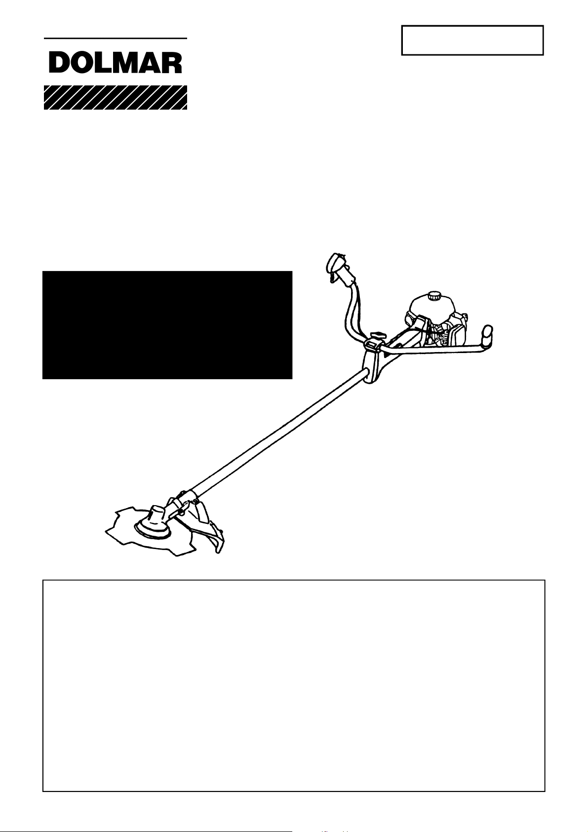
Read instruction Manual
Wear protective helmet, eye and ear
protection
WARNING / DANGER / CAUTION Top permissible tool speed
Forbidden Fuel and oil mixture
Keep distance Engine-Manual start
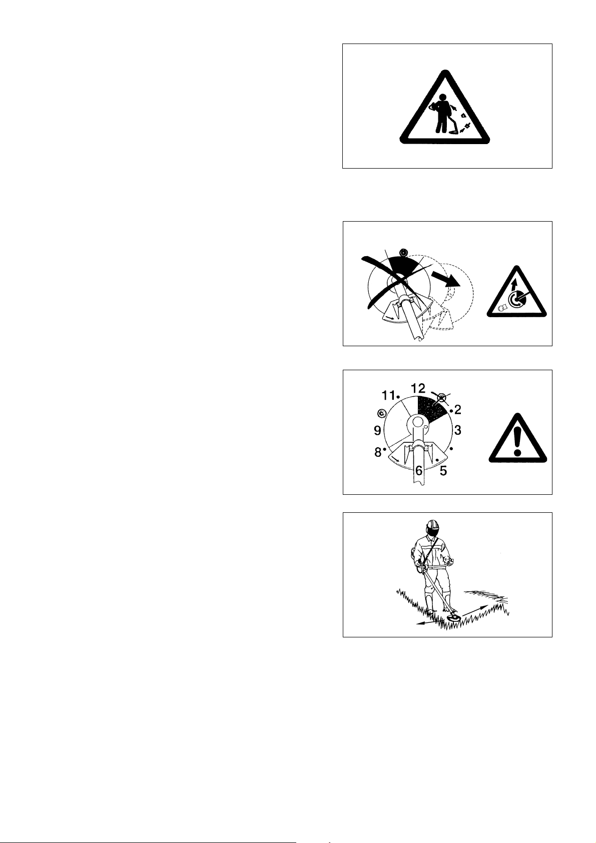
Flying object hazard Emergency stop
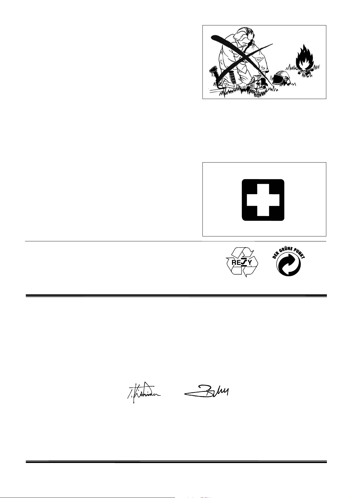
No smoking First Aid
No open flame Recycling
Protective gloves must be worn ON/START
Kickback OFF/STOP
Keep the area of operation clear of all
persons and pets
CE mark
2
SAFETY INSTRUCTIONS
General Instructions
– To ensure correct operation, the user has to read this instruction manual to
make himself familiar with the handling of the brush cutter. Users
insufficiently informed will risk danger to themselves as well as others due to
improper handling.
– It is recommended only to lend the brush cutter to people who have proven
to be experienced with brush cutters.
Always hand over the instruction manual.
– First users should ask the dealer for basic instructions to familiarize oneself
with the handling of an engine powered cutter.
– Children and young persons aged under 18 years must not be allowed to
operate the brush cutter. Persons over the age of 16 years may however
use the device for the purpose of being trained only whilst under supervision
of a qualified trainer.
– Use brush cutters with the utmost care and attention.
– Operate the brush cutter only if you are in good physical condition. Perform
all work calmly and carefully. The operator has to accept liability for others.
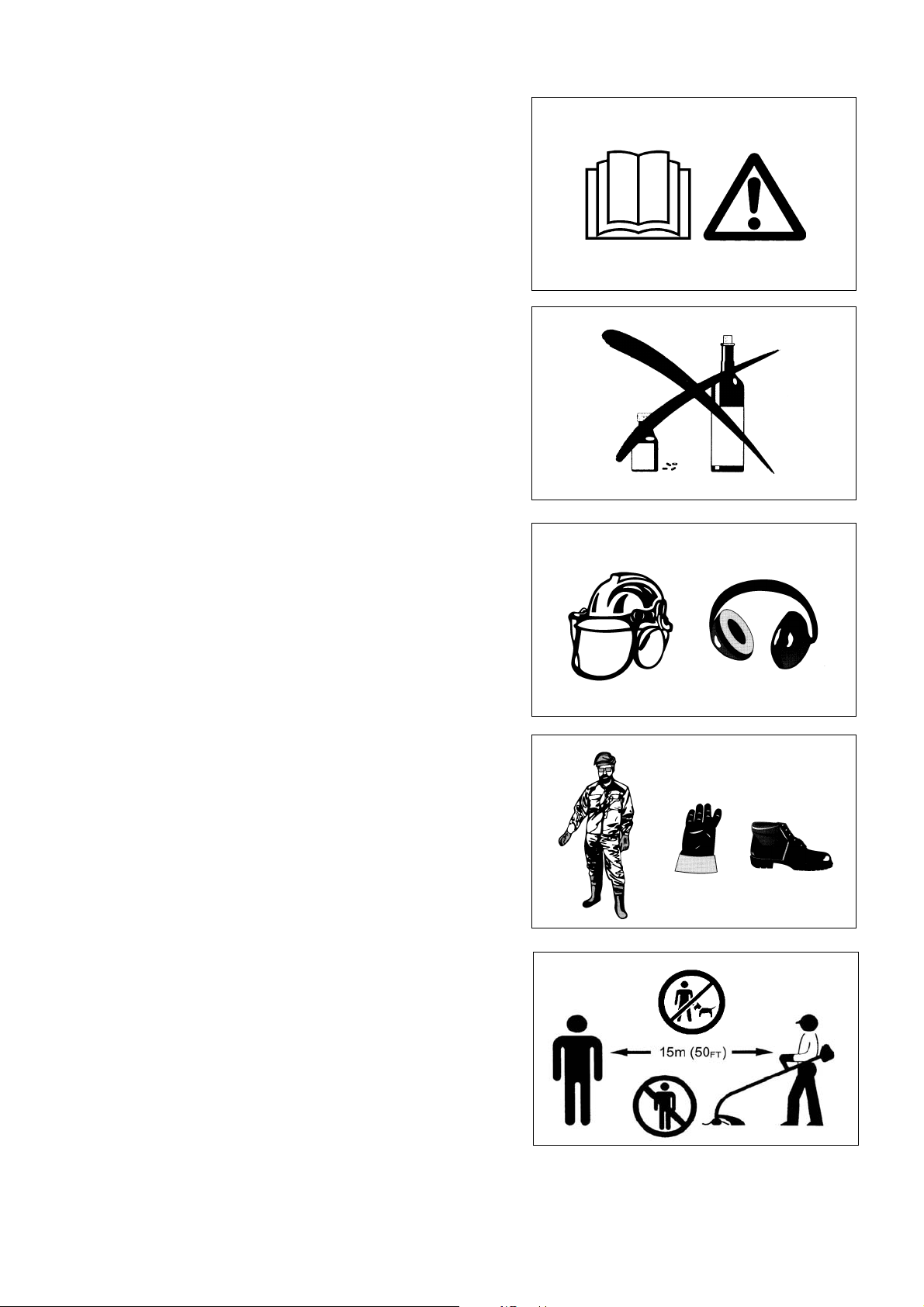
– Never use the brush cutter after consumption of alcohol or drugs, or if feeling
tired or ill.
Intended use of the machine
– The Brush Cutter is only intended for cutting grass, weeds, Bushes,
undergrowth it should not be used for any other purpose such as Edging or
hedge cutting as this may cause injury.
Personal protective equipment
– The clothing worn should be functional and appropriate, i.e. it should be
tight-fitting but not cause hindrance. Do not wear either jewelry or clothing
which could become entangled with bushes or shrubs.
– In order to avoid either head-, eye-, hand-or foot injuries as well to protect
your hearing the following protective equipment and protective clothing must
be used during operation of the brush cutter.
– Always wear a helmet where there is a risk of falling objects. The protective
helmet (1) is to be checked at regular intervals for damage and is to be
replaced at the latest after 5 years. Use only the approved protective
helmets.
– The visor (2) of the helmet (or alternatively goggles) protects the face from
flying debris and stones. During operation of the brush cutter always wear
goggles, or a visor to prevent eye injuries.
– Wear adequate noise protection equipment to avoid hearing impairment (ear
muffs (3), ear plugs etc.).
– The work overalls (4) protect against flying stones and debris.
We strongly recommend that the user wears work overalls.
– Special gloves (5) made of thick leather are part of the prescribed equipment
and must always be worn during operation of the brush cutter.
– When using the brush cutter, always wear safety shoes (6) with a non-slip
sole. This protects against injuries and ensures a good footing.
Starting up the brush cutter
– Please make sure that there are no children or other people within a working
range of 15 meters (50ft), also pay attention to any animals in the working
vicinity.
– Before use always check that the brush cutter is safe for operation:
Check the security of the cutting tool, the control lever for easy action and
check for proper functioning of the control lever lock.
Check with your dealer for adjustment if in doubt.
Rotation of the cutting tool during idling speed is not allowed. Check for
clean and dry handles and test the function of the start/stop switch.
(1)
(2)
(3)
(4)
(5) (6)
15meters
3
Start the brush cutter only in accordance with the instructions.
Do not use any other methods for starting the engine.
– Use the brush cutter and the tools only for such applications as specified.
– Only start the brush cutter engine, after the entire assembly is done.
Operation of the device is only permitted after all the appropriate accessories
are attached.
– Before starting make sure that the cutting tool has no contact with hard
objects such as branches, stones etc. as the cutting tool will revolve when
starting.
– The engine is to be switched off immediately in case of any engine problems.
– Should the cutting tool hit stones or other hard objects, immediately switch
off the engine and inspect the cutting tool.
– Inspect the cutting tool at short regular intervals for damage (detection of
hairline cracks by means of tapping-noise test).
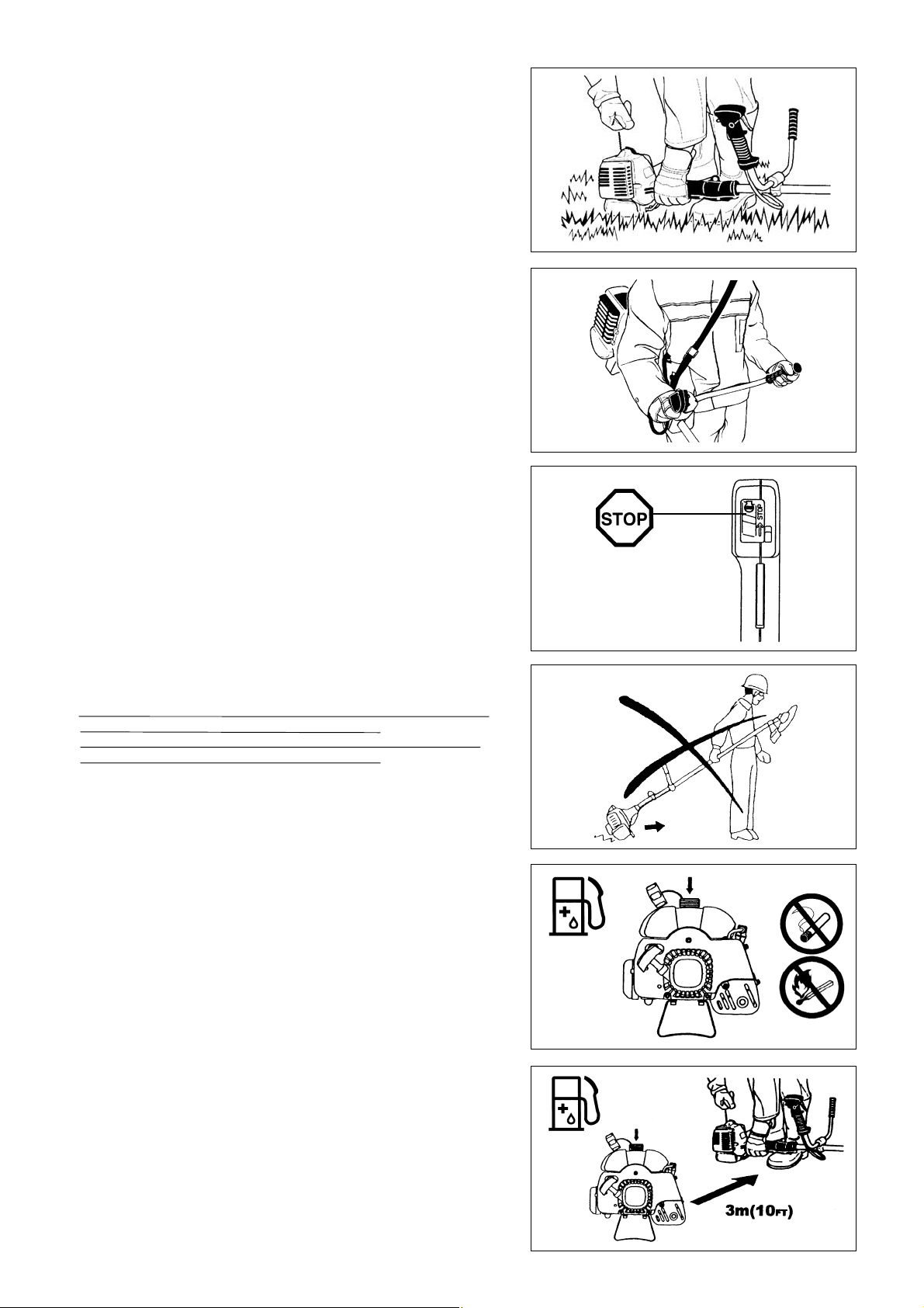
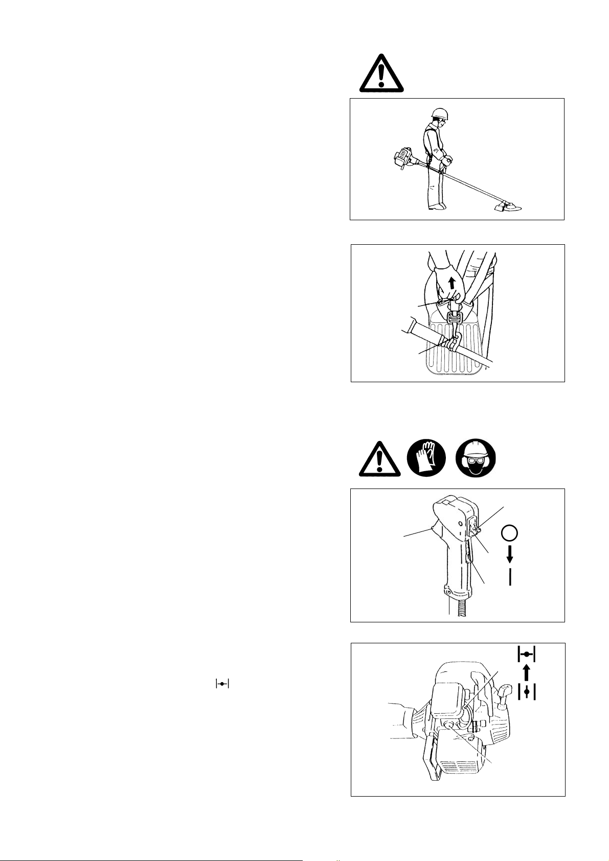
– Operate the brush cutter only with the shoulder strap attached which is to be
suitably adjusted before putting the brush cutter into operation. It is
essential to adjust the shoulder strap according to the user’s size to prevent
fatigue occurring during use. Never hold the cutter with one hand during
use.
– During operation always hold the brush cutter with both hands.
Always ensure a safe footing.
– Operate the brush cutter in such a manner as to avoid inhalation of exhaust
gas. Never run the engine in enclosed rooms (risk of gas poisoning).
Carbon monoxide is an odorless gas.
– Switch off the engine when resting and when leaving the brush cutter
unattended, and place it in a safe location to prevent danger to others or
damage to the machine.
– Never put the hot brush cutter onto dry grass or onto any combustible
materials.
– The cutting tool has to be equipped with it’s appropriate guard.
Never run the cutter without this guard.
– All protective installations and guards supplied with the machine must be
used during operation.
– Never operate the engine with faulty exhaust muffler.
– Shut off the engine during transport.
– During transport over long distances the tool protection included with the
equipment must always be used.
– Ensure safe position of the brush cutter during car transportation to avoid
fuel leakage.
– When transporting the brush cutter, ensure that the fuel tank is completely
empty.
– When unloading the Brush Cutter from the truck, never drop the Engine to
the ground or this may severely damage the fuel tank.
– Except in case of emergency, never drop or cast the Brush Cutter to the
ground or this may severely damage the Brush Cutter.
– Remember to lift the entire equipment from the ground when moving the
equipment. Dragging the fuel tank is highly dangerous and will cause
damage and leakage of fuel, possibly causing fire.
٨
Resting
٨
Transport
٨
Refuelling
٨
Maintenance
٨
Tool Replacement
Refuelling
– Shut off the engine during refuelling, keep away from open flames and do not
smoke.
– Avoid skin contact with mineral oil products. Do not inhale fuel vapor.
Always wear protective gloves during refuelling. Change and clean
protective clothing at regular intervals.
– Take care not to spill either fuel or oil in order to prevent soil contamination
(environmental protection). Clean the brush cutter immediately after fuel
has been spilt.
– Avoid any fuel contact with your clothing. Change your clothing instantly if
fuel has been spilt on it (to prevent clothing catching fire).
– Inspect the fuel cap at regular intervals making sure that it can be securely
fastened and does not leak.
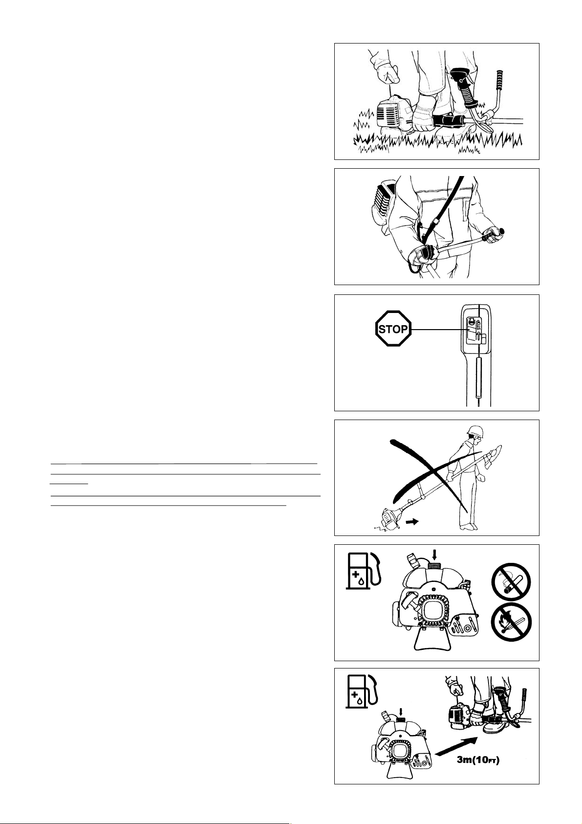
– Carefully tighten the fuel tank cap. Change location to start the engine (at
least 3 meters (10ft) away from the place of refuelling).
– Never refuel in closed rooms. Fuel vapors accumulate at ground level (risk
of explosion).
– Only transport and store fuel in approved containers. Make sure the fuel
stored is not accessible to children.
4
Method of operation
– Only use the brush cutter in good lighting and visibility. During the winter
season beware of slippery or wet areas, ice and snow (risk of slipping).
Always ensure a safe looting.
– Never cut above the shoulder height.
– Never stand on a ladder and run the brush cutter.
– Never climb up trees to perform cutting operation with the brush cutter.
– Never work on unstable surfaces.
– Remove sand, stones, nails etc. found within the working range.
Foreign particles may damage the cutting tool and can cause dangerous
kick-backs.
– Before commencing cutting, the cutting tool must have reached full working
speed.
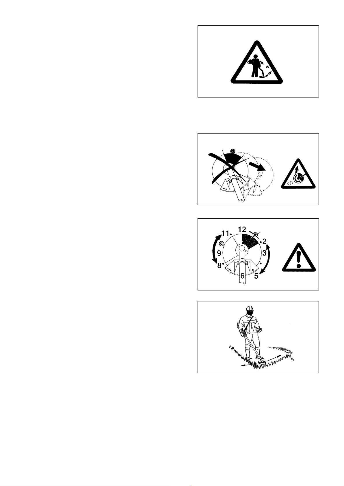
Kickback
– When operating the brush cutter, uncontrolled kickback may occur.
– This is particularly the case when attempting to cut within a blade segment
between 12 and 2 o’clock.
– Never apply the brush cutter within a segment between 12 and 2 o’clock.
– Never apply this segment of the brush cutter blade to solids, such as bushes
and trees, etc., having a diameter in excess of 3 cm or the brush cutter will
be deflected at great force with the risk of injuries.
Kickback prevention
To avoid kickbacks, observe the following:
– Operation within a blade segment between 12 and 2 o’clock presents
positive hazards, especially when using metal cutting tools.
– Cutting operations within a blade segment between 11 and 12 o’clock, and
between 2 and 5 o’clock, must only be performed by trained and experienced
operators, and then only at their own risk.
Easy cutting with almost no kickback is possible within a blade segment
between 8 and 11 o’clock.
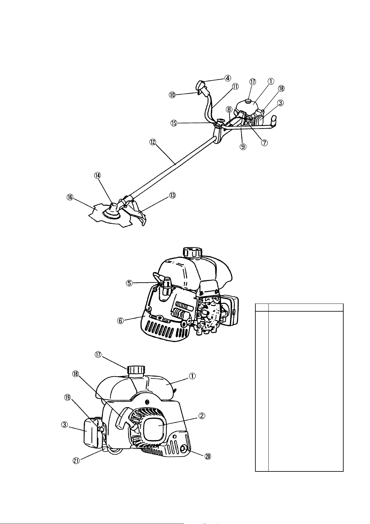
Cutting Tools
Employ only the correct cutting tool for the job in hand.
Nylon cutting head:
Exclusively designed for cutting along walls, fences, grass edges, trees, posts
etc. (supplementing the grass mower). Perform this cutting work by swinging
the grass trimmer evenly in half-circles from left to right.
Cutter blade (Star Blade (4 teeth), Eddy Blade (8 teeth), Brush Blade (3
teeth)):
For cutting thick materials, such as weed, high grass, bushes, shrubs,
underwood, thicket etc. (max. 2 cm dia. thickness). Perform this cutting work
by swinging the brush cutter evenly in half-circles from right to left (similar to
using a scythe).
Caution:
Kickback
12
Diagrammatic
figure
Diagrammatic
figure
2
Maintenance instructions
– The condition of the cutter, in particular of the cutting tool of the protective
devices and also of the shoulder strap must be checked before commencing
work. Particular attention is to be paid to the cutting blades which must be
correctly sharpened.
– Turn off the engine and remove the spark plug connector when replacing or
sharpening cutting tools, and also when cleaning the cutter or cutting tool.
5
Never straighten or weld damaged cutting tools.
– Operate the brush cutter with as little noise and contamination as possible.
In particular, check the correct setting of the carburetor.
– Clean the brush cutter at regular intervals and check that all screws and nuts
are well tightened.
– Never service or store the brush cutter in the vicinity of open flames.
– Always store the brush cutter in locked rooms and with an emptied fuel tank.
Observe the relevant accident prevention instructions issued by the relevant
trade associations and by the insurance companies.
Do not perform any modifications on the brush cutter as this will endanger your
safety.
The performance of maintenance or repair work by the user is limited to those
activities as described in the instruction manual. All the other work is to be done
by an Authorized Service Agent. Use only genuine spare parts and accessories
released and supplied by DOLMAR.
Use of non-approved accessories and tools means increased risk of accidents.
DOLMAR will not accept any liability for accidents or damage caused by the use of
non-approved cutting tools and fixing devices of cutting tools, or accessories.
First Aid
In case of accident, make sure that a first-aid box is available in the vicinity of
the cutting operations. Immediately replace any item taken from the first aid
box.
When asking for help, please give the following information:
– Place of accident
– What happened
– Number of injured persons
– Kind of injuries
– Your name
Packaging
The DOLMAR brush cutter will be delivered in two protective cardboard boxes
to prevent transport damage. Cardboard is a basic raw material and is
therefore consequently reusable or suitable for recycling (waste paper
recycling).
EC-DECLARATION OF CONFORMITY
Model; MS-4211
We declare under our sole responsibility that this product is in compliance with the following standards of standardized
documents, ISO11806, EN55012 in accordance with Council Directives, 89/392/EEC, amended 98/37/EEC, 93/68/EEC,
89/336/EEC, amended 92/31/EEC.
Measured Sound Power: 114 dB
Guarantee Sound Power: 118 dB
These sound power levels wear measured in accordance with Council Directive, 2000/14/EC.
Conformity assessment procedure: Annex V.
CE2008
Tamiro Kishima Rainer Bergfeld
Managing Director Managing Director
Responsible Manufacturer:
Makita Corporation.
3-11-8,Sumiyoshi-cho, Anjo, Aichi, JAPAN
Authorized Representative in Europe:
DOLMAR Gmbh
Jenfelder Str. 38, 22045 Hamburg, Germany
6

TECHNICAL DATA
Model
MS-4211
U handle
Dimensions : length x width x height mm
(without cutting blade)
Mass (without plastic guard and cutting blade) kg
Volume (fuel tank) L
Engine displacement cm
Maximum engine performance kw
Engine speed at recommended max. spindle speed min
Maximum spindle speed (corresponding) min
Fuel consumption kg/h
Specific fuel consumption g/kwh
Idling speed min
Clutch engagement speed min
Carburetor (Diaphragm - carburetor) type
Ignition system type
1800x620x550
7.8
0.96
3
-1
-1
40.2
1.40 at 7000 min
8500
5800
-1
0.89
635
-1
-1
2600
3600
WALBRO WYJ
Solid state ignition
Spark plug type
Electrode gap mm
Right handle
(Rear grip)
Vibration per
ISO 7916
1)
Left handle
(Front grip)
Sound pressure level average to ISO 7917
Sound power level average to ISO 10884
Idling m/s
Racing or W.O.T m/s
Idling m/s
Racing or W.O.T m/s
1)
1)
dB
dB
Mixture ratio (Gasoline : DOLMAR 2-stroke oil)
Gear ratio
2
2
2
2
NGK BPMR7A
0.6 - 0.7
2.3
1.9
2.7
1.4
91.2
109.0
25 : 1
13/19
1) The data is prepared taking equally into account the idling and racing or wide open throttle speed operating modes.
7
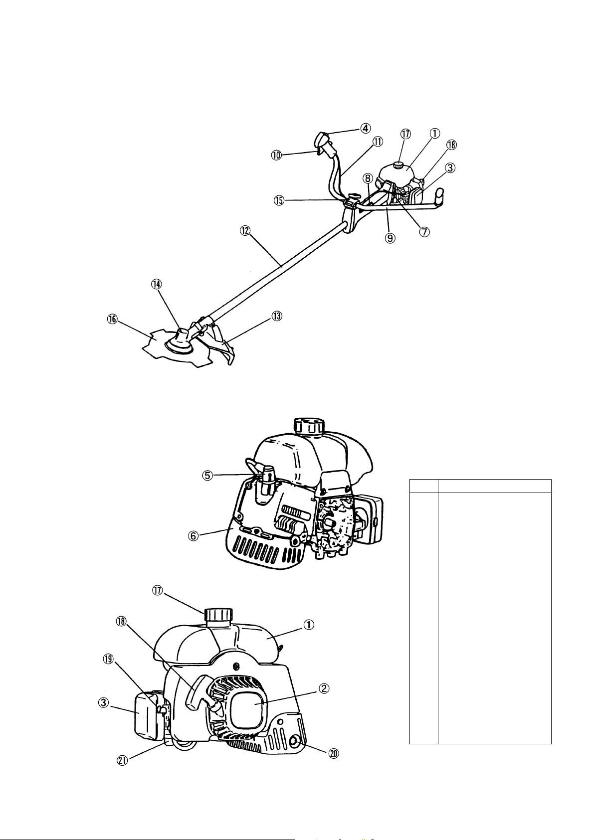
DESIGNATION OF PARTS
MS-4211
Brush Cutter
GB DESIGNATION OF PARTS
1 Fuel Tank
2 Rewind Starter
3 Air Cleaner
4 I-O Switch (on/off)
5 Spark Plug
6 Exhaust Muffler
7 Clutch Case
8 Hanger
9 Handle
10 Throttle Lever
11 Control Cable
12 Shaft
13 Protector
14 Gear Case
15 Handle Holder
16 Cutter Blade
17 Fuel Filler Cap
18 Starter Knob
19 Choke Lever
20 Exhaust Pipe
21 Primer Pump
8
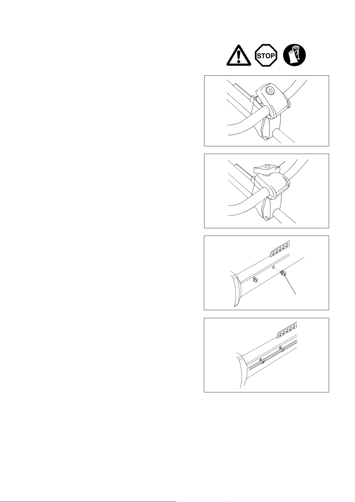
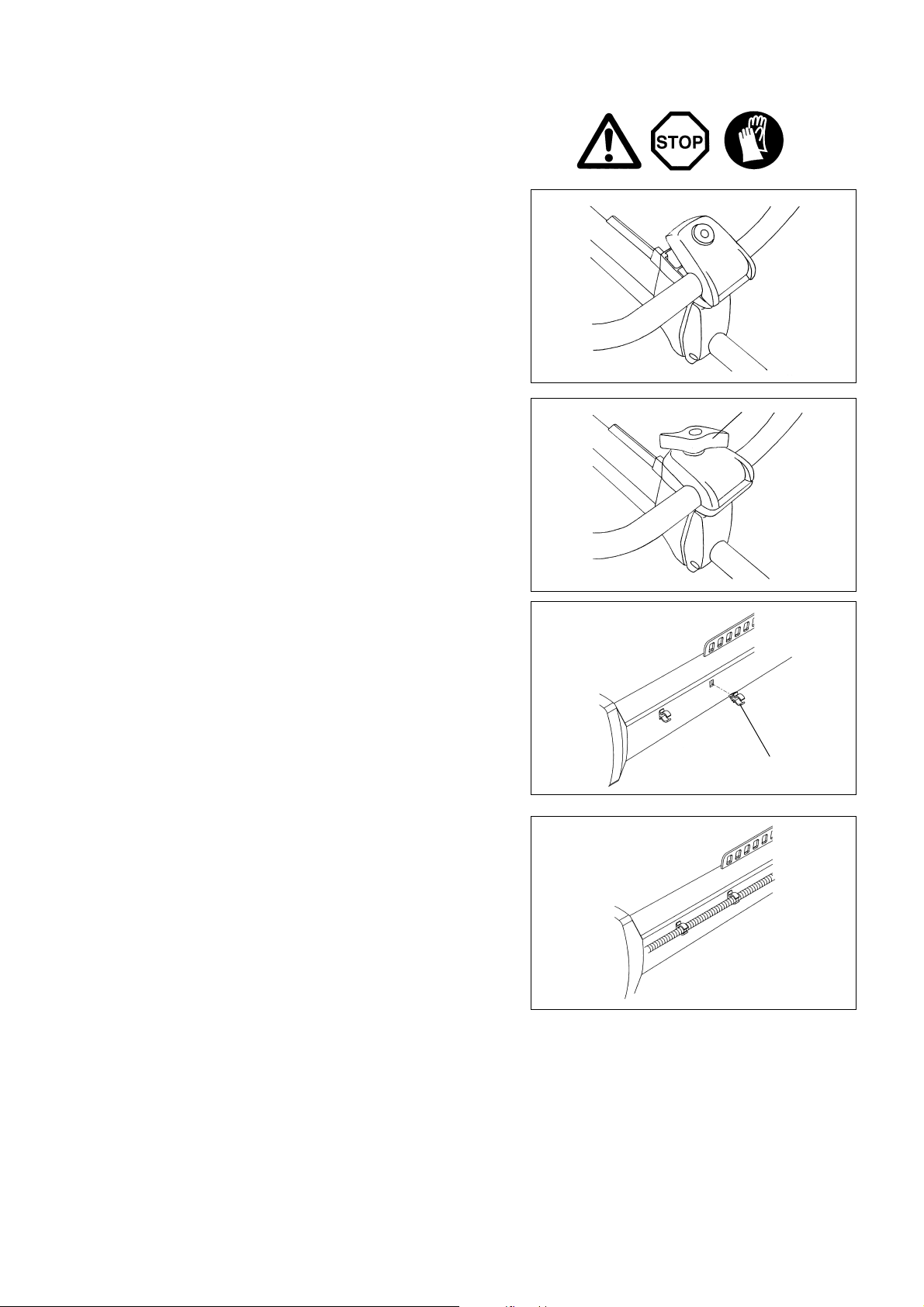
MOUNTING OF HANDLE
CAUTION: Before doing any work on the brush cutter, always stop the engine
and pull the spark plug connector off the spark plug.
Always wear protective gloves!
CAUTION: Start the brush cutter only after having assembled it completely.
– Place the handle with throttle lever on the handle holder in such a manner
that it will be on the right side (to be held by the right hand) viewed from the
engine side.
– Provisionally fix the upper side of the handle holder with the attached bolt (1).
– Adjust the handle to an angle easy to manipulate, and fix it by the bolt.
(1)
– Fix the control cable by three clips (2).
Note: If the control cable is not kept tight, it may be caught by a twig. Leading
to an accident.
Clips (2)
9
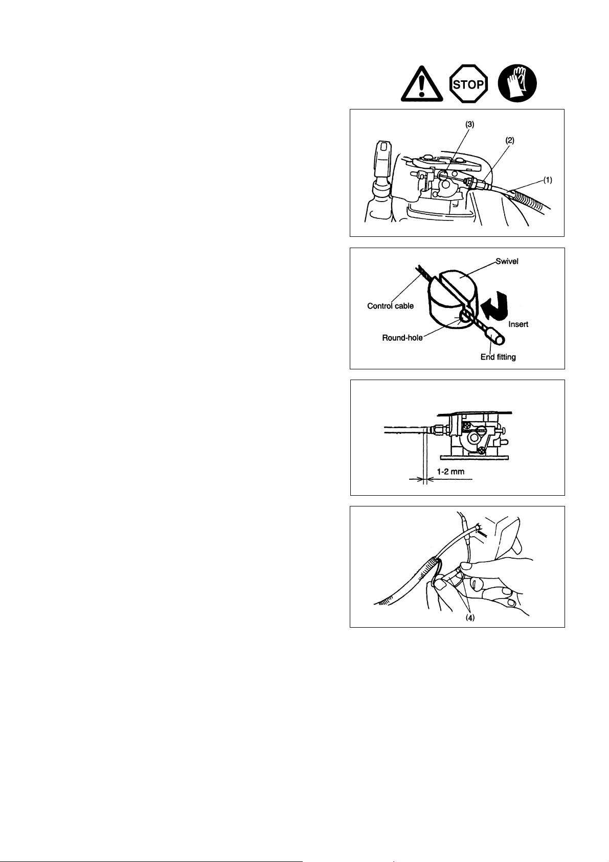
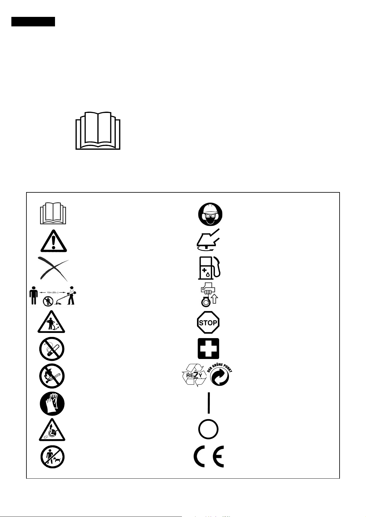
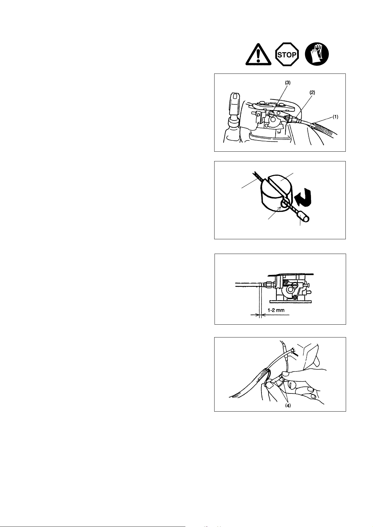
ASSEMBLY OF THROTTLE WIRE AND IGNITION WIRE
– Remove the air cleaner cover.
– Place the control cable (1) in the adjusting bolt (2), and shift the swivel (3) so
that the cable will be put in the swivel groove. At this time, the round-hole
side of the swivel will be oriented toward the inner wire end-metal fitting.
– Release the swivel, and confirm that the inner wire-end metal fitting will be
placed in the hole.
– Mount the air cleaner cover.
Adjust the control cable by adjusting bolt so that it will have 1 to 2 mm play
when the throttle lever is set to the low-speed position by carburetor adjusting
bolt. (Be careful that the cutter blade will not turn in idling.)
– Connect the female and male bullet connectors (4) from throttle assembly to
the male and female bullet connectors coming from engine.
– Install the air cleaner cover.
10
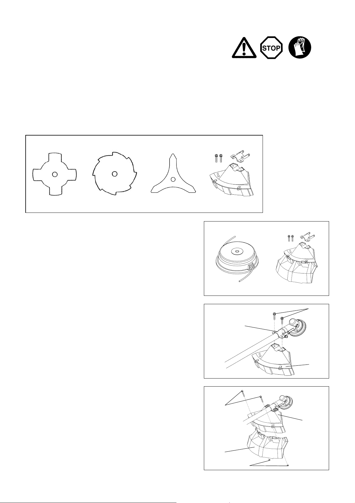
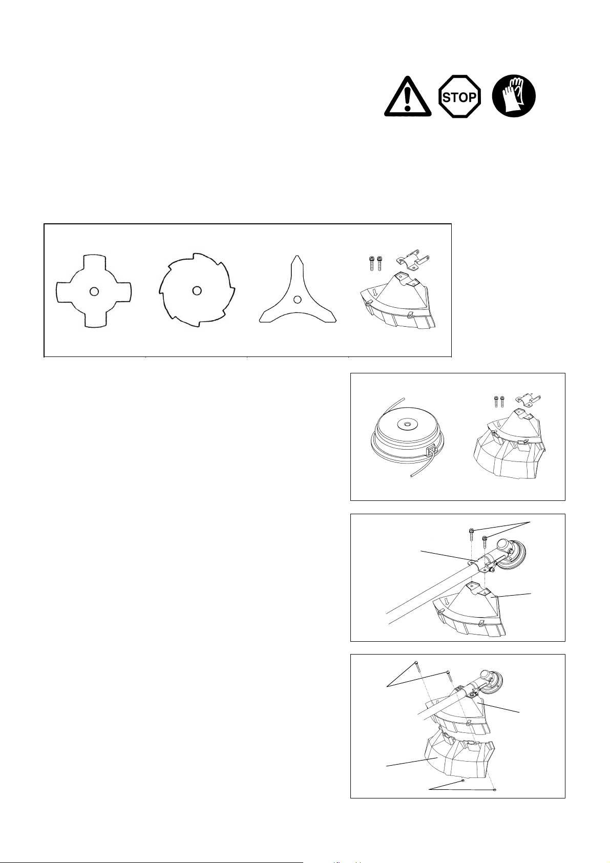
MOUNTING OF PROTECTOR
To meet the applicable safety provisions, only the tool/protector combinations
as indicated in the table must be used.
Be sure to use genuine DOLMAR cutter blades or nylon cutting
head.
– The cutter blade must be well polished, free of cracks or breakage. If the cutter blade hits against a stone during operation, stop the engine
and check the blade immediately.
– Polish or replace the cutter blade every three hours of operation.
– The outside diameter of the cutter blade must be 255mm (10-1/32”). Never use any blades surpassing 255mm (10-1/32”) in outside
diameter.
– If the nylon cutting head hits against a stone during operation, stop the engine and check the nylon cutting head immediately.
– The mounting hole for the cutter blade is 25.4mm (1").
Star Blade Eddy Blade Brush Blade Protector for metal blades
PART NO. 6418501400 PART NO. 6418501900 PART NO. 6418502200 PART NO. 6348002000
CAUTION: The appropriate protector must always be installed, for your own
safety and in order to comply with accident-prevention regulations.
Operation of the equipment without the guard being in place is not
permitted.
– Fix the protector (1) to the clamp (3) with two bolts M6 x 30 (2).
NOTE: Tighten the right and left bolts evenly so that the gap between the
clamp (3) and the protector (1) will be constant.
Otherwise, the protector sometimes may not function as specified.
Nylon cutting head Protector for cord cutter
PART NO.6458009001 PART NO.6348001000
(3)
(2)
(1)
– In use of the nylon cutting head insert the protector (6) into the protector (1),
and fasten them with two screw (4) and two nuts (5).
11
(4)
(1)
(6)
(5)
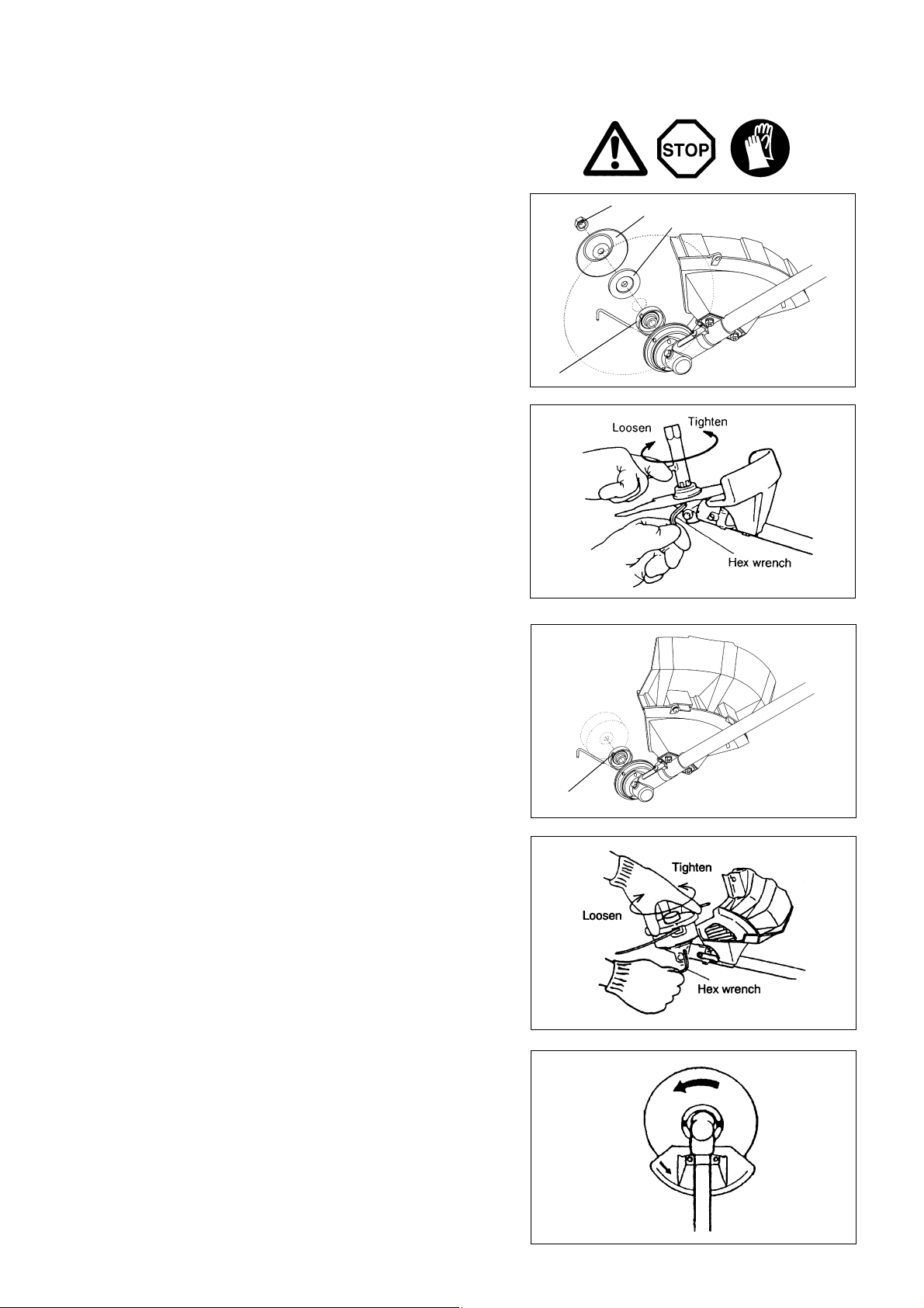
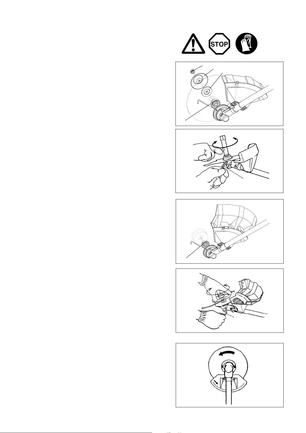
MOUNTING OF CUTTER BLADE OR NYLON CUTTING HEAD
Turn the machine upside down, and you can replace the cutter blade or the
nylon cutting head easily.
– Insert the hex wrench through the hole in the gear case and rotate the
receiver washer (4) until it is locked with the hex wrench.
– Loosen the nut (1) (left-hand thread) with the socket wrench and remove the
nut (1), cup (2), and clamp washer (3).
Mounting of cutter blade
With the hex wrench still in place.
– Mount the cutter blade onto the shaft so that the guide of the receiver washer
(4) fits in the arbor hole in the cutter blade. Install the clamp washer (3),
cup (2), and secure the cutter blade with the nut (1).
[Tightening torque: 13 - 23 Nm]
NOTE: Always wear gloves when handling the cutter blade.
NOTE: The cutter blade-fastening nut (with coned disc spring) is a consumable
part.
If there appears any wear or deformation on the coned disc spring,
replace the nut.
Mounting of nylon cutting head
– The clamp washer (3), cup (2), and nut (1) are not necessary for mounting
the nylon cutting head. The nylon head should go on top of the receiver
washer (4).
– Insert the hex wrench through the hole in the gear case and rotate the
receiver washer (4) until it is locked with the hex wrench.
(4)
(1)
(2)
(3)
– Then screw the nylon cutting head onto the shaft by turning it
counter-clockwise.
– Remove the socket-head wrench.
– Make sure that the blade is the left way up.
(4)
Rotation
12
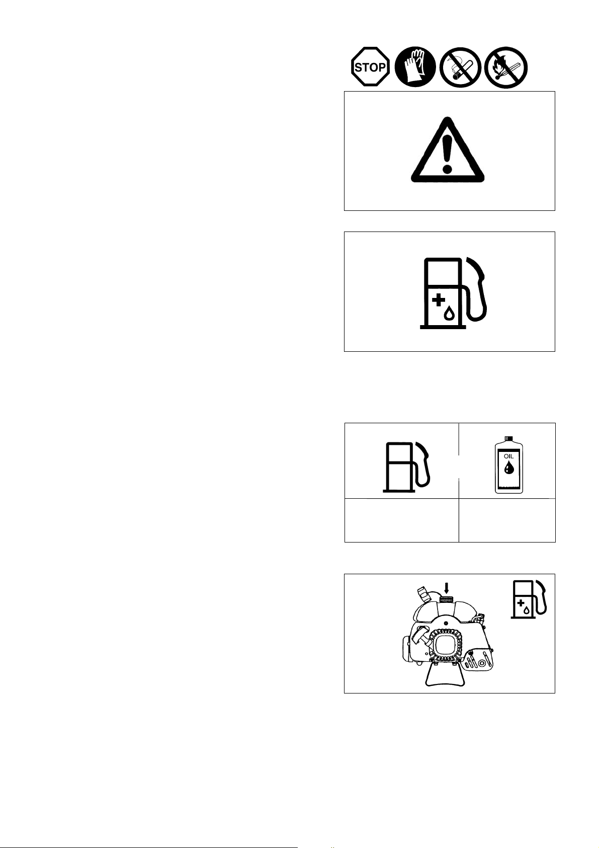
FUELS/REFUELING
Handling fuel
Utmost care is required when handling fuel. Fuel may contain substances
similar to solvents. Refuel either in a well ventilated room or outdoors. Do
not inhale fuel vapors, avoid any contact of fuel or oil with your skin.
Mineral oil products degrease your skin. If your skin comes in contact with
these substances repeatedly and for an extended period of time, it will
desiccate. Various skin diseases may result. In addition, allergic reactions
may occur. Eyes can be irritated by contact with oil. If oil comes into your
eyes, immediately wash them with clear water. If your eyes are still irritated,
see a doctor immediately.
Fuel and oil mixture
The engine of the brush cutter is a high-efficiency two-stroke engine. It is run
with a mixture of fuel and two-stroke engine oil. The engine is designed for
unleaded regular fuel with a min. octane value of 91 RON. In case no such
fuel is available, you can use fuel with a higher octane value. This will not
affect the engine, but may cause poor operating behaviour.
A similar situation will arise from the use of leaded fuel. To obtain optimum
engine operation and to protect your health and the environment, only unleaded
fuel should be used!
For lubricating the engine use a two-stroke engine oil (quality grade: TC-3),
which is added to the fuel. The engine has been designed for use with
specified two-stroke engine oil and a mixture ratio of only 25:1 to protect the
environment. In addition, a long service life and a reliable operation with a
minimum emission of exhaust gases is guaranteed. It is absolutely essential
to observe a mixture ratio of 25:1 (specified 2-stroke engine oil), as otherwise
reliable function of the brush cutter cannot be guaranteed.
Observe the Safety Instructions on page 4.
The correct mixture ratio:
Mix 25 parts gasoline with 1 part specified 2-stroke engine oil (see table on
right).
NOTE: For preparing the fuel-oil mixture first mix the entire oil quantity with half
of the fuel required, then add the remaining fuel. Thoroughly shake
the mixture before filling it into the brush cutter tank. It is not wise to
add more engine oil than specified to ensure safe operation.
This will only result in a higher production of combustion residues which
will pollute the environment and clog the exhaust channel in the
cylinder as well as the muffler. In addition, the fuel consumption will
rise and the performance will decrease.
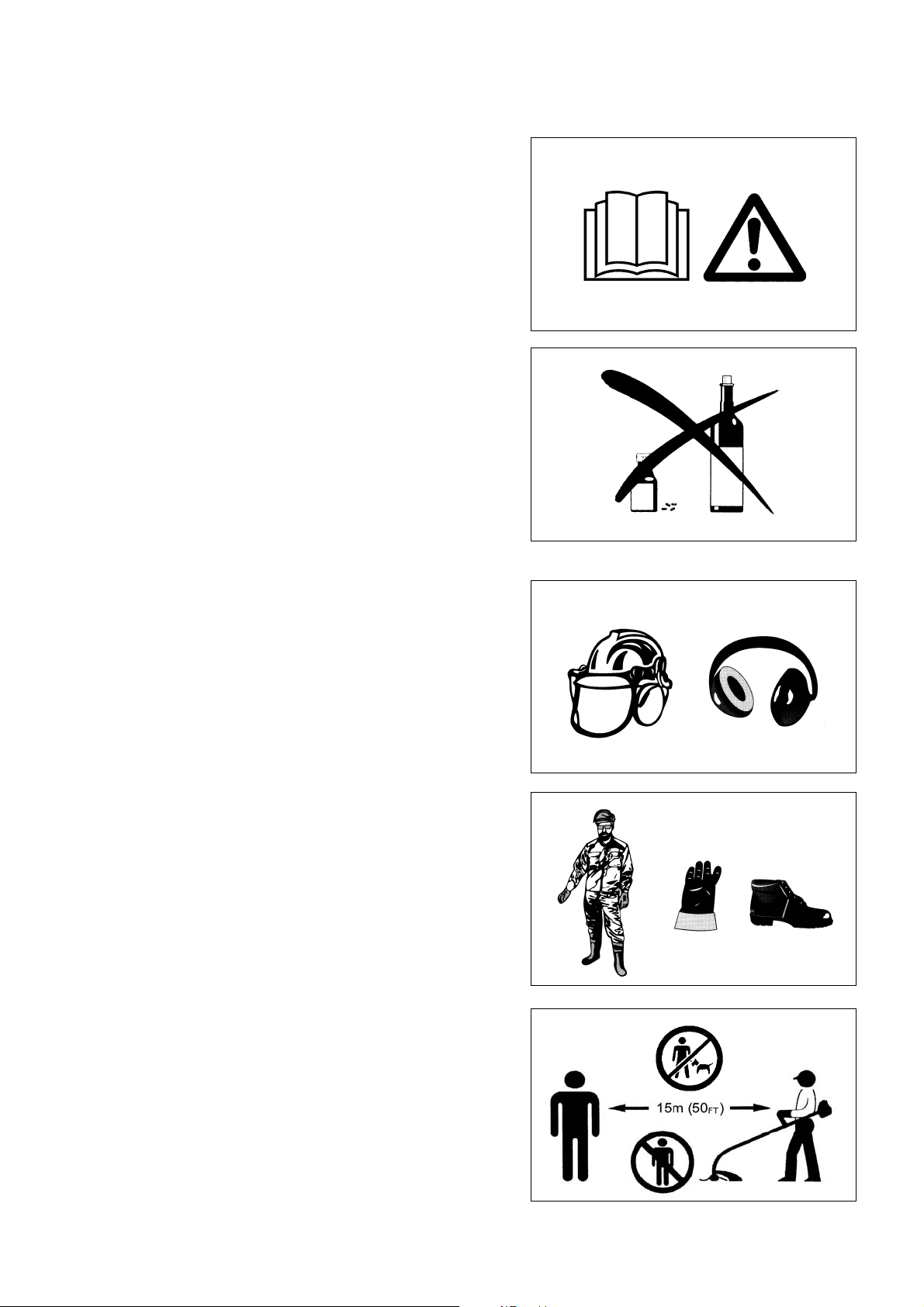
The engine must be switched off.
– Thoroughly clean the area around the fuel filler cap, to prevent dirt from
getting into the fuel tank.
– Unscrew the fuel filler cap and fill the tank with fuel.
– Tightly screw on the fuel filler cap.
– Clean screw fuel filler cap and tank after refueling.
Storage of Fuel
Fuel cannot be stored for an unlimited period of time.
Purchase only the quantity required for a 4 week operating period. Only use
approved fuel storage containers.
Gasoline 25:1
㧗
㧗
25
1000 mL (1 L) 40 mL
5000 mL (5 L) 200 mL
10000 mL (10 L) 400 mL
㧗㧗
1
13
CORRECT HANDLING OF MACHINE
Attachment of shoulder strap
– Wear shoulder strap across the chest. Keep machine at your right.
– Adjust the strap length so that the cutter blade will be kept parallel with the
ground.
Detachment
– In case of emergency, remove the emergency detachment lever (1) by
pulling strongly with a finger. The machine sill detach from body.
Be extremely careful to maintain control of the machine at this time. Do not
allow the machine to be deflected toward you or anyone in the work vicinity.
WARNING: Failure to maintain complete control of the machine at all could
result in serious bodily injury or DEATH.
(1)
PUTTING INTO OPERATION
Observe the applicable accident prevention regulations.
Starting
Move at least 3m (10ft) away from the place of refueling. Place the brush
cutter on a clean piece of ground taking care that the cutting tool does not
come into contact with the ground or any other objects.
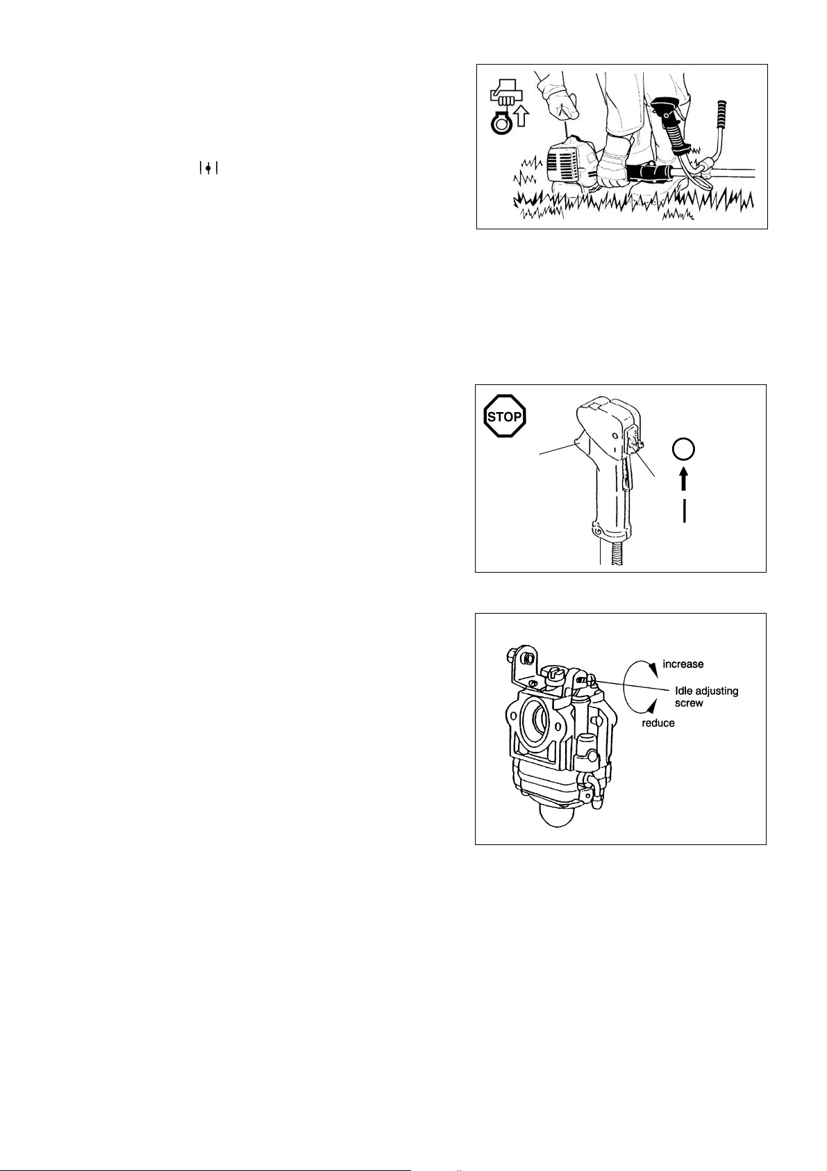
Cold start
– Push the I-O switch (1) in the direction shown by the arrow.
– Grasp the handle (hand pressure activates the safety lock-off lever (2)).
– Press the control lever (3) and hold it down.
– Press the lock button (4) and release the control lever, and then release the
lock button (the lock button holds the control lever in the start-up position).
– First place the machine on the ground.
– Give a gentle push on the primer pump (5) repeatedly (7-10 times) until fuel
comes into the primer pump.
– Move the choke lever (6) to the top position ( ).
Hanger
(4)
(3)
(1)
(2)
(6)
14
(5)
– Firmly hold the clutch case by your left hand, as illustrated.
– Slowly pull the starter grip until resistance is felt and continue with a smart
pull.
– Do not pull out the starter rope to its full extent and do not allow the starter
handle to be retracted without control, but ensure that it is retracted slowly.
– Repeat the starting operation until initial ignitions are heard.
– Depress the choke lever ( ) and pull the starter rope again until the
engine starts.
– As soon as the engine starts, immediately tap and release the throttle, thus
releasing the half-throttle lock so that the engine can run in idle.
– Run the engine for approximately one minute at a moderate speed before
applying full throttle.
Caution during operation:
If the control lever is opened fully in a no-load operation, the engine rotation is increased to 10,000 min
a higher speed than required and at an approximate speed of 6,000 - 8,000 min
-1
.
Starting the warm engine
– Same as above, except without moving the choke lever (choke lever remains
in the down position).
Stopping
– Release the control lever (3) fully, and when the engine rpm has lowered,
push the I-O switch (1) to “O” position the engine will now stop.
(3)
-1
or more. Never operate the engine at
IDLE ADJUSTMENT
– Never attempt to make engine adjustments while the unit is running and
strapped to the operator. Always make engine adjustments with the unit
resting on a flat, clear surface.
The cutter blade or the nylon cutting head should not run when the control lever
is fully released. If necessary, adjust the idle rpm using the idle adjusting
screw.
Checking the Idle speed
– Idle speed should be set to 2,600 min
If necessary correct it by means of the idle adjustment screw (the blade or
the nylon cutting head must not turn when the engine is on idle.)
Turning in the screw clockwise will cause an increase in the engine speed,
whereas turning the screw counterclockwise will reduce the engine speed.
-1
.
(1)
15
RESHARPENING THE CUTTING TOOL
CAUTION: The cutting tools mentioned below must only be resharpened by an
authorized facility. Manual resharpening will result in imbalances
of the cutting tool causing vibrations and damage to the equipment.
– cutter blade (star blade (4 teeth), eddy blade (8 teeth), brush blade(3 teeth))
An expert resharpening and balancing service is provided by Authorized
Service Agents.
NOTE: To increase the service life of the cutter blade (star blade, eddy blade)
it may be turned over once, until both cutting edges have become blunt.
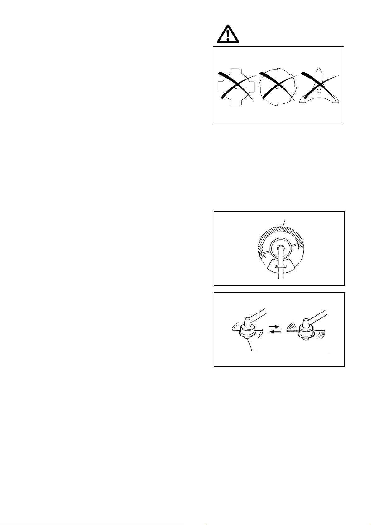
NYLON CUTTING HEAD
The nylon cutting head is a dual string trimmer head capable of both automatic and bump & feed mechanisms.
The nylon cutting head will automatically feed out the proper length of nylon cord by the changes in centrifugal force caused by increasing or
decreasing RPMS. However, to cut soft grass more efficiently, bump the nylon cutting head against the ground to feed out extra cord as
indicated under operation section.
Operation
– Increase the nylon cutting head speed to approx. 6,000 min
Low speed (under 4,800 min
properly at low speed.
– The most effective cutting area is shown by the shaded area.
-1
) is not suitable, the nylon cord will not feed out
-1
.
Most effective cutting area
If the nylon cord does not feed out automatically, proceed as follows:
1. Release the control lever to run the engine idle and then squeeze the control
lever fully. Repeat this procedure until the nylon cord feeds out to the
proper length.
2. If the nylon cord is too short to feed out automatically with the above
procedure, bump the knob of the nylon cutting head against the ground to
feed out the nylon cord.
3. If the nylon cord does not feed out with procedure 2, rewind/replace the
nylon cord by following the procedures described under “Replacing the nylon
cord”.
Idle speed Full speed
Knob
16
SERVICING INSTRUCTIONS
CAUTION: Before doing any work on the brush cutter, always switch off the
motor and pull the plug cap off the spark plug (see “checking the
spark plug”).
Always wear protective gloves.
To ensure a long service life and to avoid any damage to the equipment, the
following servicing operations should be performed at regular intervals.
Daily checkup and maintenance
– Before operation, check the machine for loose screws or missing parts. Pay
particular attention to the tightness of the cutter blade or nylon cutting head.
– Before operation, always check for clogging of the cooling air passage and
the cylinder fins.
Clean them if necessary.
– Perform the following work daily after use:
• Clean the brush cutter externally and inspect for damage.
• Clean the air filter. When working under extremely dusty conditions, clean
the filter the several time a day.
• Check the blade or the nylon cutting head for damage and make sure it is
firmly mounted.
• Check that there is sufficient difference between idling and engagement
speed to ensure that the cutting tool is at a standstill while the engine is
idling (if necessary, reduce idling speed).
• If under idling conditions the tool should still continue to run, consult your
nearest Authorized Service Agent.
– Check the functioning of the I-O switch, the lock-off lever, the control lever,
and the look button.
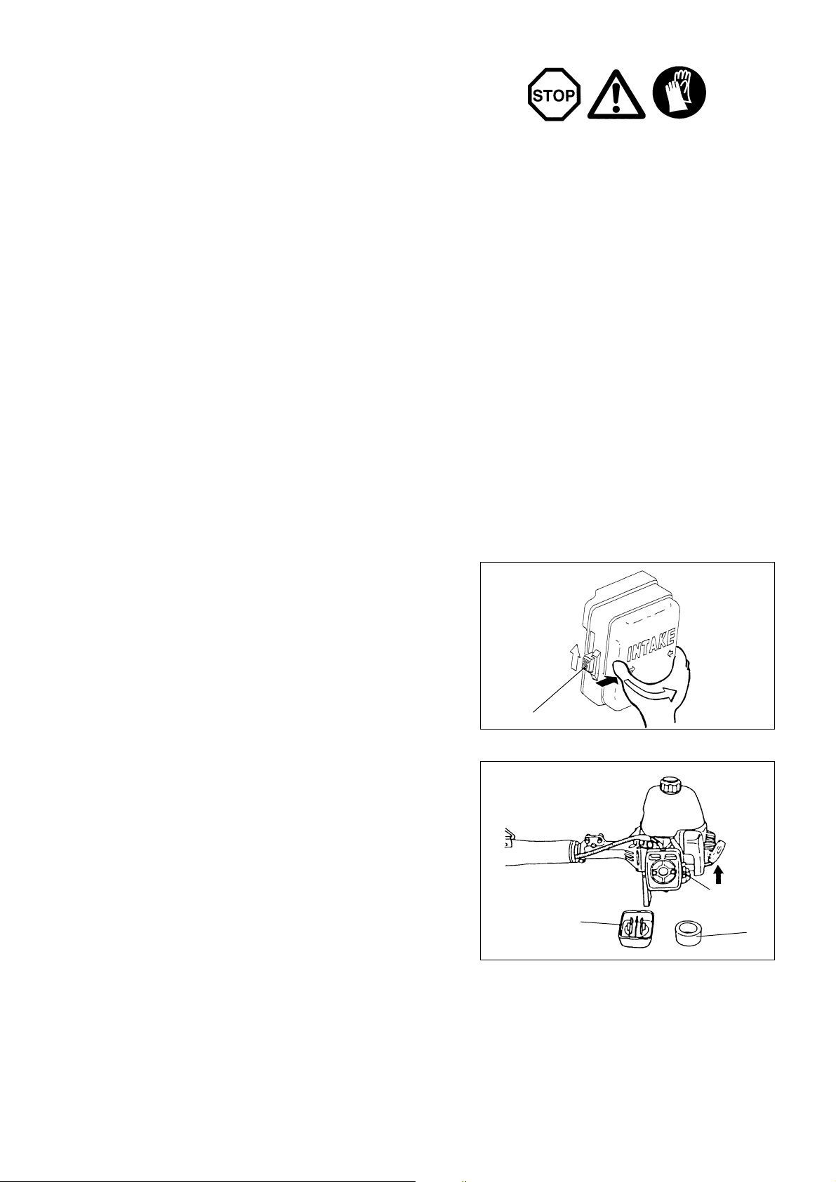
Cleaning of air cleaner
– Raise the lock lever (1) of the air cleaner cover and release the lock.
– Hold the right and left sides of the air cleaner cover, press it to the inside and
then remove it.
– Push the choke lever (2) up (arrow), to prevent dirt particles from entering the
carburetor.
– Remove the sponge element (3).
Wash it with lukewarm water and then dry it thoroughly.
– After cleaning, put back the sponge element and install the air cleaner cover
(4) and tighten the screw to secure.
NOTE: If there is excessive dust or dirt adhering to the air cleaner, clean it
every day. A clogged air cleaner may make it difficult or impossible to
start or run the engine at proper rotational speeds.
(1)
(2)
(4)
(3)
17
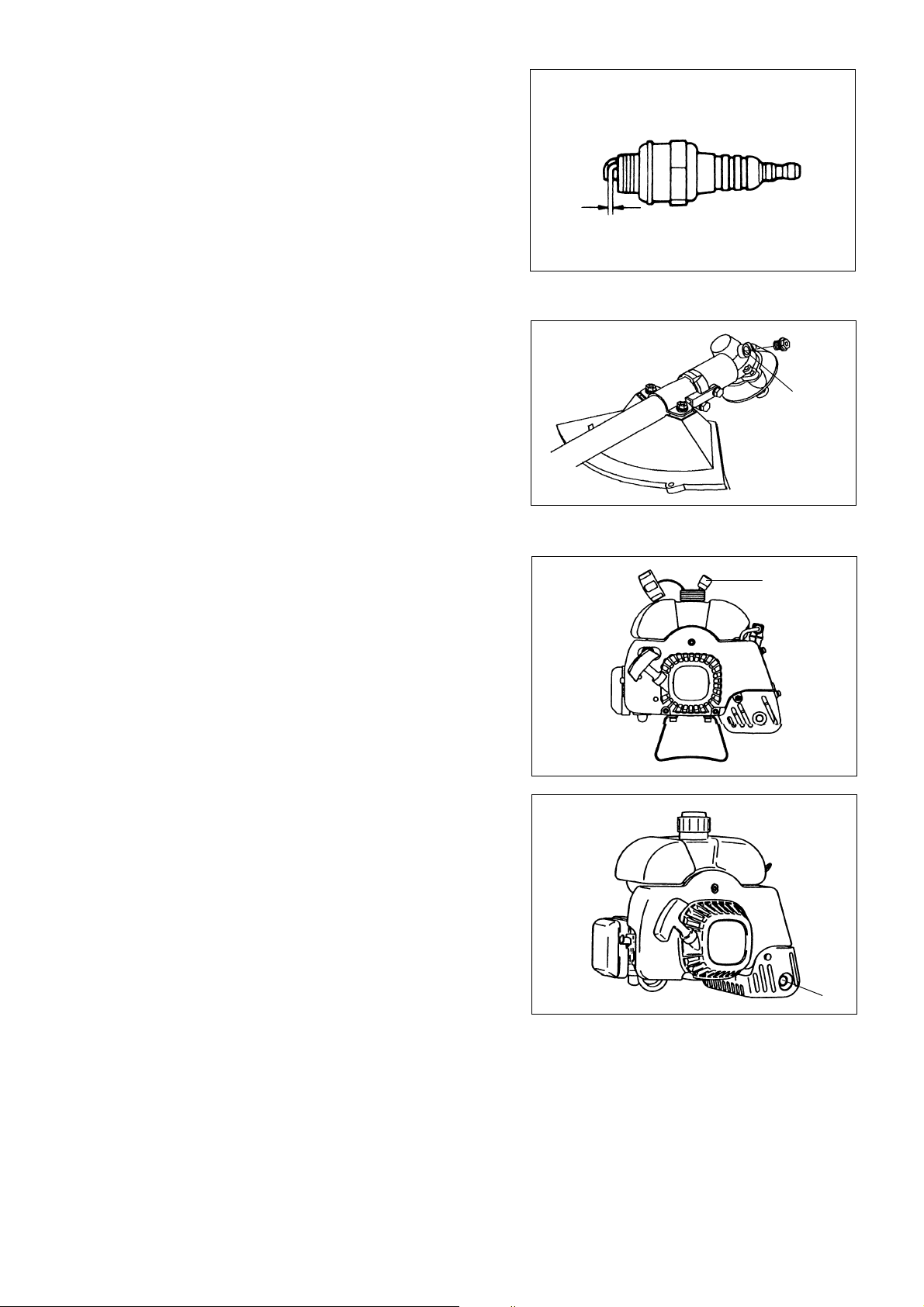
Checking the spark plug
– Only use the supplied universal wrench to remove or to install the spark plug.
– The gap between the two electrodes of the spark plug should be 0.6 - 0.7mm
(0.024" - 0.028"). If the gap is too wide or too narrow, adjust it. If the spark
plug is clogged with carbon or fouled, clean it thoroughly or replace it.
CAUTION: Never touch the spark plug connector while the engine is running
(danger of high voltage electric shock).
Supply of grease to gear case
– Supply grease (Shell Alvania 3 or equivalent) to the gear case through the
grease hole every 30 hours. (Genuine DOLMAR grease may be purchased
from your DOLMAR dealer.)
0.6 - 0.7mm
(0.024" - 0.028")
Grease hole
Suction head in the fuel tank
– The felt filler (5) of the suction head is used to filler the fuel required by the
carburetor.
– A periodical visual inspection of the felt filler is to be conducted. For that
purpose open the tank cap, use a wire hook and pull out the suction head
through the tank opening. Filters found to have hardened, been polluted or
clogged up are to be replaced.
– Insufficient fuel supply can result in the admissible maximum speed being
exceeded. It is therefore important to replace the felt filler at least quarterly
to ensure satisfactory fuel supply to the carburetor.
Cleaning of muffler exhaust port
– Check of muffler exhaust port (6) regularly.
– If it is clogged by carbon deposits, carefully scratch the deposits out with a
suitable tool.
Any maintenance of adjustment work that is not included and described in this
manual is only to be performed by Authorized Service Agents.
(5)
(6)
18

STORAGE
– When keeping the machine in storage for a long time, drain fuel from the fuel
tank and carburetor, as follows: Drain all fuel from the fuel tank. Dispose of
properly and in accordance with all local laws.
– Remove the spark plug and add a few drops of oil into the spark plug hole.
Then, pull the starter gently, so that oil covers the engine inside and tighten
the spark plug.
– Clear dirt or dust from the cutter blade and outside of engine, wipe them with
a oil-immersed cloth and keep the machine in a place as dry as possible.
Maintenance schedule
Drain fuel
Humidity
General Engine assembly, screws and
After each refuelling Control lever
Daily Air filter
Weekly Spark plug
Quarterly Suction head
Shuting down procedure Fuel tank
Fault location
Fault System Observation Cause
Engine not starting or with
difficulty
nuts
I-O switch
Cooling air duct
Cutting tool
Idling speed
Muffler
Fuel tank
Carburetor
Ignition system Ignition spark O.K. Fault in fuel supply or compression system, mechanical
Visual inspection for damage and tightness
Check for general condition and security
Functional check
Functional check
To be cleaned
To be Cleaned
Check for damage and sharpness
Inspection (cutting tool must not move)
Inspection, replace if necessary
Check and if necessary clean the opening
To be replaced
To be cleaned
Empty fuel tank
Operate until engine runs out of fuel
defect
No ignition spark I-O switch operated, wiring fault or short circuit, spark
Fuel supply Fuel tank filled Incorrect choke position, carburetor defective, fuel
Compression No compression when
Mechanical fault Starter not engaging Broken starter spring, broken parts inside of the engine
Warm start problems Tank filled ignition spark
Engine starts but dies
immediately
Fuel tank vent defective, fuel supply line interrupted,
Insufficient performance Several systems
Fuel supply Tank filled Incorrect idling adjustment, carburetor contaminated
may simultaneously
be affected
pulled over
existing
Engine idling poor Air filter contaminated, carburetor contaminated, muffler
plug or connector defective, ignition module faulty
supply line bent or blocked, fuel dirty.
Cylinder bottom gasket defective, crankshaft seals
damaged, cylinder or piston rings defective or improper
sealing of spark plug
Carburetor contaminated, must be cleaned
cable or I-O switch faulty
clogged, exhaust duct in the cylinder clogged
19
French
Nous vous remercions d'avoir fait l'acquisition de la débroussailleuse
DOLMAR. Nous sommes heureux de pouvoir vous conseiller la
débroussailleuse DOLMAR qui représente le résultat d'un long programme
de développement et de plusieurs années de recherche et d'expérience.
Veuillez lire cette brochure qui fait référence en détail aux différents points
témoignant de l'efficacité exceptionnelle de votre débroussaileuse
DOLMAR.
Table des matières Page
Symboles................................................................... 20
Consignes de sécurité...........................................21-24
Caractéristiques techniques....................................... 25
Nomenclature des pièces...........................................26
Montage de la poignée...............................................27
Assemblage du câble de commande et
du câble d’allumage...................................................28
Montage du dispositif de protection............................29
Montage de la lame de coupe ou de la tête
de coupe à fil .............................................................30
Carburant/Ravitaillement............................................31
Manipulation correct de la machine............................32
Mise en marche ....................................................32-33
Ajustement en marche à vide.....................................33
Réaffütage de l'outil de coupe.................................... 34
Tête de coupe à fil .....................................................34
Instructions relatives aux réparations....................35-36
Remisage...................................................................37
SYMBOLES
Vous rencontrerez les symboles suivants en parcourant le manuel d'instructions.
Lire le manuel d'instructions
Porter un casque de protection, des
protections visuelles et auditives
Avertissement/Danger/Précautión
Interdit Mélange de carburant et d'huile
Maintenir ses distances Démarrage manuel de la machine
Risque de projections d'objets Arrêt d'urgence
Interdit de fumer Premier secours
Flammes vives interdites Recyclage
Porter des gants de protection On/Démarrage
Vitesse maximale autoriseé de l’outil de
coupe
Rejet Off/Arrêt
Maintenir toute personne et tout
animal domestique à l'écart de la zone
de travail
Logo de la CE
㩷
20
CONSIGNES DE SÉCURITÉ
Instructions générales
– Pour utiliser la machine correctement, I’utilisateur doit lire ce manuel
d’instructions afin de se familiariser avec la manipulation de la
débroussailleuse. Les utilisateurs disposant d’informations insuffisantes
risquent de mettre leur propre vie comme celle de ticrs en danger en
manipulant la machine de facon incorrecte.
– Il est conseillé de prêter la débroussailleuse uniquement à des personnes
ayant fait leurs preuvés dans la manipulation de débroussailleuses.
Toujours leur remettre le manuel d’instructions.
– Les premiers utilisateurs devraient demander au concessionnaire de leur
dispenser les instructions de base afin de se familiariser à la manipulation de
débroussailleuses propulsées par moteur.
– Les enfants et les jeunes gens de moins de 18 ans ne sont pas autorisés à
utiliser la débroussailleuse. Cependant, les jeunes gens âgés de plus de 16
ans peuvent utiliser la machine pour s'entraîner, mais uniquement sous la
surveillance d'un formateur qualifié.
– Utiliser les débroussailleuses avec le plus de soin et d'attention possibles.
– Utilisez la débroussailleuse uniquement si vous être en bonne condition
physique.
Procédez aux travaux avec calme et attention. L’utilisateur est responsible
vis à vis des autres personnes.
– Ne jamais utiliser la débroussailleuse après absorption d'alcool ou de
médicaments ou si l'on se sent fatiqué ou souffrant.
Utilisation spéciale de la machine
– La débroussailleuse est seulement pour couper l’herbes, broussailles et en
sous-bois. Ne jamais employer la machine pour les usages comprenant
tailles de bordure et de haies qui pourrait pouvaient causer des blessures.
㩷
Équipement personnel de protection
– Les habits doivent être fonctionnels et adaptés, c'est-à-dire qu'ils doivent être
serrés sans toutefois entraver les mouvements. Ne pas porter de bijoux ou
d'habits qui pourraient s'accrocher dans les buissons ou les broussailles.
– Porter l'équipement et les habits de protection lors de l'utilisation de la
débroussailleuse afin d'éviter les blessures au niveau de la tête, des yeux,
des mains ou des pieds.
– Toujours porter un casque dans les endroits où les chutes d'objets sont
possibles. Vérifier à intervalles réguliers si le casque de protection (1) n'est
pas endommagé et le remplacer au plus tard aprés 5 ans. Utiliser
uniquement des casques de protection réglementaires.
– La visière (2) du casque (ou les lunettes) protège le visage des débris et des
pierres projetées. Toujours porter des lunettes ou une visière pour éviter les
blessures au niveau des yeux lors de l'utilisation de la débroussailleuse.
– Porter un équipement de protection contre le bruit approprié pour éviter une
détérioration de l'ouïe (serre-tête (3), protège-tympans etc.).
– La combinaison de travail (4) protège contre les projections de débris et de
pierres. Nous conseillons vivement à l'utilisateur d’en porter une.
– Des gants spéciaux (5) en cuir épais font partie de l'equipement prescrit et
doivent être portés en permanence lors de l'utilisation de la débroussailleuse.
– Lors de l'utilisation de la débroussailleuse, toujours porter des chaussures de
sécurite (6) munies d'une semelle antidérapante. Elles assurentt une
protection contre les blessures et un bon équilibre.
㩷
Démarrage de la débroussailleuse
– Veuillez vous assurer de l'absence d'enfants ou d'autres personnes dans un
rayon de 15 mètres ainsi que d'animaux à proximité de la zone de travail.
– Avant d'utiliser la machine, toujours vérifier que la débroussailleuse peut
fonctionner en toute sécurité.
Vérifier si l'outil de coupe est en bon état, si le levier de commande peut être
actionné facilement et si le verrou du levier de commande fonctionne
correctement.
– En cas de doute, consulter son revendeur pour les réglages. Il est interdit
de faire tourner l’outil de coupe à la vitesse de marche à vide. Vèrifier si les
poignées sont propres et sèches et tester le fonctionnement de l’interrupteur
de marche/arrêt.
㩷
㩷
㩷
(1)
(2)
(3)
㩷
(4)
(5) (6)
21
㩷
Mettre la débroussaillcuse en marche en appliquant strictement les
instructions.
Ne pas utiliser d’autres méthodes pour mettre la machine en marche!
– Utiliser la débroussailleuse et les outils uniquement pour les tâches qui leur
incombent.
– Lancer ie moteur de la débroussailleuse uniquement une fois le montage
intéegralement réalisé. Il est interdit d'utiliser la machine avant que les
accessoires appropriés ne soient montés!
– Avant de mettre la machine en marche, s'assurer que l'outil de coupe n'est
pas en contact avec des objets durs tels des branches ou des pierres car la
lame de coupe tournera au démarrage.
– Couper immédiatement le moteur en cas ou problèmes.
– Si la lame de coupe devait heurter des pierres ou d'autres objets durs, couper
immédiatement le moteur et inspecter la lame de coupe.
– Vérifier à intervalles réguliers que l'outil de coupe n'est pas endommagé
(détection de fêlures en sonnant l'outil).
– Utiliser la débroussailleuse uniquement lorsque le harnais est fixé sur l'épaule;
ce harnais doit être ajusté correctement avant de mettre la machine en
marche. Le harnais doit être ajusté en fonction de la taille de l'utilisateur afin
d'éviter qu'il ne se fatigue. Ne jamais tenir la débroussailleuse avec une
seule main lors du fonctionnement.
– Toujours tenir la débroussailleuse avec ies deux mains lors du fonctionnement.
Toujours garantir une bonne stabilité.
– Utiliser la débroussailleuse de manière á éviter l'inhalation de gaz
d'échappement. Ne jamais utiliser la machine dans des espaces clos (risque
d'intoxication au gaz). Le monoxyde de carbone est un gaz inodore.
– Coupez le moteur lors des pauses et lorsque vous laissez la débroussailleuse
sans surveillance et la placer dans un lieu sûr afin d'éviter de mettre la vie de
tiers en danger ou d'endommager la machine.
– Ne jamais placer la débroussailleuse encore chaude sur de l'herbe sèche ou
sur tout autre matériau combustible.
– L'outil de coupe doit être équipé de la protection appropriée. Ne jamais
utiliser la débroussailleuse sans cette protection!
– Utiliser tous les dispositifs de protection fournis avec la machine.
– Ne jamais lancer la moteur si le pot d'échappement est défectueux.
– Couper le moteur lors du transport.
– Toujours utiliser la protection de l'outil incluse dans l'équipement pour le
transport sur de longues distances.
– S'assurer du positionnement correct de la débroussailleuse afin d'éviter des
fuites d'huile.
– Vérifier que le réservoir de carburant est complètement vide lors du transport
de la débroussailleuse.
– Lors du déchargement de la débroussailleuse du camion, ne jamais laisser
tomber le moteur sur le sol, sinon cela endommagera sévèrement le réservoir
à essence.
– Sauf en cas d’urgence, ne jamais laisser tomber ou lancer le débroussailleuse
sur le sol, sinon cela endommagera sévèrement le débroussailleuse.
– Ne jamais trainer l’appareil pour le déplacer. Toujours le déplacer en le
soulevant par le bas. Si l’appareil traîne sur le sol le réservoir à combustible
peut être endommagé, le combustible risque de se renverser et provoquer un
début d’incendie.
㩷
Ravitaillement
– Couper le moteur durant le ravitaillement, se tenir à l'écart des flammes et ne
pas fumer.
– Éviter les contacts cutanés avec des produits à base d'huile minérale. Ne
pas respirer des vapeurs de carburant. Toujours porter des gants de
protection lors du ravitaillement. Changer et nettoyer les habits de protection
à intervalles réguliers.
– Prendre garde à ne pas renverser du carburant ou de l'huile afin d'éviter de
polluer le sol (protection de l'environnement). Nettoyer immédiatement la
débroussailleuse aprés débordement de carburant.
– Évitez tout contact entre le carburant et les habits. Si du carburant a été
renversé sur vos habits, changez-en imm'ediatement pour éviter que les
habits ne prennent feu.
– Inspecter le bouchon du réservoir à intervallles réguliers en vérifiant s’il est
serré correctement et qu’il n'y a pas de fuite.
– Serrer soigneusement le bouchon du réservoir du carburant. Changer
d'endroit pour lancer le moteur (au moins à trois mètres de l'emplacement du
ravitaillement).
– Ne jamais procéder au ravitaillement dans des espaces clos. Les vapeurs
de carbutant s'accumulent au niveau du sol (risque d'explosions).
– Transporter et stocker le carburant uniquement dans des containers
réglamentaires. S'assurer que le carburant stocké n'est pas accessible aux
enfants.
㩷
㩷
䃂
㩷 Repos
䃂
㩷 Transport
䃂
㩷 Ravitaillement
䃂
㩷 Maintenance
䃂
㩷 Changement d’outils
㩷
㩷
22
㩷
Méthode d'utilisation
– Utiliser la débroussailleuse uniquement lorsque les conditions de luminosité
et de visibilité sont bonnes. En hiver, être conscient des risques engendrés
par le verglas, les zones humides, la glace et la neige (dérapage). Toujours
garantir une bonnes stabilité.
– Ne jamais couper au-dessus de la hauteur de la taille.
– Ne jamais se tenir sur une échelle en manipulant la débroussailleuse.
– Ne jamais grimper dans les arbres pour procéder à des travaux de coupe
avec la débroussailleuse.
– Ne jamais travailler sur des surfaces instables.
– Retirer le sable, les pierres, les clous etc. trouvés à l'intérieur du rayon
d'action. Les particules étrangères risquent d'endommager la lame de
coupe et peuvent engendrer des projection dangereuse.
– Attendre que la lame ait atteint sa pleine vitesse de travail avant de
commencer à couper.
㩷
Rejet
– Un rejet incontrôlé peut se produire lors de l'utilisation de la débroussailleuse.
– Ce phénomène se produit en particulier lors de coupes effectuées dans
l'angle de lame compris entre midi et 2 h.
– Ne jamais utiliser la débroussailleuse dans I'angle de la lame compris entre
midi et 2 h
– Ne jamais utiliser un tel angle de la lame pour la coupe de matériaux solides
tels buissons, arbres etc. dont le diamètre est supérieur à 3 cm car la
débroussailleuse serait alors déviée avec une force importante et pourrait
ainsi provoquer des blessures.
㩷
Attention:
Rejet
12
Représentation
schématique
2
Prévention contre le rejet
Observer les points suivants pour éviter les rejets:
– Le mode de fonctionnement "Angle de lame entre midi et 2 h" présente
certains risques, en particulier lors de l'utilisation d'outils de coupe
métalliques.
– Seuls des utilisateurs formés et expérimentés peuvent procéder à des
travaux de coupe avec des angles de lame compris entre 11 et midi ou 2 et 5
h, et ce uniquement à leurs propres risques. Une coupe facile et quasiment
exempte de rejets peut s’effectuer à un angle compris entre 8 et 11 h.
㩷
Outils de coupe
Utiliser uniquement les outils de coupe corrects pour procéder aux travaux.
Tête de coupe:
Elle est conçue exclusivement pour couper le long de murs, de clôtures, de
bordures herbeuses, d’arbres, de poteaux etc. (en complément de la tondeuse
à gazon). Procéder à ce travail de coupe en balançant réguliérement la
débroussailleuse en demïcercles de gauche à droite.
Lame de coupe
(lame Star à 4 dents, lame Eddy à 8 dents, lame broussailles à 3 dents)
Pour couper les matériaux épais, comme les mauvaises herbes, hautes herbes,
buissons, arbustes, sous-bois, fourrés, etc. (diamètre maximal de 2 cm). Pour
ce genre de travaux, déplacer la débroussailleuse en demi-cercles réguliers, de
droite à gauche (comme avec une faux).
Représentation
schématique
㩷
㩷
Instructions de maintenance
– L'état de la débroussailleuse, en particulier l’outil de coupe, des appareils de
protection ainsi que de la courroie de maintien doivent être vérifié avant le
début des travaux. Attacher particulièrement de l'attention aux lames de
coupe qui doivent être affûtées correctement.
– Couper le moteur et retirer le connecteur de la bougie d'allumage lors de
montage ou de l'affûtage des outils de coupe et également lors du nettoyage
de la débroussailleuse ou de l'outil de coupe.
㩷
23

Ne jamais redresser ou souder des outils de coupe endommagés.
– Utiliser la débroussailleuse à un niveau sonore et polluant aussi faible que
possible. Contrôler en particulier si le carburateur est monté correctement.
– Nettoyer la débroussailleuse à des intervalles réguliers et vérifier que
l'ensemble des vis et des écrous soient bien serrés
– Ne jamais réparer ou remiser la débroussailleuse à proximité de flammes.
– Toujours remiser la débroussailleuse dans des pièces fermées à clé et en
veillant à ce que le réservoir de carburant soit vide.
Respecter les instructions de prévention contre les accidents établies par les
associations commerciales et les compagnies d'assurance habilitées.
Ne procéder à aucune modification sur la débroussailleuse car elles pourraient
mettre votre vie en danger.
L'efficacité des travaux de maintenance et des réparations se limite aux opérations
décrites dans le manuel d'instructions.
Tout autre opération doit être effectuée par un agent habilité du service après-vente.
Utiliser uniquement des piéces détachées et des accessoires d'origine
commercialisés et fournis par DOLMAR.
L'utilisation d'accessoires et d'outils non autorisés peut accroître le risque
d'accidents.
DOLMAR décline toute responsabilité pour des accidents ou des dommages
survenus à la suite de l'utilisation d'outils de coupe, d'appareils de fixation pour outils
de coupe et d'accessoires non autorisés.
㩷
Premier secours
Vérifier qu'une boîte de premier secours est toujours disponible à proximité du
lieu de travail. Remplacer immédiatement tout article prélevé dans la boîte de
premier secours.
Si vous demandez du secours, veuillez indiquer les informations suivantes:
– Lieu de l'accident
– Ce qui se passe
– Le nombre de personnes blessées
– Le type de blessures
– Votre nom
Emballage
La débroussailleuse DOLMAR est livrée dans deux cartons de protection afin
d'éviter des endommagements au cours du transport.
Le carton est une matière première première réutilisable ou recyclable
(recyclage des vieux papiers).
㩷
㩷
㩷
㩷
Modèle : MS-4211
Nous prenons la responsabilité pour déclarer que le présent produit est conforme aux normes suivantes énoncées aux documents ISO11806,
EN55012 conformément aux Drectives du Conseil, 89/392/CEE, 98/37/CEE, 93/68/CEE, 89/336/CEE modifiées et 92/31/CEE modifiée.
DECLARATION DE CONFORMITE CE
Niveau sonore mesuré : 114 dB
Niveau sonore garanti : 118 dB
Niveaux sonores mesurés conformément à la Directive du Conseil, 2000/14/CE.
Procédure d'évaluation de conformité䋺Annexe V
CE2008
Tamiro Kishima Rainer Bergfeld
Directeur Général Directeur Général
Producteur responsable:
Makita Corporation.
3-11-8,Sumiyoshi-cho, Anjo, Aichi, JAPAN
Représentant autorisé en Europe:
DOLMAR Gmbh
Jenfelder Str. 38, 22045 Hamburg, Germany
㩷
24

CARACTERISTIQUES TECHNIQUES
Modèle
Dimensions: longueur x largeur x hauteur
(sans lame de coupe) mm
Masse (sans protection en plastique et lame de coupe) kg
MS-4211
Poignée en U
1800 x 620 x 550
7.8
Volume (réservoir de carburant) L
Cylindrée du moteur cm
Puissance maximale du moteur kw
Vitesse du moteur à la vitesse max. autorisée pour l'arbre min
Vitesse d'arbre maximale (correspondante) min
Consommation de carburant kg/h
Consommation de carburant spécifique g/kwh
Vitesse de rotation au ralenti min
Vitesse d'embrayage min
Carburateur (carburateur à flotteur) type
3
-1
-1
-1
-1
0.96
40.2
1.40 a 7000 min
8500
5800
0.89
635
2600
3600
WALBRO WYJ
-1
Système d'injection type Type Allumage électronique
Bougie d'allumage type
Jeu électrodes mm
NGK BPMR7A
0.6 - 0.7
Marche à vide m/s
Emballement ou papilion des
gaz ouvent à fond m/s
Marche à vide m/s
Emballement ou papilion des
gaz ouvent à fond m/s
Vibration
selon
ISO 7916
Poignée droite
(prise arrière)
1)
Poignée gauche
(prise avant)
Moyenne du niveau de pression acoustique selon ISO 7917
Moyenne du niveau de puissance sonore selon ISO 10884
Indice du mélange
(carburant: huile specifiée pour moteur deux temps)
Rapport d'engrenage
2
2
2
2
1)
dB
1)
dB
2.3
1.9
2.7
1.4
91.2
109.0
25 : 1
13/19
1) Les caractéristiques prennent en compte tous les modes de fonctionnement: vitesse de march à vide, emballement et papillon des gaz
ouvert à fond.
㩷
25
㩷
NOMENCLATURE DES PIÈCES
㩷
㩷
㩷
㩷
MS-4211
Débroussailleuse
㩷
F Nomenclature des pièces
1 Réservoir de carburant
Poulie d'enroulement du câble
2
de démarrage
3 Filtre à air
4 Interrupteur I-O (marche/arrêt)
5
Bougie d'allumage
6 Pot d'échappement
7 Carter d'embrayage
8 Anneau d'accrochage
9 Poignée
10 Levier de commande
11 Câble de commande
12 Arbre
13 Dispositif de protection
14 Carter de boîte de vitesse
15 Support de la poignée
16 Lame de coupe
Bouchon de réservoir
17
carburant
18 Poignée lanceur
19 Levier d’étranglement
20 Pot d’échappement
21 Pompe primare
26
㩷
MONTAGE DE LA POIGNÉE
ATTENTION: Toujours couper le moteur et retirer le connecteur de la bougie
d'allumage avant de procéder à tout travail au niveau de la
débroussailleuse.
Toujours porter des gants de protection!
ATTENTION: Mettre la débroussailleuse en marche uniquement après l'avoir
assemblée complètement.
– Mettre la poignée avec le levier d’etranglement sur le support de poignée de
façon que la poignée se situe à la droite (pour que l’on puisse tenir à la main
droite) du côté du moteur.
– Provisoirement fixer le côté supérieur sur le support de poignée avec boulon
(1).
– Regler la poignéee à un angle facile à manipuler, et la fixer avec le boulon.
㩷
㩷
(1)
– Fixer le câble de commande avec trois pinces (2).
Nota: Si le câble de commande n’est pas tendu suffisamment, il peut être pris
par un rameau, ce qui pouvait provoquer un accident.
㩷
Pinces (2)
㩷
27
㩷
ASSEMBLAGE DU CÂBLE DE COMMANDE ET DU CÂBLE D’ALLUMAGE
– Déposer le couvercle du filter d’air.
– Poser le câble de commande (1) dans le boulon de réglage (2), et déplacer
l’émerillon (3) pour que le câble puisse entrer dans la rainure de l’émerillon.
En même temps, le côté trou rond de l’émerillon sera orienté vers la ferrure à
l’extrémité du fil intérieur.
– Lâcher l’émerillon, et confirmer que la ferrure à l’extrémité du fil intérieur soit
posée dans le trou.
– Poser le couvercle du filtre d’air.
Régler le câble de commande avec boulon de réglage pour que il puisse avoir
un jeu de 1 à 2 mm lorsque le levier d’étranglement est mis à la position de
petite vitesse au moyen du boulon de réglage du carburateur. (Prendre garde
que la lame de coupe ne tourne pas au ralenti.)
㩷
㩷
Émerillon
Câble de
commande
Insére
Trou rond
Ferrure d’extrémité
㩷
– Accoupler les raccords à bille femelle et mâle (4) de l’ensemble de
commende des gaz aux raccords à bille mâle et femelle provenant du
moteur.
– Remettre le couvercle du filtre à air en place.
28
㩷
MONTAGE DU DISPOSITIF DE PROTECTION
Utiliser uniquement les combinaisons outil/dispositif de protection mentionnées
dans le tableau pour respecter les prescriptions de sécurité demandées.
Utiliser seulement une lame de coupe ou une tête de coupe à fil DOLMAR.
– La lame de coupe doit être bien offureé, exempte de fissures ou de cassures. Si la lame de coupe heurte une pierre au cours du
fonctionnement, couper le moteur et vérifier immédiatement la lame.
– Affûter ou remplacer la lame de coupe toutes les trois heures de fonctionnement.
– Le diamètre extérieur de la lame de coupe doit être de 255mm (10-1/32"). Ne jamais utiliser des lames dépassant 255mm
(10-1/32") de diamètre extérieur.
– Si la tête de coupe à fil heurte une pierre au cours du fonctionnement, couper le moteur et vérifier immédiatement la lame.
– Le trou de montage pour la lame de coupe est de 25,4 mm (1 pouce).
㩷
Lame Star Lame Eddy Lame à broussailles
PART NO. 6418501400 PART NO. 6418501900 PART NO. 6418502200 PART NO. 6348002000
Dispositif de protection
pour lames métalliques
ATTENTION: Le dispositif de protection approprié doit toujours être monté
pour garantir votre propre sécurité et pour répondre aux lois
relatives à la prévention contre les accidents. Il est interdit
d'utiliser l'équipement si la protection n'est pas en place.
– Fixer le dispositif de protection (1) sur le collier de serrage (3) au moyen de
deux boulons M6 x 30 (2).
Nota: Serrer également les boulons droit et gauche de façon à ce que
l’interstice entre la collier de serrage (3) et le protecteur (1) soit constant.
Autrement, le protecteur parfois ne peut pas fonctionner comme spécifie.
– Lors d’employer la tête de coupe à fil, ajuster le protecteur (6) au protecteur
(1), et les serrer avec deux écrous (5) et deux vis (4).
Tête de coupe à fil
PART NO.6458009001 PART NO.6348001000
㩷
(3)
Dipositif de protection pour
tête de coupe à fil
㩷
(2)
(1)
㩷
29
(4)
(1)
(6)
(5)
㩷
MONTAGE DE LA LAME DE COUPE OU DE LA TÊTE DE COUPE À FIL
Retourner la machine afin de pouvoir remplacer facilement la lame de coupe ou
la tête de coupe.
– Insérer la clé hexagonale dans le trou du carter de la boîte de vitesse et faire
effectuer une rotation à la rondelle d'accouplement (4) jusqu'à ce qu'elle soit
verrouillée au moyen de la clé hexagonale.
– Desserrer l’écrou (1) (filet à gauche) avec clé à tube, et enlever l’écrou (1),
cuvette (2) et rondelle de serrage (3).
Montage de la lame
Avec la clé à six pans restant en place :
– Poser la lame de coupe sur l’arbre pour que le guide de la rondelle réceptrice
(4) s’ajuste au trou de mandrin dans la lame de coupe. Poer la rondelle de
serrage (3), cuvette (2), et fixer la lampe de coupe avec l’écrou (1).
(Couple de serrage: 13-23 N-m)
NOTA: Ne pas manquer de mettre les gants toujours lors de manipuler la lame
de coupe.
NOTA: L’écrou de serrage de la lame de coupe (avec resort conique) est une
pièce consomptible. S’il y a une usure ou déformation quelconques
sur le ressort conique, remplacer l’écrou.
㩷
(4)
㩷
(1)
Serrer
(2)
(3)
Deserrere
Clé hexagonale
Montage de la tête de coupe en nylon
– La rondelle de serrage (3), la cuvette (2) et l’écrou (1) ne sont pas
nécessaires pour monter la tête de coupe en nylon. La tête de coupe en
nylon doit se situer au sommet de la rondelle de réception (4).
– Insérer la clé à six pans par le trou dans la boîte à engrenages et faire
tourner la rondelle de réception (4) jusqu’à ce qu’elle soit fixée par clé à six
pans.
– Ensuite, visser la tête de coupe en nylon sur l’arbre, en la faisant tourner en
sens direct.
– Enlever la clé à douille.
– S'assurer que le côté droit de la lame est bien tourné vers le haut.
㩷
(4)
㩷
Deserrer
Serrer
Clé hexagonale
Rotation
30
㩷
 Loading...