

Makita MLT2703, MLT2702 Instruction Manual

GB Table saw stand Instruction manual
F Support de scie circulaire Manuel d’instructions
D Gestell für Tischsäge Betriebsanleitung
I Supporto per banco sega Istruzioni per l’uso
NL
Standaard voor tafelcirkelzaag
Gebruiksaanwijzing
E Soporte de sierra de mesa Manual de instrucciones
P Suporte para serra de mesa Manual de instruções
DK
Arbejdsbænk til stationær rundsav
Brugsanvisning
S Ställ för bordsåg Bruksanvisning
N Bordsagstativ Bruksanvisning
FIN Pöytäsahan teline Käyttöohje
GR Βάση τραπεζιού πριονίσματος Οδηγίες χρήσης
TR Tezgâhlı testere arabası Kullanim kilavuzu
CT 圓鋸機台 使用說明書
Models:
MLT100, 2702, 2703
2
12
34
56
78
1
2
3
4
5
6
2
7
22
4
3
3
910
11 12
13 14
15 16
8
9
11
10
12
13
28
27
14
15
15
16
17
18
19
20
20
21
21
22
23
24
25
26
4
17
22

5
ENGLISH
Explanation of general view
CAUTION
• Read and thoroughly understand this manual and the instruction manual of the tool you use before performing the
following.
• Before installing a tool on this stand, always switch off and unplug the tool.
• The stand should be bolted in a stable and level surface using the bolts provided on two of four feet.
• Use only with Makita model indicated in the instruction manual.
• Use only the handle to avoid pinched fingers when raising or folding the stand.
• Before operating the tool, secure it to stand using bolts.
• Do not use the stand on uneven or unstable surface.
• Do not climb, sit or stand on the stand.
• When storing table saw stand, never lean it against the wall or the like lengthwise or sideways.
Assembling
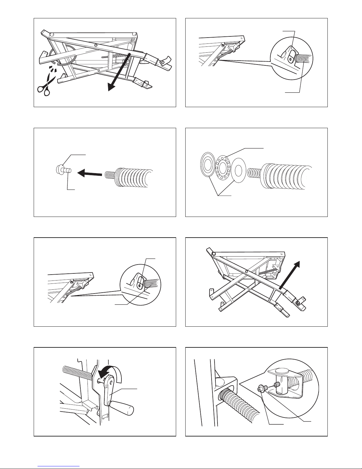
1. Take out the stand from the carton box and place it on its side. Then cut the band. (Fig. 1)
2. Move the leg in the direction of arrow and then remove the table-raising/lowering bolt with a spring from the nut holder.
(Fig. 1, 2)
3. Remove a bolt and a washer from the top of the table-raising/lowering bolt with the hex wrench.
Note: At this time, beware that a bearing unit will not come off from the bolt top. If it comes off by mistake and comes
apart, reassemble it with each groove in two plates of the bearing unit facing the bearing balls and return it to the
original position on the bolt. (Fig. 3, 4)
4. Align the table-raising/lowering bolt with the nut by adjusting the position of the table-raising/lowering bolt so that it can
be screwed in the preinstalled nut on the stand. (Fig. 5)
5. Push the leg in the direction of arrow and screw in the table-raising/lowering bolt by turning the table-raising/lowering
wheel-handle counterclockwise while pushing it in that way. (Fig. 6, 7)
6. When the table-raising/lowering bolt top comes out of the surface of the nut, screw in the bolt that was removed in
No.3 above using the hex wrench. (Fig. 8)
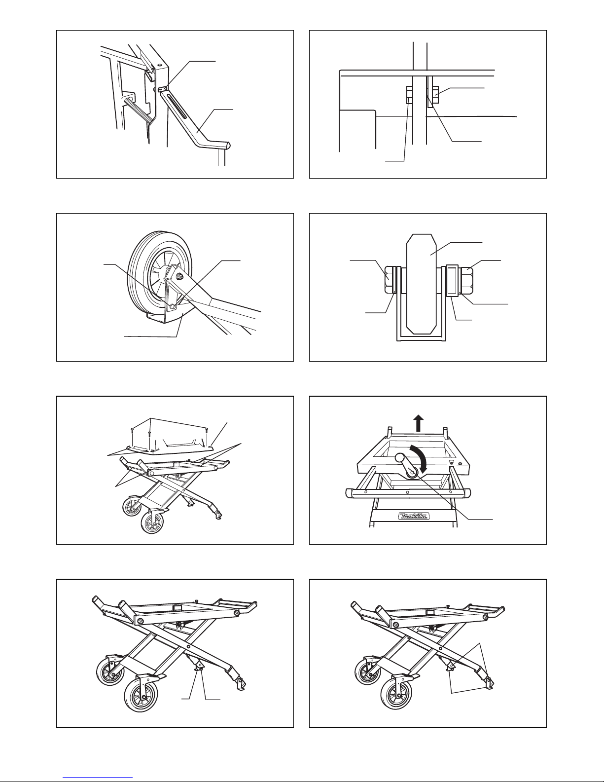
7. Insert two ends of the carrying handle with its gripping part facing upward into the holes of the stand. (Fig. 9)
8. Insert the bolt through the hole in the table and the groove in the carrying-handle and then tighten the nut and bolt
provided with the stand using two wrenches so that the carrying-handle is movable. (Fig. 10)
9. Remove a nut and washers (bigger ones) from the tire wheel using two wrenches.
Also, remove a bolt and washers (smaller ones) from it using the hex wrench.
Take the same procedure as the above for another tire wheel.
Overturn the stand and place the tire wheels on the outside surface of legs so that the locking pedal faces the inside of
the stand. (Fig. 11, 12)
Secure them to fix the axis with the bolts, washers and nuts that have been just removed by tightening firmly with two
wrenches.
Also, secure them to lock the tire wheel plate with the just removed bolt and washers.
How to use
10. When securing table saw on the table saw stand, holes on your tool base match holes in the stand. Then tighten hex
bolts (4 positions) securely. (Fig. 13)
11. Place the table saw stand on a level location. When setting up the table saw stand in the upright position, turn the
handle clockwise. (Fig. 14)
12. Adjust the levelness of the table saw stand by rotating the foot, and then secure the table saw stand by turning the nut.
(Fig. 15)
13. Secure the foot of stand to the stable and level surface using holes in the fix plates with two hex bolts. (Fig. 16)
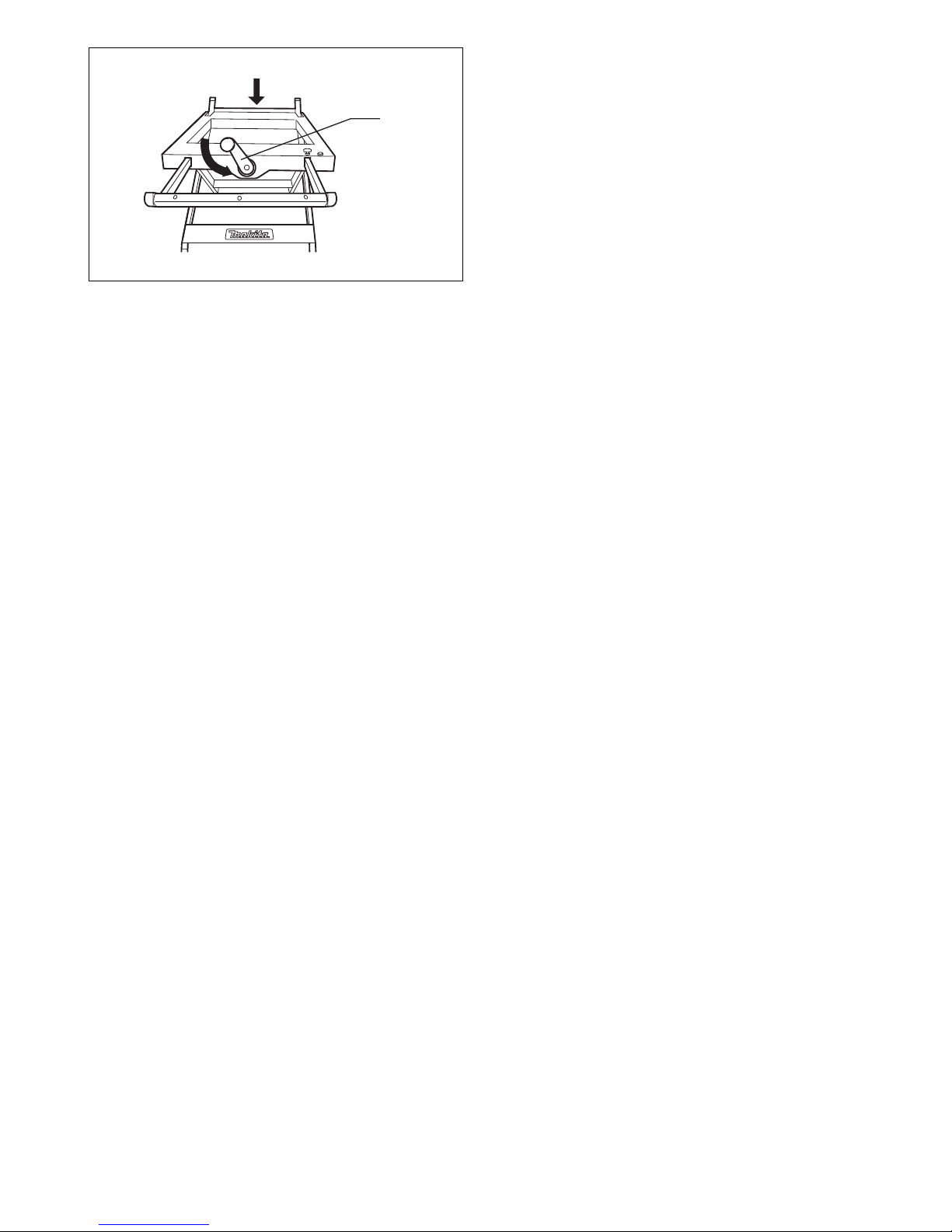
14. To fold the table saw stand, turn the handle counterclockwise. (Fig. 17)
1. Nut holder
2. Table-raising/lowering bolt
3. Washer
4. Bolt
5. Bearing
6. Plate
7. Preinstalled nut on the stand
8. Hole of the stand
9. Carrying handle
10. Nut
11. Bo lt
12. Groove in the carrying handle
13. Locking pedal
14. Bolt
15. Washer
16. Leg
17. Nut
18. Tire wheel
19. Bolt
20. Holes in your tool base
21. Holes in the stand
22. Table-raising/lowering wheel
handle
23. Foot
24. Nut
25. Hex bolts
26. Fix plate
27. Bolt
28. Washer

6
FRANÇAIS
Descriptif
ATTENTION
• Avant de poursuivre, veuillez d’abord lire et bien comprendre ce manuel et le mode d’emploi de l’outil que vous
utiliserez.
• Avant d’installer l’outil sur ce support, vous devez couper le contact et débrancher l’outil.
• Le support doit être boulonné sur une surface stable et plane, à laide des boulons prévus sur deux des quatre pieds.
• Utilisez uniquement le modèle Makita indiqué dans le mode demploi.
• Utilisez uniquement la poignée pour éviter de vous pincer les doigts en déployant le support ou en le repliant.
• Avant d’utiliser l’outil, fixez-le au support à l’aide des boulons.
• Ne pas utiliser le support sur une surface inégale ou instable.
• Ne pas monter sur le support, ni s’asseoir ou s’appuyer dessus.
• Ne jamais placer le support de scie circulaire contre un mur ou une surface similaire pour le ranger, que ce soit debout
ou sur le côté.
Montage
1. Sortez le support de sa boîte en carton et placez-le sur son côté. Ensuite, découpez la bande. (Fig. 1)
2. Déplacez le pied dans le sens de la flèche et ensuite enlevez le boulon de soulèvement/abaissement de table avec un
ressort à partir du porte-écrou. (Fig. 1, 2)
3. Retirez un boulon et une rondelle du dessus du boulon de soulèvement/abaissement de table avec la clé hexagonale.
Remarque : A cet instant, faites attention que l’unité de support ne se détache pas du haut du boulon. Si elle se
détache par erreur et se défait, remontez-la avec chaque rainure dans les deux plaques de l’unité de support faisant
face aux billes de roulement et remettez-la vers sa position d’origine sur le boulon. (Fig. 3, 4)
4. Alignez le boulon de soulèvement/abaissement de table avec l’écrou en réglant la position du boulon de soulèvement/
abaissement de table de sorte qu’il puisse être vissé dans l’écrou préinstallé sur le support. (Fig. 5)
5. Poussez le pied dans le sens de la flèche et vissez dans le boulon de soulèvement/abaissement de table en tournant
la poignée à volant de soulèvement/abaissement de table dans le sens contraire des aiguilles d’une montre tout en le
poussant de cette façon. (Fig. 6, 7)
6. Quand le haut du boulon de soulèvement/abaissement de table sort de la surface de l’écrou, vissez dans le boulon qui
avait été retiré à l’étape No.3 ci-dessus en utlisant la clé hexagonale. (Fig. 8)
7. Insérez deux extrémités de la poignée de transport avec sa pièce de fixation faisant face aux orifices du support.
(Fig. 9)
8. Insérez le boulon à travers l’orifice de la table et la rainure dans la poignée de transport et ensuite serrez le boulon et
l’écrou fourni avec le support à l’aide de deux clés de sorte que la poignée de transport soit déplaçable. (Fig. 10)
9. Retirez un écrou et les rondelles (les plus grandes) de la roue pneumatique à l’aide de deux clés.
Retirez aussi un écrou et les rondelles (les plus petites) du volant à l’aide de la clé hexagonale.
Procédez de même que ci-dessus pour une autre roue pneumatique.
Retournez le support et placez les roues pneumatiques sur la surface extérieure des pieds de sorte que la pédale de
blocage fasse face à l’intérieur du support. (Fig. 11, 12)
Sécurisez-les pour fixer l’axe avec les boulons, rondelles et écrous qui viennent d’être enlevés en serrant fortement
avec deux clés.
Aussi, sécurisez-les pour bloquer la plaque des roues pneumatiques avec les boulons et rondelles qui viennent d’être
enlevés.
Utilisation
10. Quand vous installez la scie circulaire sur le support de scie, les orifices dans la base de l’outil correspondent à ceux
du support. Serrez ensuite fermement les boulons hexagonaux (aux 4 emplacements). (Fig. 13)
11. Placez le support de table circulaire sur une surface plane. Quand vous installez le support de scie circulaire dans la
position verticale tournez la poignée dans le sens des aiguilles d’une montre. (Fig. 14)
12. Tournez les 2 pieds du support de scie circulaire pour le mettre de niveau, puis l’immobilisez en tournant l’écrou.
(Fig. 15)
13. Fixez les pieds du support sur une surface stable et plane par les orifices prévus dans les plaques de fixation, à l’aide
de 2 boulons hexagonaux. (Fig. 16)
14. Pour plier le support de scie circulaire , tournez la poignée dans le sens contraire des aiguilles d’une montre. (Fig. 17)
1. Porte-écrou
2. Table-boulon de soulèvement/
abaissement
3. Rondelle
4. Boulon
5. Roulement
6. Plaque
7. Ecrou préinstallé sur le support
8. Orifices dans le support
9. Poignée de transport
10. Écrou
11. Boulon
12. Rainure dans la poignée de
transport
13. Pédale de blocage
14. Boulon
15. Rondelle
16. Pied
17. Écrou
18. Volant pneu
19. Boulon
20. Orifices dans la base de l’outil
21. Orifices dans le support
22. Table-poignée de la roue de
soulèvement/abaissement
23. Pied
24. Écrou
25. Boulons hexagonaux
26. Plaques de fixation
27. Boulon
28. Rondelle

7
DEUTSCH
Erklärung der Gesamtdarstellung
ACHTUNG
• Lesen Sie die vorliegende Anleitung und die Betriebsanleitung des verwendeten Werkzeugs sorgfältig durch, bevor Sie
die folgenden Schritte ausführen.
• Bevor Sie ein Werkzeug auf diesem Gestell befestigen, schalten Sie stets das Gerät aus und ziehen Sie den Stecker.
• Das Gestell muss auf einer stabilen und ebenen Oberfläche mithilfe der mitgelieferten Bolzen auf zwei der vier Füße
angeschraubt werden.
• Verwenden Sie das Gestell ausschließlich mit dem in der Betriebsanleitung angegebenen Makita-Modell.
• Verwenden Sie ausschließlich den Griff, um beim Aus- und Einklappen des Gestells ein Einklemmen der Finger zu
vermeiden.
• Befestigen Sie vor der Inbetriebnahme das Werkzeug mit Hilfe der Bolzen am Gestell.
• Verwenden Sie das Gestell nicht auf einer unebenen oder instabilen Oberfläche.
• Steigen, setzen oder stellen Sie sich nicht auf das Gestell.
• Lehnen Sie zur Aufbewahrung das Gestell niemals längs oder seitwärts gegen eine Wand oder Ähnliches.
Zusammenbau
1. Nehmen Sie das Gestell aus der Verpackung und legen Sie es auf die Seite. Zerschneiden Sie dann das Band.
(Abb. 1)
2. Bewegen Sie das Bein in Pfeilrichtung und entfernen Sie dann den Bolzen zum Anheben/Absenken des Tisches mit
einer Feder aus der Mutternhalterung. (Abb. 1 und 2)
3. Entfernen Sie mit einem Inbusschlüssel einen Bolzen und eine Unterlegscheibe von der Oberseite des Bolzens zum
Anheben/Absenken des Tisches.
Hinweis: Achten Sie darauf, dass sich zu diesem Zeitpunkt die Lagereinheit nicht vom Oberbolzen löst. Wenn sie sich
aus Versehen löst und auseinander geht, setzen Sie sie mit jeder Kerbe in zwei Platten der Lagereinheit in Richtung
der Lagerkugeln wieder zusammen und bringen Sie sie wieder in die ursprüngliche Position am Bolzen. (Abb. 3
und 4)
4. Richten Sie den Bolzen zum Anheben/Absenken des Tisches mit der Mutter aus, indem Sie die Position des Bolzens
zum Anheben/Absenken des Tisches anpassen, sodass er in die vorinstallierte Mutter am Gestell eingeschraubt
werden kann. (Abb. 5)
5. Schieben Sie das Bein in Pfeilrichtung und schrauben Sie den Bolzen zum Anheben/Absenken des Tisches ein,
indem Sie den Kurbelgriff zum Anheben/Absenken des Tisches gegen den Uhrzeigersinn drehen, während Sie in
diese Richtung drücken. (Abb. 6 und 7)
6. Wenn sich die Spitze des Bolzens zum Anheben/Absenken des Tisches aus der Oberseite der Mutter löst, schrauben
Sie den Bolzen ein, der in Schritt 3 oben mit einem Inbusschlüssel entfernt wurde. (Abb. 8)
7. Fügen Sie die beiden Enden des Tragegriffs in die Löcher am Gestell ein, sodass der Griffabschnitt nach oben zeigt.
(Abb. 9)
8. Schieben Sie den Bolzen durch das Loch im Gestell und die Kerbe im Tragegriff und ziehen Sie dann die mitgelieferte
Mutter und den Bolzen mit zwei Schraubschlüsseln am Gestellt fest, sodass sich der Tragegriff bewegen lässt.
(Abb. 10)
9. Entfernen Sie eine Mutter und die Unterlegscheiben (die größeren Scheiben) mit zwei Schraubschlüsseln vom
Radreifen.
Entfernen Sie auch einen Bolzen und die Unterlegscheiben (die kleineren Scheiben) mit einem Inbusschlüssel.
Führen Sie die gleichen Schritte für mögliche weitere Radreifen durch.
Drehen Sie das Gestell um und platzieren Sie die Radreifen so an der äußeren Oberfläche der Beine, dass das
Sperrpedal zur Innenseite des Gestells zeigt. (Abb. 11 und 12)
Sichern Sie sie mit den Bolzen, Unterlegscheiben und Muttern, die zuvor entfernt wurden, an der Achse, indem Sie sie
mit zwei Schraubschlüsseln sicher festziehen.
1. Mutternhalterung
2. Bolzen zum Anheben/Absenken
des Tisches
3. Unterlegscheibe
4. Bolzen
5. Lager
6. Tiefeneinstellskala
7. Vorinstallierte Mutter am Gestell
8. Loch am Gestell
9. Tragegriff
10. Mutter
11. Bolzen
12. Kerbe im Tragegriff
13. Sperrpedal
14. Bolzen
15. Unterlegscheibe
16. Bein
17. Mutter
18. Radreifen
19. Bolzen
20. Bohrungen im Gleitschuh Ihres
Werkzeugs
21. Bohrungen im Gestell
22. Kurbelgriff zum Anheben/
Absenken des Tisches
23. Fuß
24. Mutter
25. Sechskantschrauben
26. Befestigungsplatte
27. Bolzen
28. Unterlegscheibe

8
Sichern Sie sie außerdem mit den zuvor entfernten Bolzen und Unterlegscheiben so, dass die Radreifenplatte
gesperrt wird.
Verwendung
10. Wenn Sie die Tischsäge auf dem Gestell sichern, entsprechen die Bohrungen im Gleitschuh Ihres Werkzeugs den
Bohrungen im Gestell. Ziehen Sie dann die Sechskantschrauben (4 Positionen) fest an. (Abb. 13)
11. Stellen Sie das Gestell auf einer ebenen Fläche auf. Stellen Sie das Gestell aufrecht auf und drehen Sie den Griff im
Uhrzeigersinn. (Abb. 14)
12. Stellen Sie das Gestell eben ein, indem Sie den Fuß drehen, und sichern Sie dann das Gestell durch Drehen der
Mutter. (Abb. 15)
13. Sichern Sie mithilfe der Bohrungen in den Befestigungsplatten und mit zwei Sechskantschrauben den Gestellfuß an
der stabilen und ebenen Oberfläche. (Abb. 16)
14. Um das Gestell zusammenzuklappen, drehen Sie den Griff gegen den Uhrzeigersinn. (Abb. 17)
 Loading...