

Makita Maktec MT961, Maktec MT962, Maktec MT963 Technical Information
T
ECHNICAL INFORMATION
PRODUCT
P 1/ 10
Model No.
Description
MT961, MT962, MT963
Angle Grinders 100mm (4"), 115mm (4-1/2"), 125mm (5")
CONCEPT AND MAIN APPLICATIONS
These new angle grinders have been developed as the aesthetic
change models of the predecessors MT951/ MT952/ MT953.
Their main features are:
New slide switch (two action safety switch) and wheel cover
in compliance with the requirements of the new regulations
Industrial performance and durability at less expense
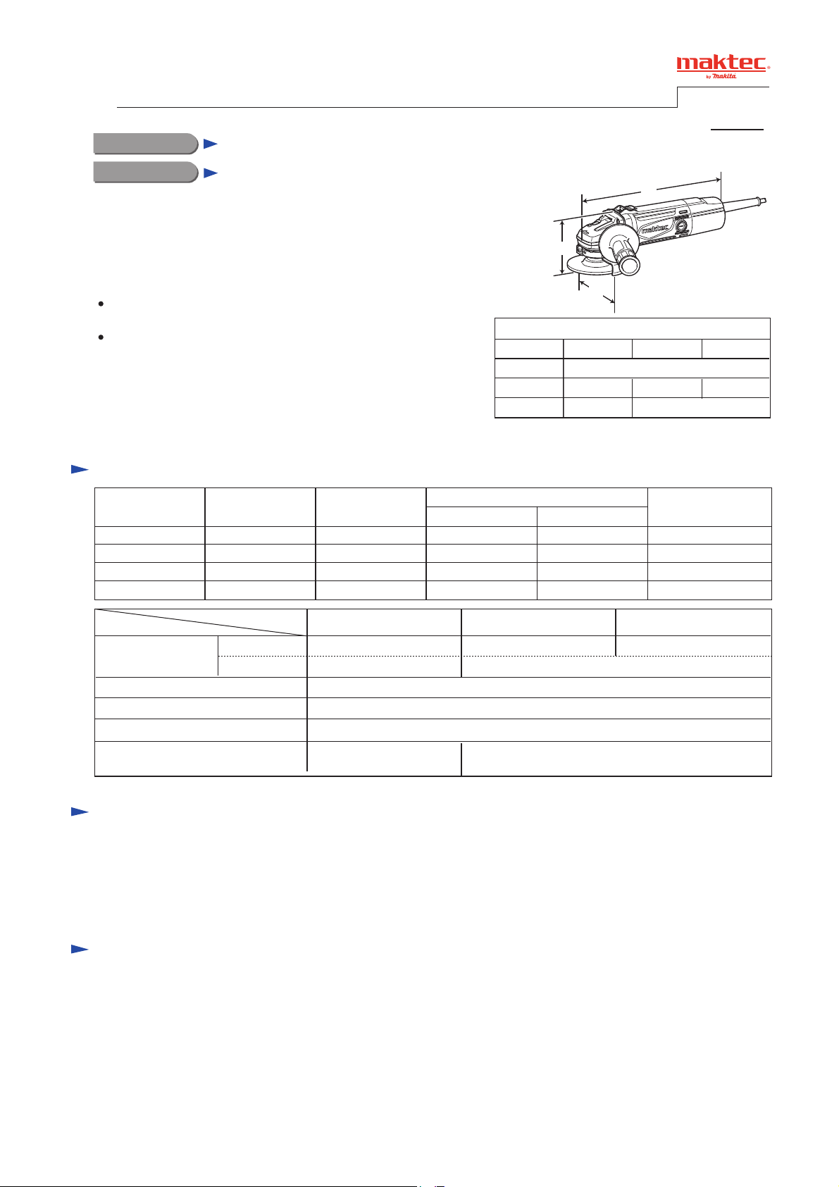
Specification
Voltage (V) Cycle (Hz)
110
120
220
230-240
Current (A)
5.5
5.0
2.7
2.5
50/60
50/60
50/60
50/60
H
W
Dimensions: mm (")
Model No.
Length (L)
Width (W)
Height (H)
Continuous Rating (W)
Input Output
570
---
570
570
MT961
118 (4-5/8)
96 (3-3/4)
320
320
350
350
L
MT962 MT963
270 (10-5/8)
129 (5-1/8)
Max. Output (W)
139 (5-1/2)
105 (4-1/8)
550
550
650
650
Specification
Wheel size: mm (")
No load speed: min.
Protection against electric shock
Power supply cord: m (ft)
Weight according to
EPTA-Procedure 01/2003*: kg (lbs)
* With Side grip, Wheel cover, Inner flange, Lock nut
Model No.
Diameter
Hole diameter
-1 = rpm
MT961
100 (4)
16 (5/8)
1.9 (4.1) 2.0 (4.4)
MT962
115 (4-1/2)
11,000
Double insulation
2.0 (6.6)
Standard equipment
Lock nut wrench 20 ...................... 1 (for MT961)
Lock nut wrench 35 ...................... 1 (for MT962/ MT963)
Side grip ....................................... 1
Note: The standard equipment for the tool shown above may vary by country.
Optional accessories
Wheel cover for Cut-off wheel
MT963
125 (5)
22.23 (7/8)
P 2/ 10
Repair
CAUTION: Repair the machine in accordance with “Instruction manual” or “Safety instructions”.
[1] NECESSARY REPAIRING TOOLS
Code No. Description Use for
1R004 Retaining ring S pliers ST-2N removing Ring spring 11 from Spindle
1R005 Retaining ring R pliers RT-2N removing Retaining ring R-32 from Bearing box
1R026 Bearing setting pipe 16-8.2 removing Spindle from Spiral bevel gear 36
1R232 Pipe 30 supporting Bearing box when removing Spindle
1R268 Spring pin extractor 3 disassembling Shaft lock mechanism
1R269 Bearing extractor removing Ball bearing
1R281 Round bar for arbor 7-50 locking Switch knob when separating Switch lever from Switch knob
1R282 Round bar for arbor 8-50 removing Spindle
1R291 Retaining ring S and R pliers removing / assembling Retaining ring S-6 from / to Armature shaft
[2] LUBRICATIONS
Apply the following lubricant to protect parts and product from unusual abrasion.
Item No.
17
Description
Gear housing complete
Gear room
Lubricant
Makita grease N No.1
AmountPortion to lubricate
10g
Fig. 1
17
[3] DISASSEMBLY/ASSEMBLY
[3]-1. Armature, Spiral bevel gear 11, Ball bearings 6000ZZ and 607ZZ
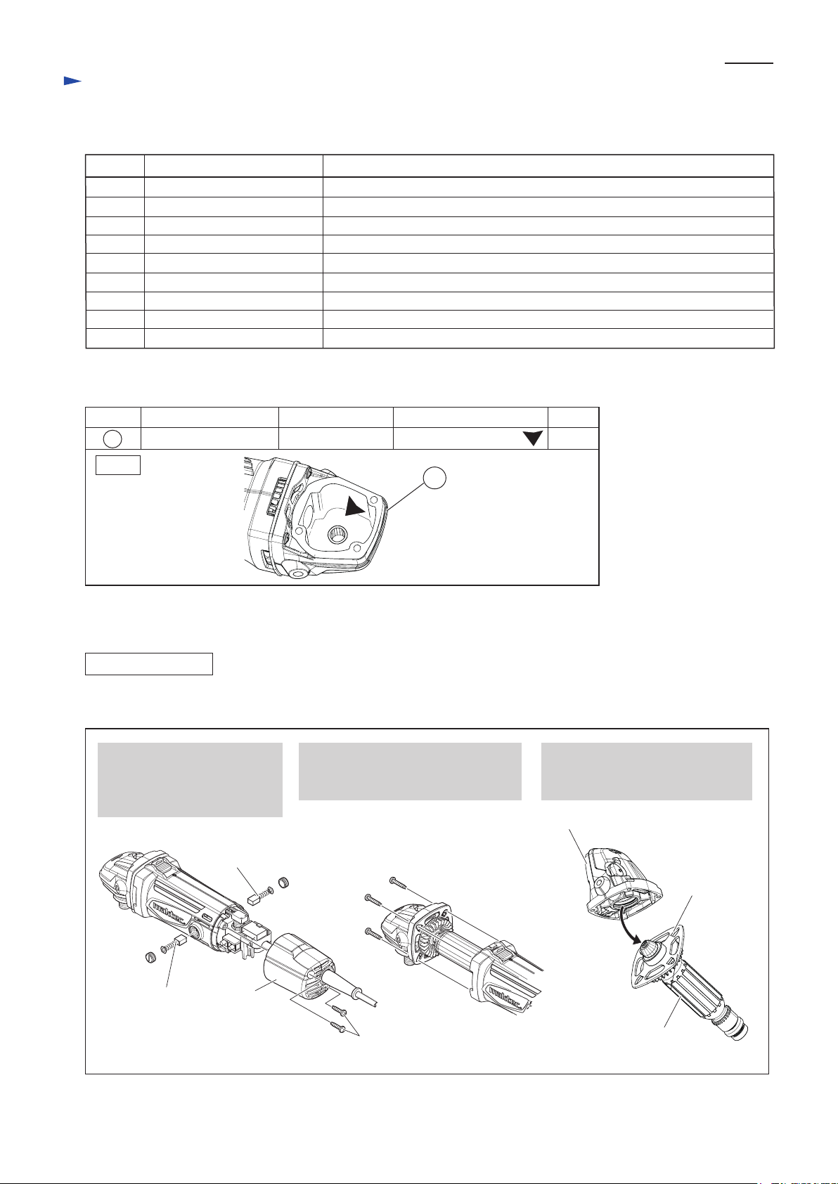
DISASSEMBLING
(1) Remove Armature. (Fig. 2)
Fig. 2
1. Remove Carbon brushes and
two 4x18 Tapping screws,
and then remove Rear cover
from Motor housing.
Carbon brush
2. Remove four 4x22 Tapping screws
and Gear housing section from
Motor housing.
4x22 Tapping screw (4pcs.)
3. Remove Armature together with
Bearing box from Gear housing
complete.
Gear housing complete
Carbon brush
Rear cover
4 x 18 Tapping screw
(2pcs.)
Bearing box
Armature
epair
R
[3] DISASSEMBLY/ASSEMBLY
[3]-1. Armature, Spiral bevel gear 11, Ball bearings 6000ZZ and 607ZZ (cont.)
DISASSEMBLING
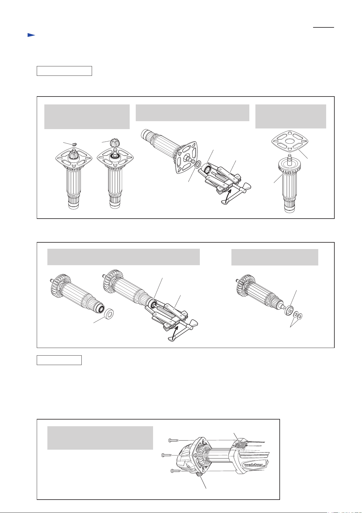
(2) Remove Helical gear 11, Ball bearing 6000ZZ and Bearing retainer 69 from Armature. (Fig. 3)
Fig. 3
P 3/ 10
4. Remove Retaining ring S-6
with 1R291. Helical gear 11
can now be removed by hand.
Retaining
ring S-6
(3) Remove Ball bearing 607ZZ from the commutator end of Armature. (Fig. 4)
Fig. 4
After removing Rubber ring 19, remove Ball bearing 607ZZ
with 1R269.
Helical
gear 11
5. Remove Ball bearing 6000ZZ with 1R269,
and then remove Flat washer 10.
Ball bearing
6000ZZ
Flat washer 10
Ball bearing 607ZZ
1R269
6. Armature can be now
removed from Bearing
retainer 69.
1R269
Armature
Remove two Flat washers 7 and
Insulation washer.
Insulation
washer
Bearing
retainer 69
Rubber ring 19
Flat washer 7 (2pcs.)
ASSEMBLING
(1) Do the reverse of the disassembling steps. (Figs. 4, 3, 2)
Note:
a. Do not forget to put two Flat washer 7 before assembling Ball bearing 607ZZ. (right in Fig. 4)
b. Put Flat washer 10, before assembling Ball bearing 6000ZZ. (center of Fig. 3)
c. Be sure to use new Retaining ring S-6 because removed one was damaged in the removal process. (left in Fig. 3)
d. Assemble Gear housing section to Motor housing by screwing four 4 x 22 Tapping screws. (Fig. 5)
Fig. 5
Spindle face from Gear housing section
to the opposite side of Switch knob of
Motor housing.
Spindle
Switch knob
 Loading...