

Makita Maktec MT925, Maktec MT925G Technical Information
T
ECHNICAL INFORMATION
PRODUCT
P 1/ 7
Model No.
MT925, MT925G
Description Finishing Sander
CONCEPT AND MAIN APPLICATIONS
Model MT925 has been developed as the cosmetic change
model of maktec finishing sander MT920, featuring:
• Slim grip for easy horizontal and overhead applications
• Industrial performance and durability at less expense
Model MT925G is Green housing model exclusively developed
for Korean market.
Specification
Voltage (V)
110
220
230 0.9 50/60 180 5025
240
Current (A)
1.7
0.9
0.8
Cycle (Hz)
50/60
50/60
50/60
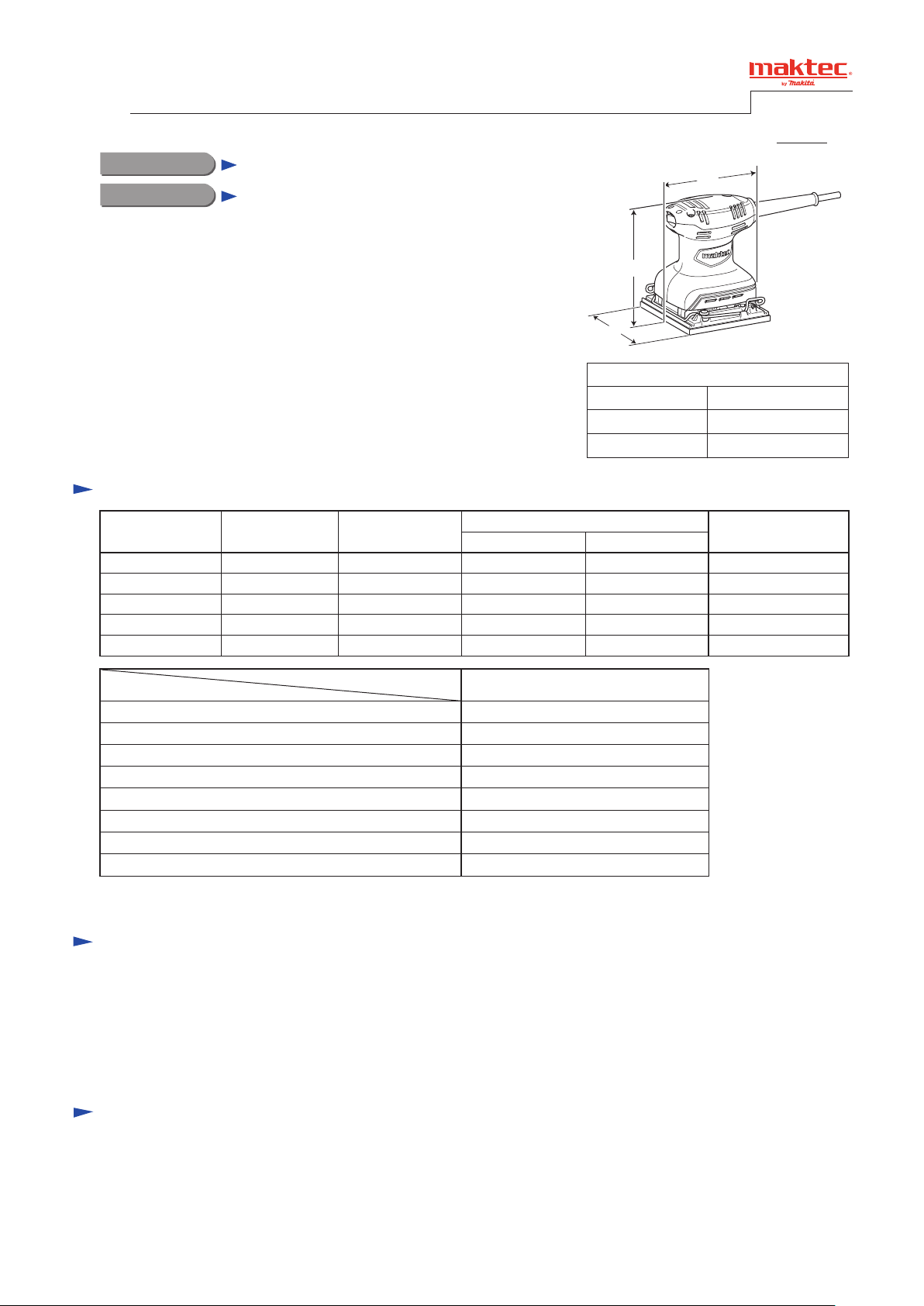
H
W
Dimensions: mm (")
Length (L)
Width (W)
Height (H)
Continuous Rating (W)
Input Output
180
180
180
25
25120 1.6 50/60 --- 50
25
25
L
110 (4-5/16)
112 (4-3/8)
133 (5-1/4)
Max. Output (W)
50
50
50
Specification
Orbits per minute: opm= min.ˉ¹
Sanding strokes: spm= min.ˉ¹
Abrasive paper size: mm (")
Pad size: mm (")
Orbit diameter: mm (")
Protection from electric shock Double insulation
Power supply cord: m (ft)
Weight according to EPTA-Procedure 01/2003: kg (lbs)
Model
MT925/ MT925G
14,000
28,000
114 x 140 (4-1/2 x 5-1/2)
112 x 102 (4-3/8 x 4)
ø1.5 (1/16)
2.0 (6.6)
0.89 (2.0)
Standard equipment
Abrasive paper 114-60 ....................... 2
Abrasive paper 114-100 ..................... 2
Abrasive paper 114-150 ..................... 2
Note: The standard equipment for the tool shown above may vary by country.
Optional accessories
TBA
P 2/ 7
Repair
CAUTION: Repair the machine in accordance with “Instruction manual” or “Safety instructions”.
[1] NECESSARY REPAIRING TOOLS
Code No. Description Use for
1R027 Bearing setting pipe 18-10.2 removing Armature
1R269 Bearing extractor removing Ball bearings 629DDW, 606ZZ
[2] LUBRICATION
Lubrication is not required for this product because no gear is used for transmission.
[3] DISASSEMBLY/ASSEMBLY
[3] -1. Armature
DISASSEMBLING
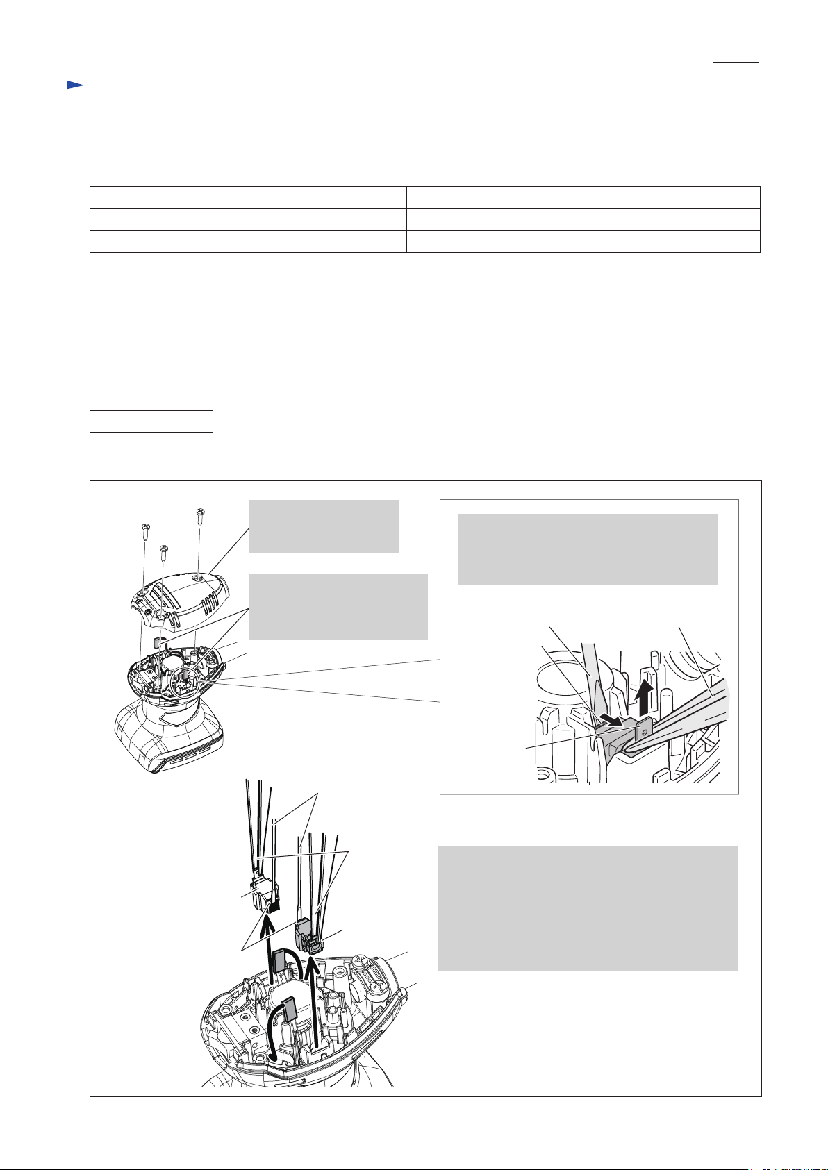
(1) Remove Carbon brushes and Brush holders from Motor housing as drawn in Fig. 1.
Fig. 1
Brush holder
Carbon brushes
1. Remove Top cover by
unscrewing three 4x18
Tapping screws.
2. Disconnect Field lead wires
by pulling off Receptacles
from the terminals of Brush
holders.
Small slotted
Screwdriver
Long nose
pliers
Brush holder
3. Insert a small slotted screwdriver between
Armature’s commutator and Carbon brush
carefully, and hold the terminal of Brush
holder with Long nose pliers.
Small slotted
Screwdriver
Carbon brush
Terminal of
Brush holder
4. Then, lift up Brush holder vertically together with
Carbon brush while pressing Carbon brush with
the screwdriver.
Remove the other Brush holder and Carbon brush
in the same manner.
Note: Do not bend terminals of Brush holders.
Do not scratch the commutator of Armature.
Long nose
pliers
Repair
[3] DISASSEMBLY/ASSEMBLY
[3] -1. Armature (cont.)
DISASSEMBLING
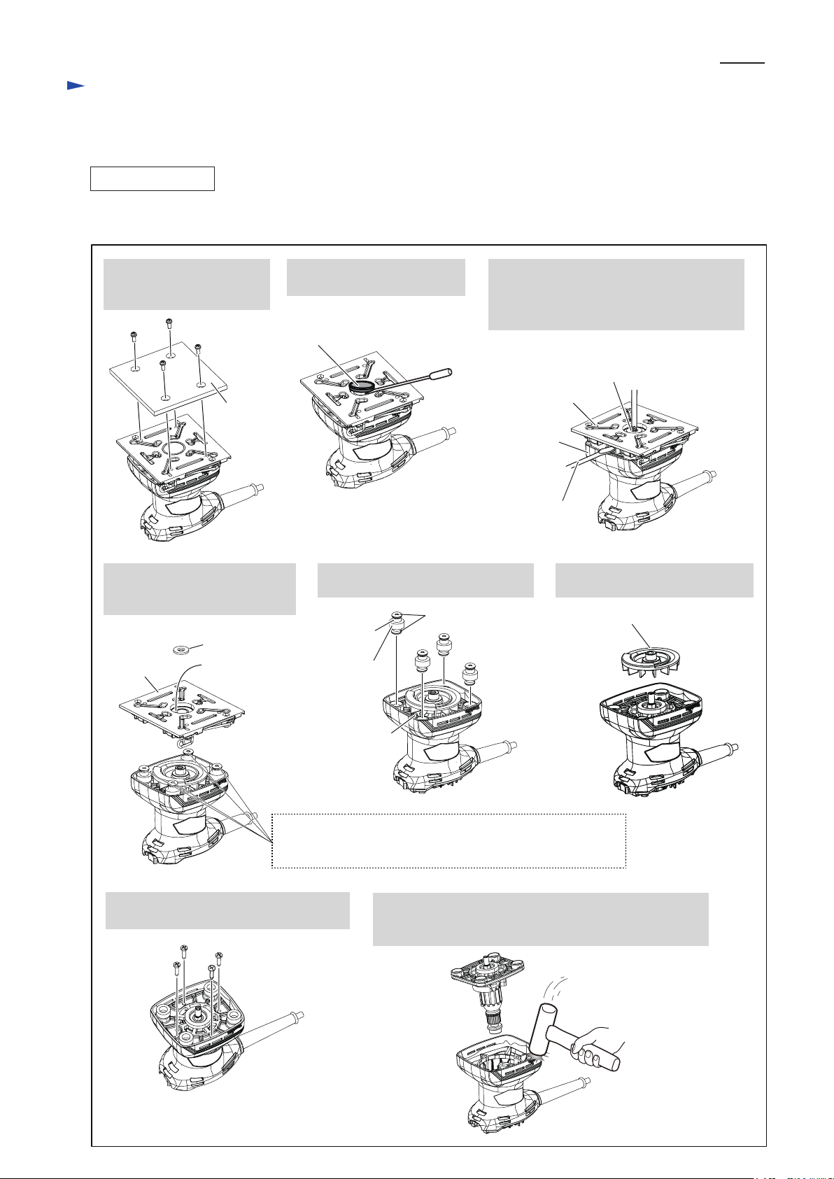
(2) Disassemble the parts in bottom section and remove Armature from Motor housing as drawn in Fig. 2.
Fig. 2
P 3/ 7
1. Remove Pad complete
by unscrewing four
M4x10 +Pan head screws.
Pad complete
4. After removing Flat washer 6,
Base is removed together with
Ball bearing 6001ZZ.
Flat washer 6
Base
Ball bearing
6001ZZ
2. Remove Cap 28 by levering
up with slotted screwdriver.
Cap 28
5. Remove Sponge sleeves and Foots
with O rings 4 from Bearing box.
Foot
(4 pcs.)
Sponge
sleeve
(4 pcs.)
O ring 4 (8 pcs.)
3. While holding Fan 65 by inserting slotted
screwdriver from the gap between Motor
housing and Base, remove M4x10
+Countersunk head screw.
M4x10 +Countersunk
head screw
Base
Motor
housing
Slotted
screwdriver
6. Remove Fan 65 from Armature
shaft.
Fan 65
Bearing box
Caution:
Sponge sleeves, Foots and O rings may be left to Base.
Be careful not to lose them when Base is turned upside down.
7. Remove four 4x18 Tapping screws that
fasten Bearing box to Motor housing.
4x18 Tapping
screws
8. Disassemble Armature assembly and Bearing box from
Motor housing by tapping the skirt portion of Motor
housing with plastic hammer.
 Loading...