

Makita Maktec MT241 Technical Information
T
Models No.
ECHNICAL INFORMATION
MT241
PRODUCT
P 1/ 9
Description
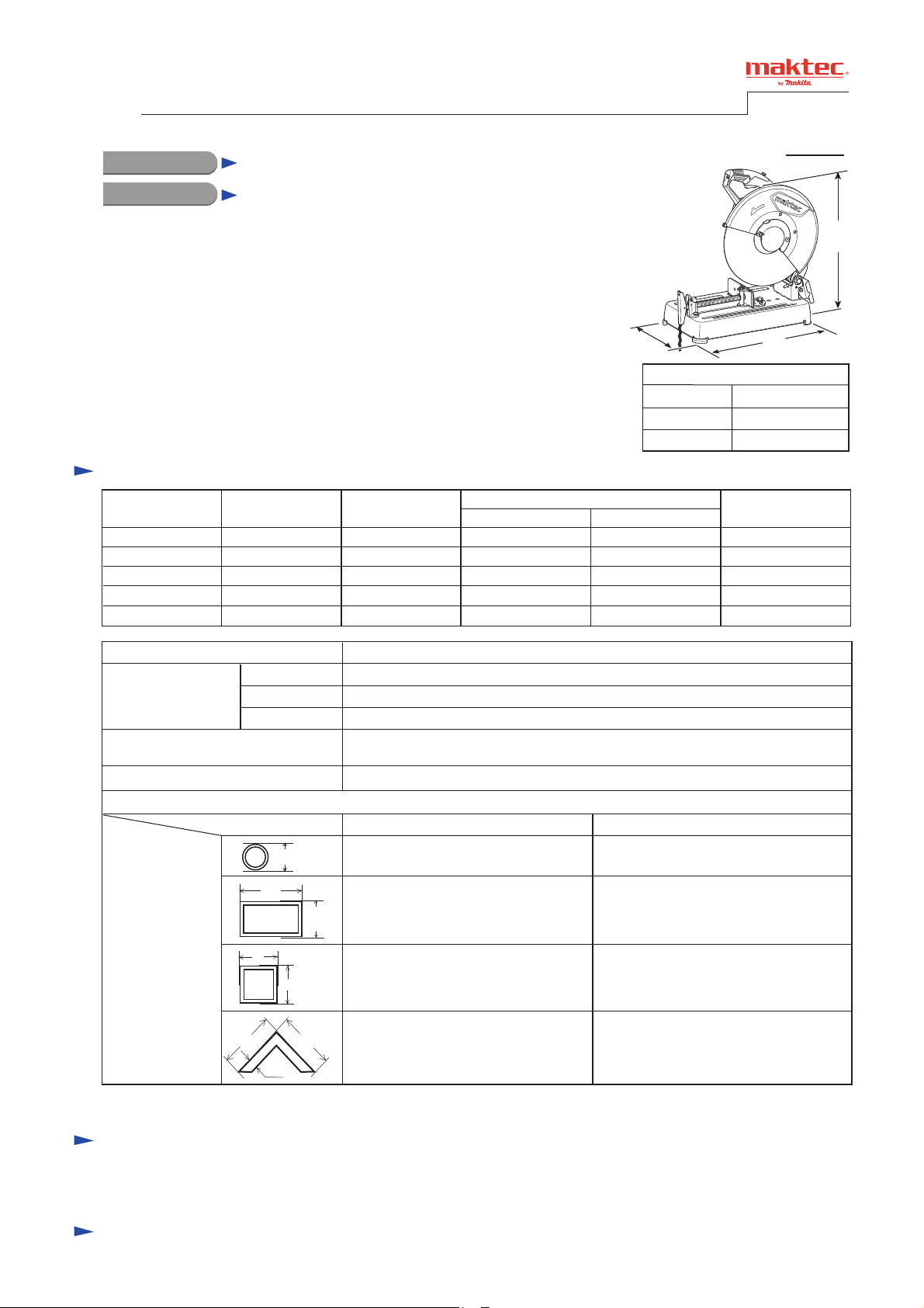
355mm (14") Portable Cut-Off
CONCEPT AND MAIN APPLICATIONS
Model MT241 has been developed as the aesthetic change model
of maktec MT240, featuring industrial performance and durability
at less expense.
Specification
Voltage (V) Cycle (Hz)
110
120 15.0
220
230
240
Current (A)
15.0
9.6
9.2
8.8
50/60
50/60
50/60
50/60
50/60
W
Dimensions: mm (")
Length (L)
Width (W)
Height (H)
Continuous Rating (W)
Input Output
1,650
--2,000 1,400 3,000
2,000 1,400 3,000
2,000 1,400 3,000
L
500 (19-3/4)
280 (11)
620 (24-3/8)
Max. Output(W)
2,500900
2,500900
H
No load speed: min-1= rpm.
Diameter
Wheel size: mm (")
Weight according to
EPTA-Procedure 01/2003*
Cord length: m (ft)
Capacity: mm (")
Form of materials
D: Diameter
W: Width
H: Height
S: Side
T: Thickness
*1 with Abrasive cut-off wheel 355
*2 Weight shown above is the model with Center cap.
Arbor
Thickness
1: kg (lbs)
Miter angle
D
W
W
H
S S
T
2.0 (6.6) for Brazil, 2.5 (8.2) for Oceania, 3.0 (9.8) for other countries
H x W: 102 (4) x 194 (7-5/8)
H
H x W: 70 (2-3/4) x 233 (9-1/8)
H x W: 119 (4-11/16) x 119 (4-11/16) H x W: 106 (4-3/16) x 106 (4-3/16)
S x S: 137 (5-3/8) x 137 (5-3/8),
3,800
355 (14)
25.4 (1)
3 (1/8)
15.7 (34.6)*
0°
ø115 (4-1/2) ø115 (4-1/2)
T: 10 (3/8)
2
45°
H x W: 115 (4-1/2) x 103 (4-1/16)
S x S: 100 (4) x 100 (4),
T: 10 (3/8)
Standard equipment
Socket wrench 17 ................................ 1
Abrasive cut-off wheel 355 ............................... 1
Note: The standard equipment for the tool shown may vary by country.
Optional accessories
No
P 2/ 9
Repair
CAUTION: Repair the machine in accordance with “Instruction manual” or “Safety instructions”.
[1] NECESSARY REPAIRING TOOLS
Code No. Description Use for
1R003 Retaining Ring S Pliers ST-2N Removing Pipe 20-128
1R269 Bearing extractor Removing Ball bearing 6000ZZ from spindle
[2] LUBRICATIONS
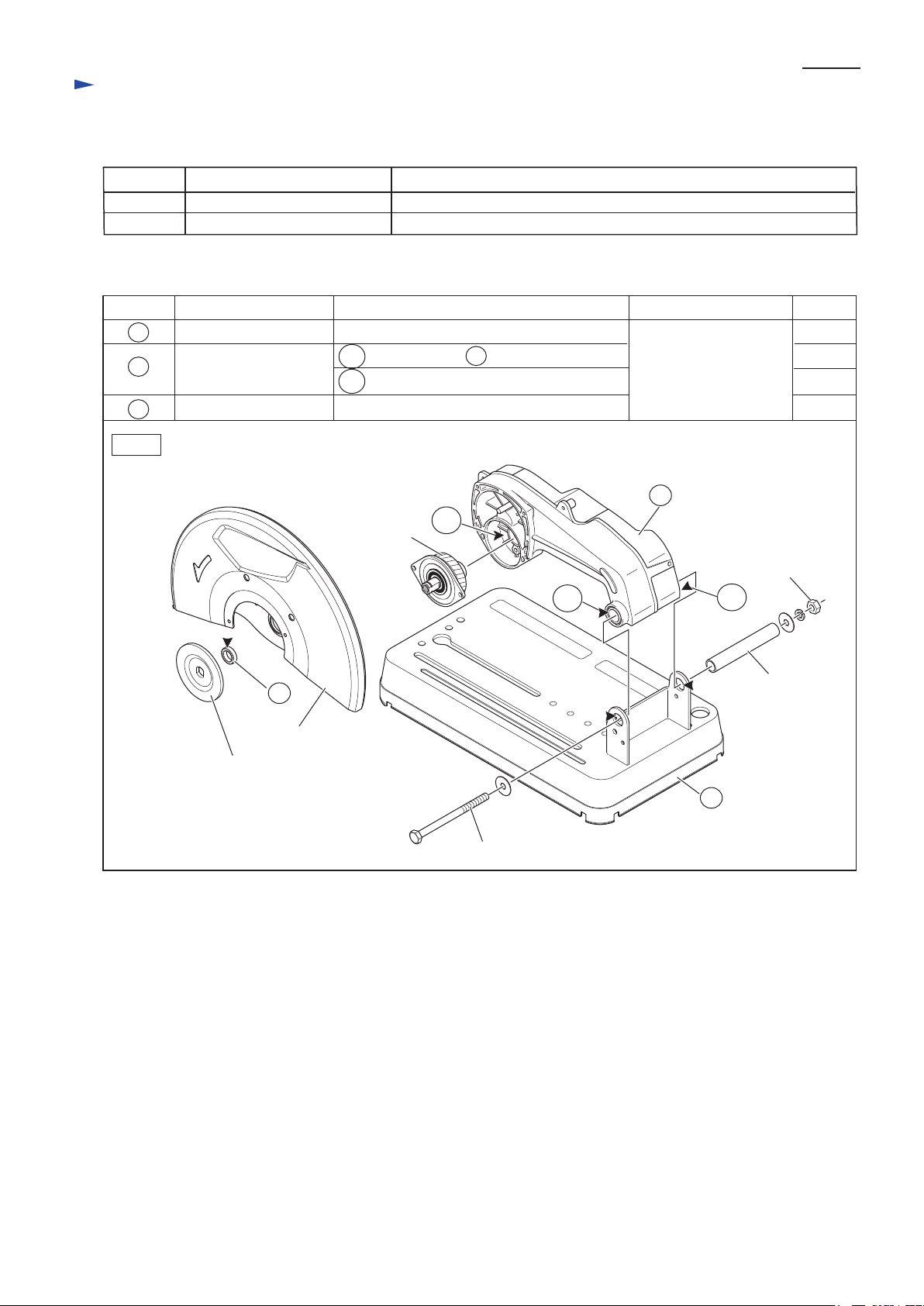
Apply the following grease to the portions pointed with triangles to protect parts and product from unusual abrasion.
Item No.
16
57
86
Fig. 1
Description
Ring 17
Gear housing complete
Base
16
Safety cover
Outside where Safety cover contacts
57a Surface where 86 Base contacts
57b Gear room where Helical gear 49 rotates
Punched hole for Pipe 20-128 passing
57b
Helical gear 49
57a
Lubricant AmountPortion to lubricate
Makita Grease N No.1
57
M10-17 Hex nut
57a
Pipe 20-128
a little
2 g
25 g
a little
Inner flange
86
M10x140 Hex bolt
Repair
[3] DISASSEMBLY/ASSEMBLY
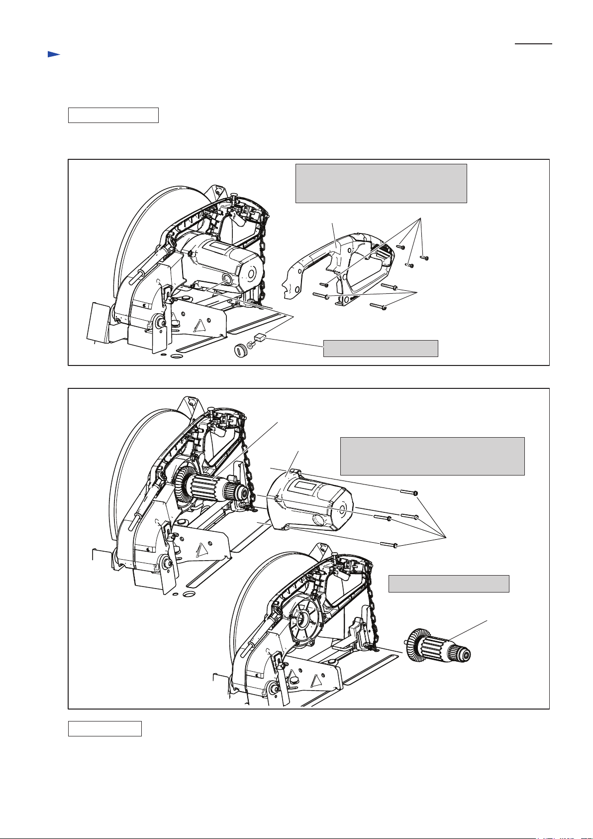
[3]-1. Armature
DISASSEMBLING
Disassemble Armature (Fig. 2, Fig. 3).
Fig. 2
P 3/ 9
1. Remove Handle (L) by unscrewing
four Tapping screws and three M5x30
Pan head screws.
4x18 Tapping screw (4 pcs.)
Handle (L)
M5x30 Pan
head screw (3pcs.)
Fig. 3
Armature
Motor housing
2. Remove carbon brushes.
3. Unscrew four M5x30 Pan head screws
and remove Motor housing.
Now, Armature comes into your sight.
M5x30 Pan
head screw (4pcs.)
4. Armature can be replaced.
Armature
ASSEMBLING
Take the reverse step of Disassembling (Fig. 3, Fig. 2).
 Loading...