

Makita Makstar DC18SD Technical Information
T
ECHNICAL INFORMATION
Models No.
DC18SD
PRODUCT
P 1 / 3
Description
Charger
CONCEPT AND MAIN APPLICATIONS
Cost-effective charger DC18SD has been launched for worldwide owners
of Makita slide-on type 7.2-18V Li-ion and Ni-MH batteries.
1.5 Ah Li-ion Battery can be charged in 30 minutes. (3.0Ah: 60 minutes)
Innovative computer controlled charging system realized most suitable
charge by making the digital communication between charger and battery.
See detailed information as follows.
This charger contains trickle charging function.
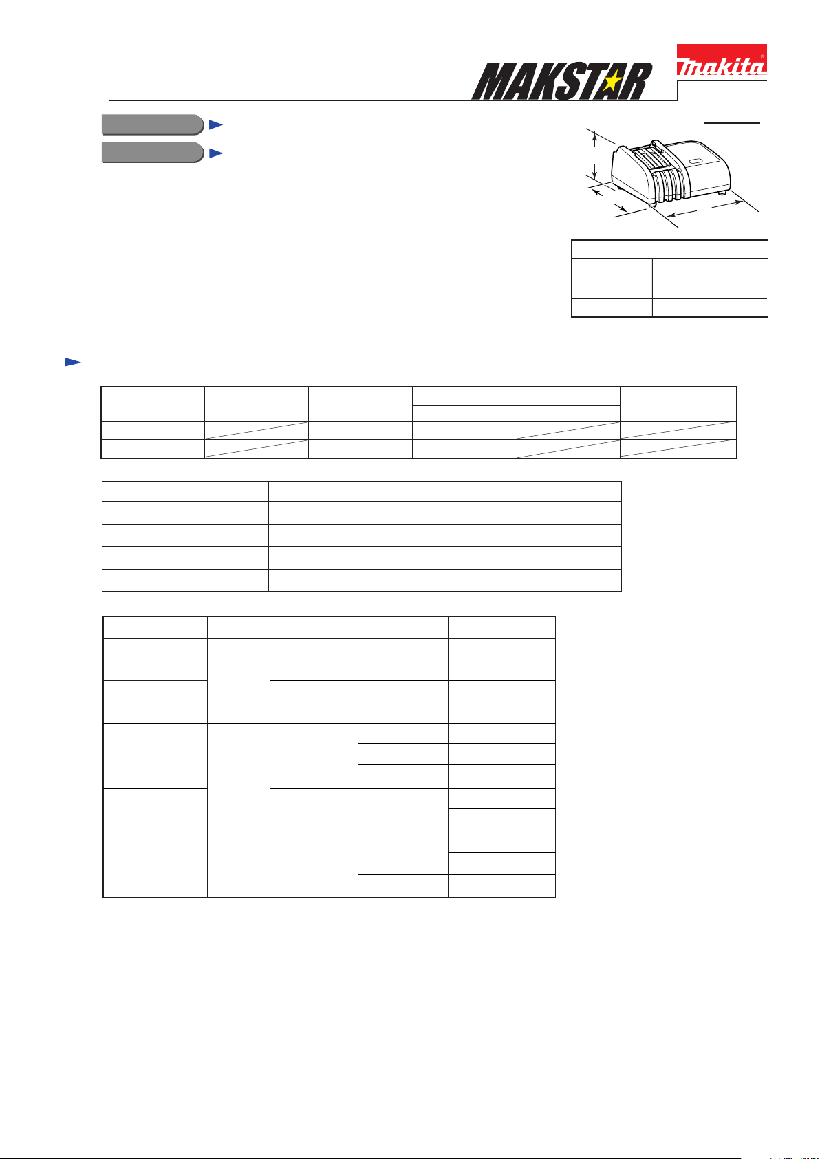
Specification
Voltage (V) Cycle (Hz)
110-120
220-240
Output voltage : V
Output current : A
Power Supply Cord: m ( ft )
Net weight: Kg (lbs)
Current (A)
50 - 60
50 - 60
DC 7.2 - 18
Continuous Rating (W)
Input Output
65
65
DC 2.6
NoDouble Insulation
2.0 (6.6)
0.7 (1.5)
H
L
Dimensions: mm (")
Length (L)
Width (W)
Height (H)
Max. Output(W)
W
151 (5-15/16)
183 (7-1/4)
88 (3-1/2)
Cell Voltage: VCapacity: AhCharging time Battery
Approx. 30 min.
Li-ion
Approx. 60 min.
Approx. 40 min.
Ni-MH
Approx. 70 min.
Note: The above figures about charging time may differ from condition to condition on batteries' temperature
or room temperature.
1.5
3.0
2.0
3.3
14.4
18
14.4
18
9.6
12
14.4
9.6
12
14.4 BH1433
BL1415
BL1815
BH1430 / A
BH1830
BH9020 / A
BH1220 / C
BH1420
BH9033
BH9033A
BH1233
BH1233C
P 2 / 3
Repair
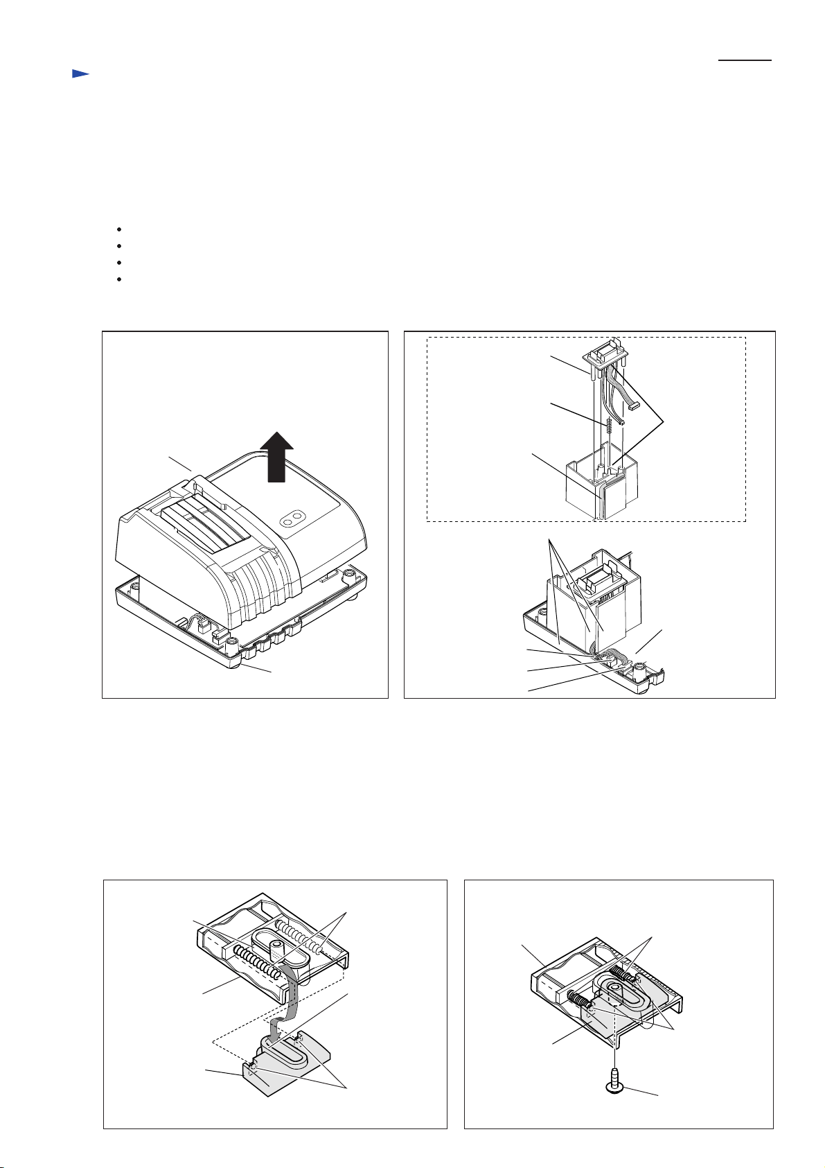
[1] Replacing Terminal unit and Terminal cover
1) Turn Charger upside down.
2) Remove four Caps 13 and BT4x20 Tapping screws.
Note: Be careful not to lose Caps 13.
3) Turn Charger over again and remove Charger case complete. (Fig. 1)
4) When replacing Terminal unit, disconnect Connector CN1 and CN2 from Charging circuit and install the new Terminal
unit carefully as follows: (Fig. 2)
Do not pinch Lead wires between the walls of Charger case cover and Charger case complete.
Route Lead wires with Lead wire holder (indicated by gray color in Fig. 2) and Clip.
Connect Connector CN1 and CN2 to Charging circuit securely.
Put the both ends of Compression spring 4 (Part No. 233194-8) to each boss of Charger case cover and Terminal unit
and insert Three pins of Terminal unit into holes of Charger case cover.
Fig. 1 Fig. 2
Pin of Terminal unit
Compression spring 4
(233194-8)
Charger case complete
Charger case cover
5) When replacing Terminal cover;
(1) Remove BT3x10 Tapping screw behind Charger case cover.
(2) Separate Terminal cover from Charger case complete carefully so as not to lose two Compression springs 4
(Part No. 231474-6) behind Terminal cover.
(3) Compressing Compression springs 4 in new Terminal cover, fit the oval wall of Charger case complete into the oval
wall of Terminal cover and secure Terminal cover to Charger case complete by tightening BT3x10 Tapping screw.
(Figs. 3 and 4)
Note: 1) The tightening torque has to be 0.5N.m.
2) Use two different Compression springs 4 (233194-8 and 231474-6) for their appropriate positions.
Fig. 3 Fig. 4
Lead wire holder
Walls of Charger case cover
Clip
Connector CN2
Connector CN1
Boss for
Compression
spring 4
Charging circuit
Oval wall of
Terminal cover
Terminal cover
Compression
spring 4
(231474-6)
Oval wall of
Charger case
complete
Boss of charger
case complete
Terminal cover
Charger case
complete
Compression
spring 4 (231474-6)
Boss of charge
case complete
BT3x10 Tapping
screw
 Loading...