

Makita MAKSTAR DC18RA Technical Information
T
ECHNICAL INFORMATION
Models No.
Description
DC18RA
Charger
CONCEPT AND MAIN APPLICATIONS
Considering the future demand for slide type 7.2V Li-ion and Ni-MH
battery, the above product has been launched with wider changeable range.
This new face contains trickle charging function.
Its brief benefits are mentioned below.
1. Only 22 minutes for full-charge of 3.0 Ah Li-ion Battery
2. Innovative computer controlled charging system realized most suitable
charge by making the digital communication between charger and battery.
3. Cooling system to keep the ideal temperature for charge.
4. Power display for battery; It displays the charging amounts of battery
in two steps. (less than 80% or more than 80% of charge)
5. The adapter ADP04 (optional accessory) enables to charge the existing
Ni-Cd and Ni-MH batteries.
6. The adapter ADP03 (optional accessory) enables to refresh inactive
batteries
7. Selectable melody sound of completed charging
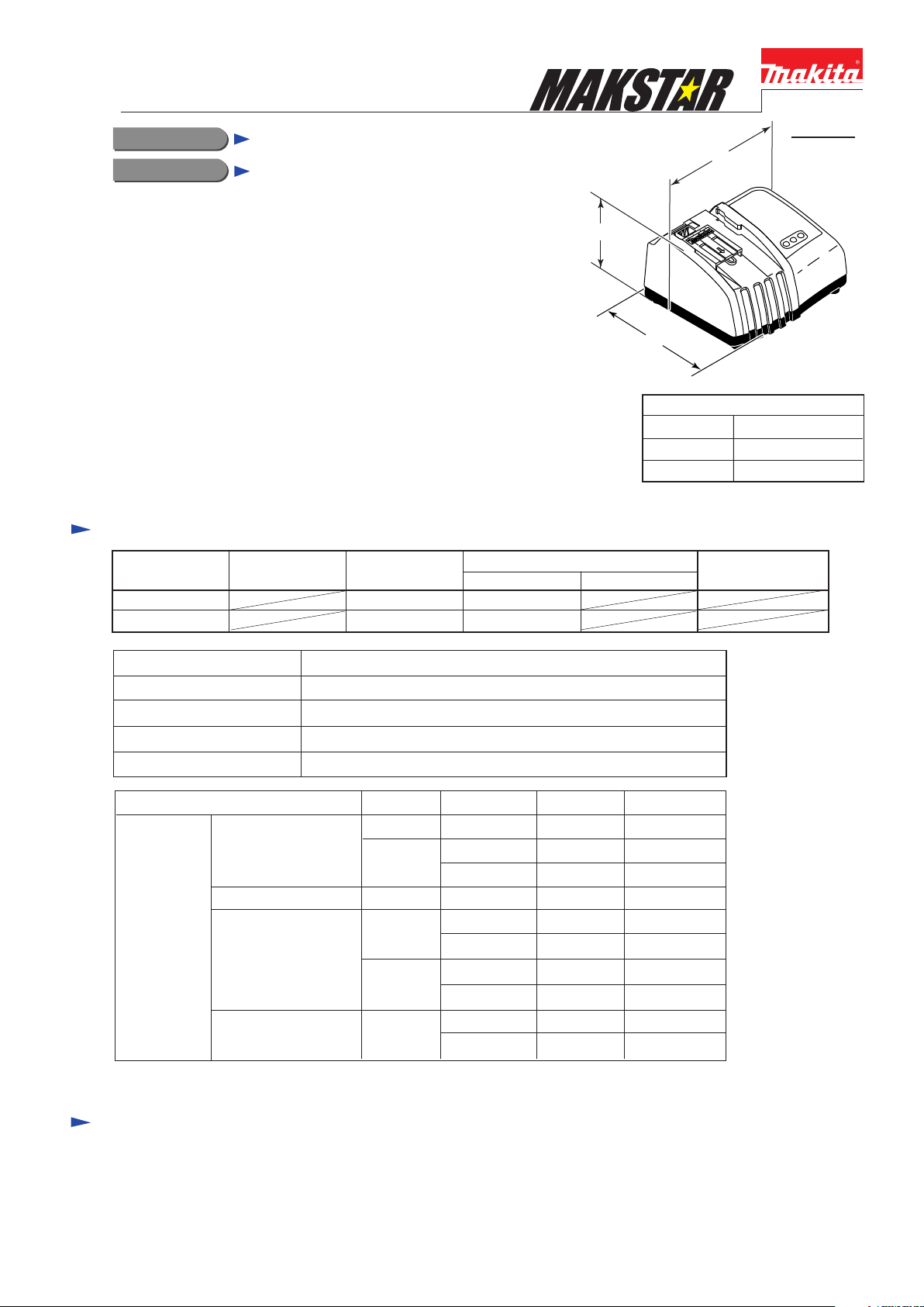
Specification
H
W
L
Dimensions: mm (")
Length (L)
Width (W)
Height (H)
PRODUCT
P 1 / 5
164 (6-1/2)
190 (7-1/2)
106 (4-3/16)
Voltage (V) Cycle (Hz)
110-120
220-240
Output voltage : V
Output current : A
Power Supply Cord: m ( ft )
Net weight: Kg (lbs)
Charging
Time
Current (A)
Approx. 15 min.
Approx. 20 min.
Approx. 22 min.
Approx. 30 min.
50 - 60
50 - 60
Cell Voltage: VCapacity: Ah
Li-ion BL1815
Ni-MH
Ni-MH
Li-ion
Ni-MH
Ni-MH
Continuous Rating (W)
Input Output
240
240
DC 7.2 - 18
DC 9.0
YesDouble Insulation
2.0 (6.6)
1.0 (2.2)
1.5
2.0
2.0
2.0
3.3
18
14.4
12
9.6
183.0
14.43.0
12
14.43.3
9.6 BH90333.3
9.6
Max. Output(W)
Battery
BH1420
BH1220 / C
BH9020 / A
BL1830
BL1430 / A
BH1233/ C
BH1433
BH9033A3.3
< Note > The above figures about charging time may differ from condition to condition on batteries' temperature
or room temperature.
Optional accessories
* ADP03 Automatic Refreshing Adapter
* ADP04 Interchangeable Adapter
Repair
CAUTION: Disconnect the charger from the power source for safety
before repair/ maintenance !
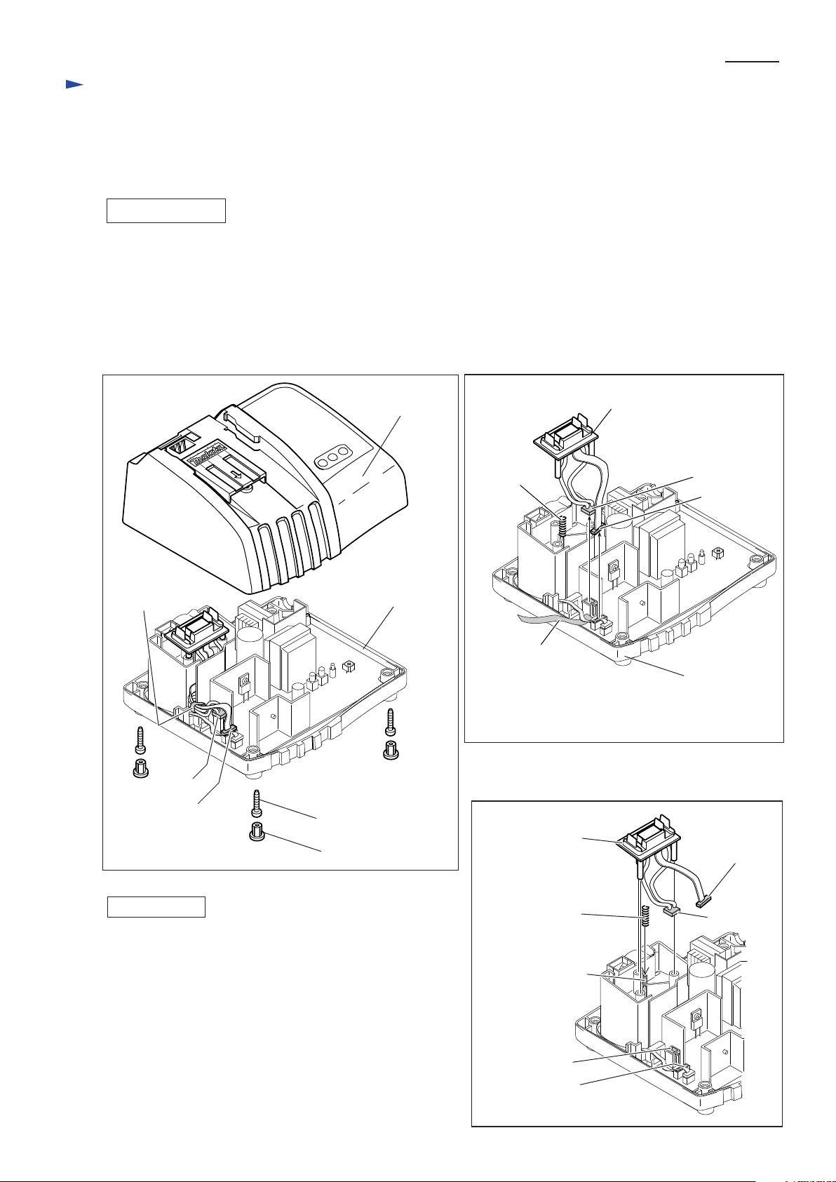
[1] DISASSEMBLY/ASSEMBLY
[1] -1. Terminal Unit
DISASSEMBLING
1. Remove four caps 13 and four 4x20 tapping screws. Consequently, charger case complete can be separated
from charger case cover. (Fig. 1)
< Note >
When removing charger case complete from charger case cover, be sure to put the product on the work bench, with
charger case complete faced to the upper side.
2. Loosen band with which bundles lead wires of terminal unit and that of cirocco fan. Disconnect connector 1 and
connector 2, and remove terminal unit from charger case cover. (Fig. 2)
Fig. 1 Fig. 2
P 2 / 5
Band
Connector 1
Connector 2
Charger Case
Complete
Charger Case
Cover
Tapping
Screw 4x20: 4 pcs.
Cap 13: 4 pcs.
Compression
Spring 4
Fig. 3
Terminal Unit
Terminal Unit
Connector 1
Connector 2
Band
Charger Case
Cover
Connector 2
ASSEMBLING
1. Insert compression spring 4 over the boss for accepting
the compression spring. (Fig. 3)
2. Insert three legs of terminal unit into the three bosses
of charger case cover. (Fig. 3)
3. Connect the connector 1 to the joint for connector 1 and
connector 2 to the joint for the connector 2. (Fig. 3)
4. Bundle the lead wires with band. Refer to Fig. 1.
5. Put the lead wires by the rib and wall of charger case cover
as instructed [2] Wiring Diagram in page 5.
6. Assemble charger case complete with four 4 x20 tapping
screws and four caps 13 firmly.
Compression
Spring 4
Boss for accepting
the compression
spring
Joint for
the connector 1
Joint for
the connector 2
Connector 1
 Loading...