

Makita Makstar BSS610 Technical Information
T
ECHNICAL INFORMATION
Models No.
BSS610
PRODUCT
P 1 / 7
Description
Cordless Circular Saw 165mm (6-1/2")
CONCEPT AND MAIN APPLICATIONS
Model BSS610 has been developed as our first cordless circular saw that is
powered by 18V/3.0Ah Li-ion battery.
Main features are:
Powerful 360W maximum output, yet still with the extra-lightweight and
compact design achieved by using Lithium-ion battery as power unit
Smooth and powerful cutting at the high rotational speed of 3,700 rpm
delivered from enhanced motor
Easy to trace cutting line with:
a) LED job light
b) Built-in blow-off nozzle that directs sawdust away from cutting line
This new product will be available in the following variations.
Model No.
BSS610SF
BSS610SFE*
BSS610Z No
*Offered as Model BSS610 to USA, Canada, Mexico, and Panama
Battery
type quantity
BL1830
No
1
2
Charger
DC18SC
No
Blade
Yes
carrying case
Plastic
Yes
No
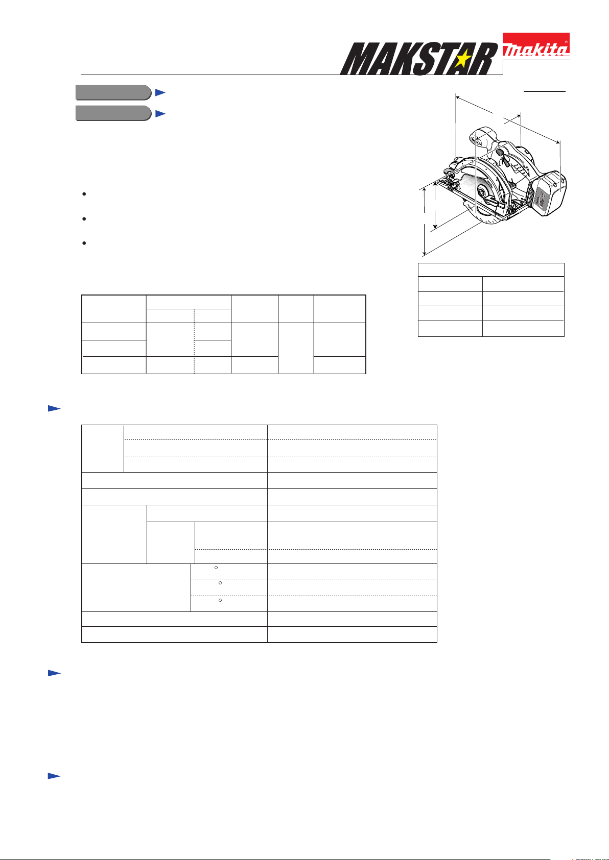
H2
H1
Dimensions: mm (")
Length (L)
Width (W)
Height 1 (H1)
Height 2 (H2)
L
W
347 (13-5/8)
202 (8)
228 (9)
166 (6-1/2)
Specification
Voltage: V
Battery
Max output (W) 360
No load speed: min-1=rpm
Size of blade:
mm (")
Max cutting capacities:
mm (")
Electric brake
Net weight*: kg (lbs)
*Includes battery BL1830
Capacity: Ah
Cell
Diameter
Hole
diameter
Canada, USA,
Mexico, Panama
The others
at 0 57 (2-1/4)
at 45
at 50
18
3.0
Li-ion
3,700
165 (6-1/2)
15.88 (5/8)
20 (13/16)
40 (1-9/16)
36 (1-7/16)
Yes
3.2 (7.1)
Standard equipment
TCT Saw blade 165mm (6-1/2") .................................. 1 pc
Hex wrench 5 ................................................................ 1 pc
Guide rule ..................................................................... 1 pc
Dust nozzle ( exclusively for European countries) ....... 1 pc
Plastic carrying case .................................................... 1 pc
Note: The standard equipment for the tool shown above may differ from country to country.
Optional accessories
Charger DC18SC
Charger DC24SA
Charger DC24SC
TCT Saw blade 165mm (6-1/2")
Li-ion battery BL1830
Repair
CAUTION: Remove Saw blade, Inner flange 40, Outer flange 40, Hex socket head bolt and
Battery cartridge from the machine for safety before repair/ maintenance !
[1] NECESSARY REPAIRING TOOLS
P 2 / 7
Makita Part No.
1R003 Retaining ring pliers ST-2N
1R026 Bearing setting pipe 16-8.2
1R208 90 Degree set square
1R232 Pipe 30
1R263 Bearing extractor
1R269 Bearing extractor
1R291 Retaining S & R pliers
1R340 Bearing retainer wrench
Descriptions Purpose
Removing / Mounting retaining ring
Removing helical gear 52
Adjusting the right angle of saw blade to base plate
Holding bearing box, when removing helical gear 52
Bearing extractor
Bearing extractor
Removing / Mounting retaining ring
Removing / Mounting bearing retainer
Triangular rule
Adjust the saw blade's angle of 45 degree to base plate
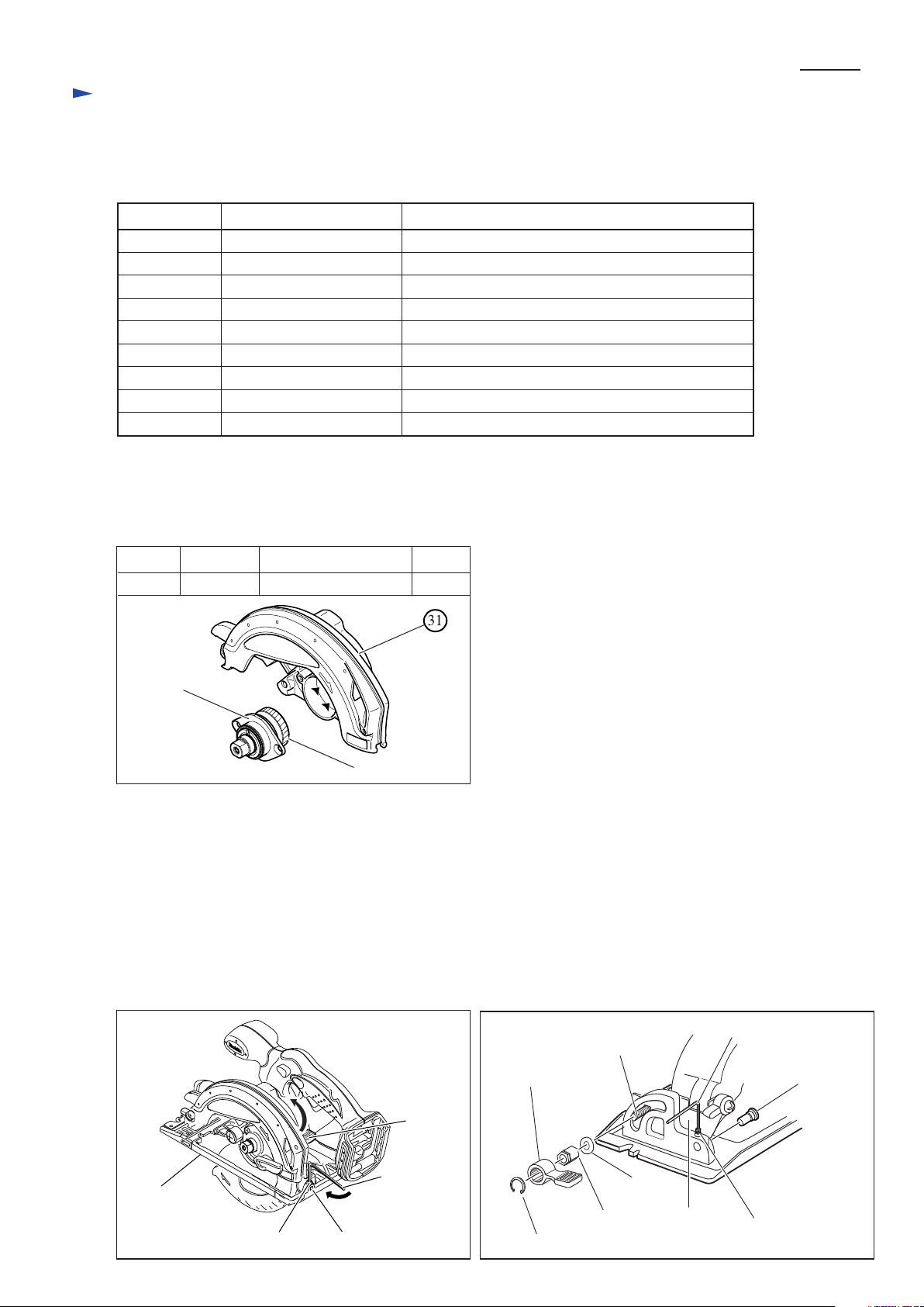
[2] LUBRICATION
Put Makita grease N. No.1 into the gear room indicated by the black triangle to protect parts and product from unusual
abrasion. See Fig.1.
Fig.1
Item No. Parts item Portion to be lubricated
31 Blade case
Gear room
Amount
6g
Bearing box
Helical gear 52
[3] Replacing Base complete
1. Loosen M5x6 Hex socket head set screw for fixing Depth guide to Base complete. See Fig.2.
Loosen Lever 40 and remove Shoulder pin 6-7 for connecting Depth guide and Base complete.
2. Remove the following parts as shown in Fig.3. Base complete can be separated from the machine.
A) Shoulder pin 6-7 for connecting Angular guide and Base complete
B) Stop ring E-8, M6 Hex nut, Flat washer 6 and M6x20 Cap square neck bolt for securing Lever 30
3. Reuse the above parts (for example, Mx6 Hex socket head screws) to replace the current base complete by the new one.
Note: M6 Hex nut in Lever 30 is not interchangeable with M6 Hex nut in Lever 40.
The former has left handed threads, the latter has right handed threads.
Fig. 2
Lever 40
Fig. 3
Lever 30
Cap square
neck bolt M6x20
Hex wrench
Shoulder pin 6-7
Base complete
Hex. wrench
M5x6 Hex socket set screw Shoulder pin 6-7
Stop ring E-8
Flat washer 6
Hex nut M6
Angular guide
Hex socket head
set screw M5x6
Repair
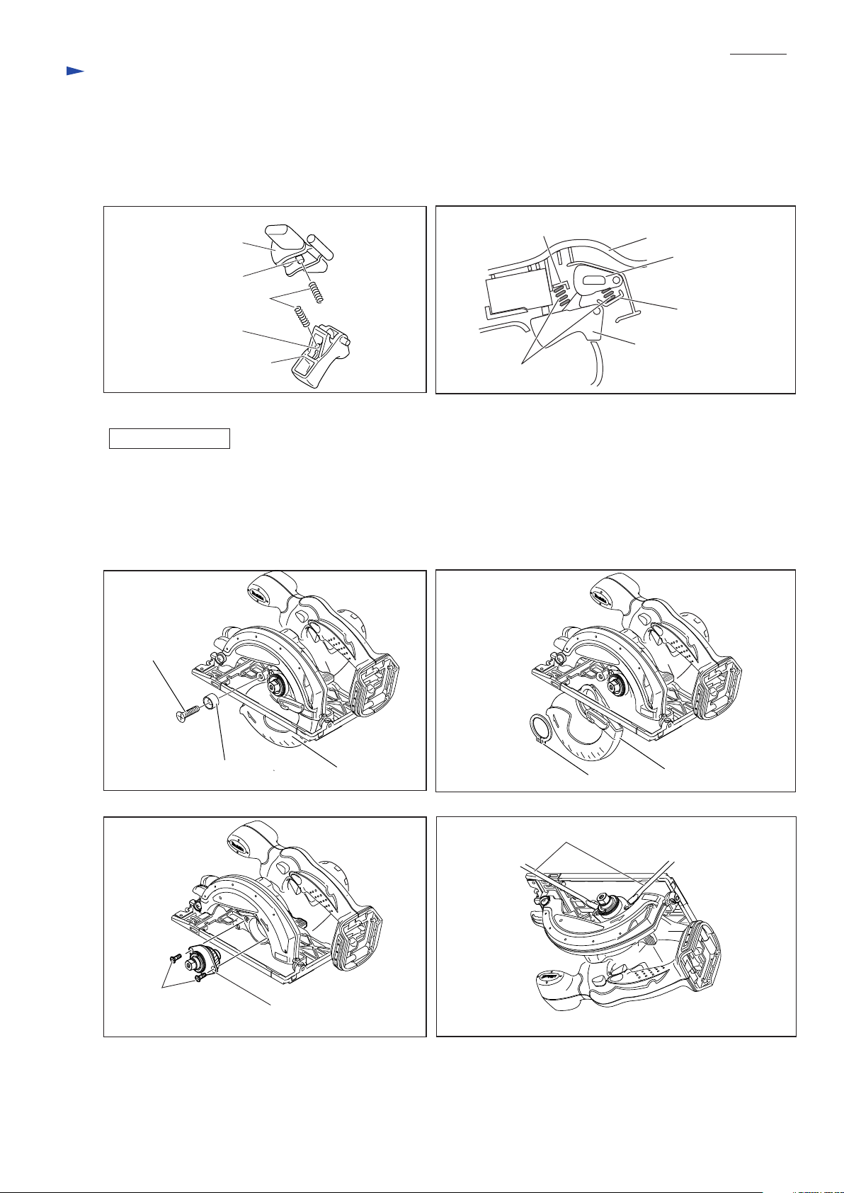
[4] Assembling Lock Off Lever and Switch Lever
1. Compression spring 4 for Lock off lever and Compression spring 4 for switch lever are the same.
Insert the bosses of Lock off lever and Switch lever into the compression springs 4 as illustrated in Fig.4.
2. Put their assembled parts into places as illustrated in Fig.5 so that the Compression springs 4 can perform well
between the bosses and the Ribs of Housing L.
Fig.4
Fig.5
P 3 / 7
Housing L
Lock Off lever
Rib
Switch lever
Lock off lever
Boss
Compression spring 4
Boss
Switch lever
Rib
Switch
Compression spring 4
[5] Disassembling/Asssembling Safety Cover and Bearing Box (Gear Section)
DISASSEMBLING
1. Remove Rubber ring 6 together with M6 countersunk head screw as illustrated in Fig.6.
2. Remove retaining ring S-34 with No.1R003 "Retaining pliers ST-2N". Safety cover can be separated from the machine
as illustrated in Fig.7.
3. Remove Bearing box by unscrewing two M5x16 countersunk head screws as shown in Fig.8. If it is difficult to remove
the Bearing box by hand, lever it up with 1R263 "Bearing extractor" as shown in Fig.9.
Fig.7Fig.6
Countersunk
head screw M6
Fig. 8
Countersunk head
screw M5x16
Rubber ring 6
Bearing box
Safety cover
Fig. 9
Retaining ring S-34
1R263 Bearing extractor
Safety cover
 Loading...