

Makita Makstar BJV140, Makstar BJV180 Technical Information
Models No.
Description
PRODUCT
CONCEPT AND MAIN APPLICATIONS
Specification
Standard equipment
Optional accessories
P 1 /13
Note: The standard equipment for the tool shown above may differ by country.
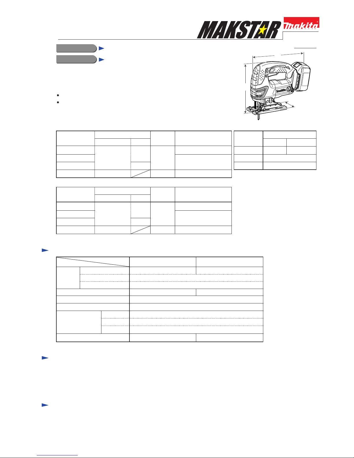
BJV140, BJV180
Cordless Jig Saw
Models BJV140 and BJV180 are MAKSTAR cordless jig saws powered by
3.0Ah Li-ion battery, featuring;
Compact and lightweight design
The same mechanism as used for the popular AC jig saw Model 4340FCT
Jig saw blade assortment ......... 1 set*3
Cover plate ............................... 1 pc
Anti-splintering device ............ 1 pc
Hex wrench 4 ........................... 1 pc
Dust nozzle .............................. 1 pc (for European countries only)
Plastic carrying case ................ 1 pc
Jig saw blades
Guide rule set
Guide rail
Guide rail adapter set
Anti-splintering device
Hose complete 28-5
Dust nozzle
Battery BL1430 (for BJV140 only)
Battery BL1830 (for BJV180 only)
Fast charger DC18RA
Charger DC18SC
Charger DC24SA (for North America only)
Charger DC24SC (for all countries except North America)
Battery
Specification
Net weight*2: kg (lbs)
Capacity: Ah
Cell
Voltage: V
18
No load speed: strokes per min.
SteelCapacities: mm (")
Wood*1
10 (3/8)
Aluminum 20 (25/32)
135 (5-5/16)
2.8 (6.1)
14.4
2.7 (5.9)
3.0
Li-ion
250 340
0 - 2,600
Length of stroke: mm (") 26 (1)
*1 when cutting with optional blade No.B-16L *2 with battery
Max output (W)
Model
BJV140 BJV180
L
H
W
Dimensions: mm (")
Width (W)
Height (H)
Length (L) 255 (10) 257 (10-1/8)
BJV140 BJV180
73 (2-7/8)
208 (8-3/16)
T
ECHNICAL INFORMATION
These products available in the following variations.
All models also include the accessories listed below in "Standard equipment".
BJV140
BJV140RFE
BJV140Z
BJV140
BL1430
(Li-ion 3.0Ah)
DC18RA
No No
Model No.
type quantity
Charger Offered to
All countries
North America
All countries other than
North America
2
BJV140RF 1
Battery
BJV180
BJV180RFE
BJV180Z
BJV180
BL1830
(Li-ion 3.0Ah)
DC18RA
No No
Model No.
type quantity
Charger Offered to
All countries
North America
All countries other than
North America
2
BJV180RF 1
Battery
(Illustrated above is BJV180.)
*3 includes each 2 pcs of B-10, BR-13, B-22
P 2 /13
[1] NECESSARY REPAIRING TOOLS
CAUTION: Remove the jig saw blade from the machine for safety before repair/ maintenance,
in accordance with the instruction manual!
Repair
1R235 Round bar for arbor 6-100
Locking Crank complete when removing/fastening
M4x12 Hex socket head bolt
1R291 Retaining ring S and R pliers
Removing/installing Retaining ring S-8 from/on the shaft portion
of Gear housing Complete
1R220 Ratchet head 9.5
1R222 Socket adaptor
1R254 Torque wrench shaft 2-6N.m
Removing/fastening M4x12 Hex socket head bolt from/to Crank complete
A-33750 Bit adaptor assembly
1R228* 1/4 Hex shank bit M4
1R311 Retaining ring pliers Removing/installing Retaining ring R-18 from/on Blade holder
DescriptionCode No. Use for
Fig. 1
Linear guide Groove portion where 28 Slider slides
Seal plate
Seal plate
Retainer
Blade holder
Gear housing cover complete
Needle bearing 407
Gear complete
Crank complete
Balance plate
Push plate
Gear housing complete
Push pin Whole surface
Surface that contacts Gear housing cover complete
Surface that contacts Retainer
Upper, middle and lower portions of gear room
Surface that contacts Seal plate when Push plate moves downward
Inside surface of the large elliptic hole that contacts Gear complete
Each inside surface of the three small elliptic holes that contacts
corresponding pin on Gear housing complete
Slider
Rod
Groove portion where Needle bearing 407 slides
Item No. Description Portion to lubricate
*1R014 (1/4 Hex shank bit M4) can also be used.
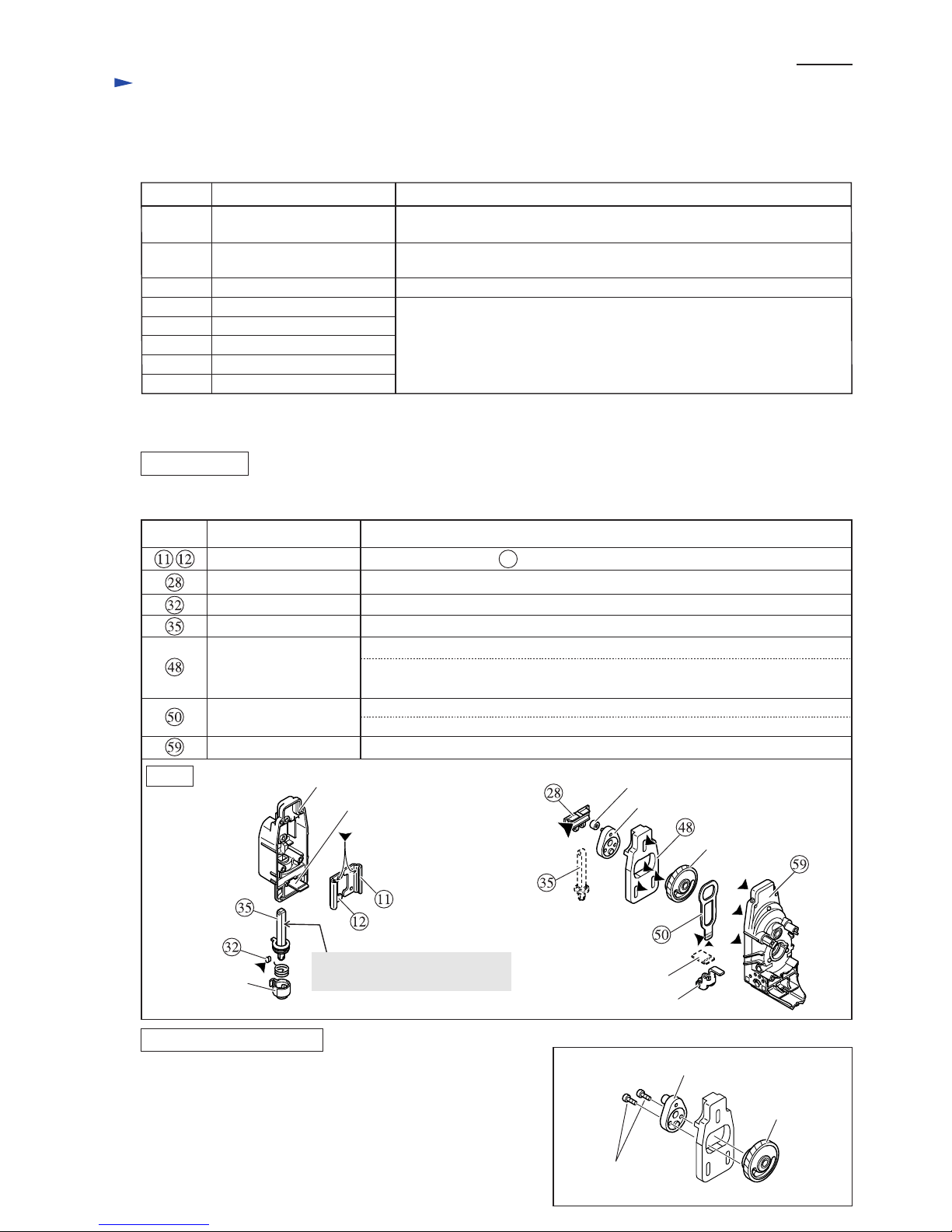
[2] LUBRICATION and ADHESIVE APPLICATION
Apply Makita grease FA. No.2 to the following portions designated with the black triangle
to protect parts and product from unusual abrasion.
If you remove M4x12 Hex socket head bolt from Crank complete,
be sure to apply Loctite 241/242 or Threebond 1321/1342 to the bolt
when reinstalling. (Fig. 2)
LUBRICATION
ADHESIVE APPLICATION
Fig. 2
Gear complete
Crank complete
Hex socket head
bolt M4x12
Apply machine oil #120 here
for smooth reciprocating of Rod.
P 3 /13
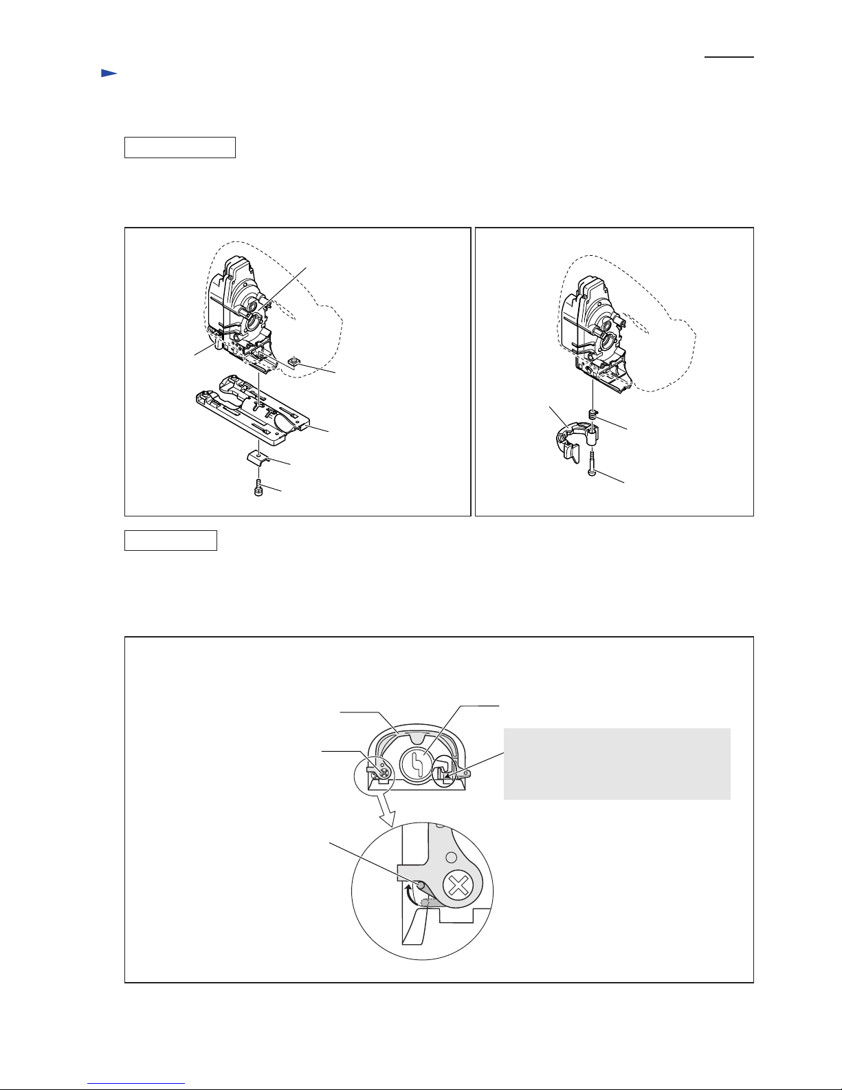
[3] DISASSEMBLY/ASSEMBLY
[3] -1. Tool Opener
Repair
ASSEMBLING
1) Remove Base from Gear housing cover complete by unscrewing M5x18 Hex socket head bolt. (Fig. 3)
2) By unscrewing M4 + Pan head screw, Tool opener can be disassembled from Gear housing cover complete together
with Torsion spring 6. (Fig. 4)
1) Put Torsion spring 6 in the through hole of Tool opener, then fasten Tool opener to Gear housing cover complete
with M4 + Pan head screw. (Fig. 4)
2) Set the end of Torsion spring 6 in place by turning clockwise (viewed from the side of Base) with a small slotted
screwdriver or the like. (Fig. 5)
Tool opener
Torsion spring 6
+ Pan head screw M4
Fig. 3 Fig. 4
Fig. 5
Tool opener assembled to Gear housing cover complete
(viewed from Base side)
Blade holder
Tool opener
end of Torsion spring 6 set in place
Base
Square nut M5-8
Gear housing cover complete
Clamp plate
Hex socket head bolt M5x18
Tool opener
+ Pan head screw M4
Be sure to engage this end of Tool opener
with the hook of Blade holder.
Otherwise, you can not turn Blade holder
with Tool opener when changing blade.
DISASSEMBLING

P 4 /13
[3] DISASSEMBLY/ASSEMBLY
[3] -2. Gear Housing Cover Section
Repair
1) Remove seven Tapping screws that fasten Handle (R) to Handle (L). (Fig. 6)
2) Remove Handles (R) and (L) from Motor housings (R) and (L) as illustrated in Fig. 6A.
3) Separate Gear housing cover section from Gear housing complete by unscrewing four CT4x16 Tapping screws.
(Fig. 7)
Fig. 6
Fig. 7
Tapping screw CT4x16 (4 pcs)
Gear housing cover section
Packing
Gear housing complete
Motor housing (R)
Motor housing (L)
Gear housing
cover section
Gear housing cover section side
Handle (R)
Handle (L)
Motor housing (L)
Fig. 6A
Motor housing (R)
A
Tapping screws that fasten
Handle (R) to Handle (L):
A: Tapping screw 4x18 (5 pcs)
B: Tapping screw 4x40 (1 pc)
C: Tapping screw 4x50 (1 pc)
B
C
A
By pulling Handles (R) and (L)
towards Gear housing cover
section side, each hook portion
of Handles (R) and (L) can be
disengaged from the notch between
Motor housings (R) and (L).
If you are disassembling Gear housing cover section
without removing Tool opener, unscrew this Tapping
screw while opening Tool opener fully.
DISASSEMBLING
 Loading...