

Makita MAKSTAR BJR240SH, MAKSTAR BJR240SF Technical Information
Models No.
Description
PRODUCT
T
ECHNICAL INFORMATION
CONCEPTION AND MAIN APPLICATIONS
Specification
Standard equipment
Optional accessories
< Note > The standard equipment for the tool shown may differ from country to country.
P 1 /15
BJR240
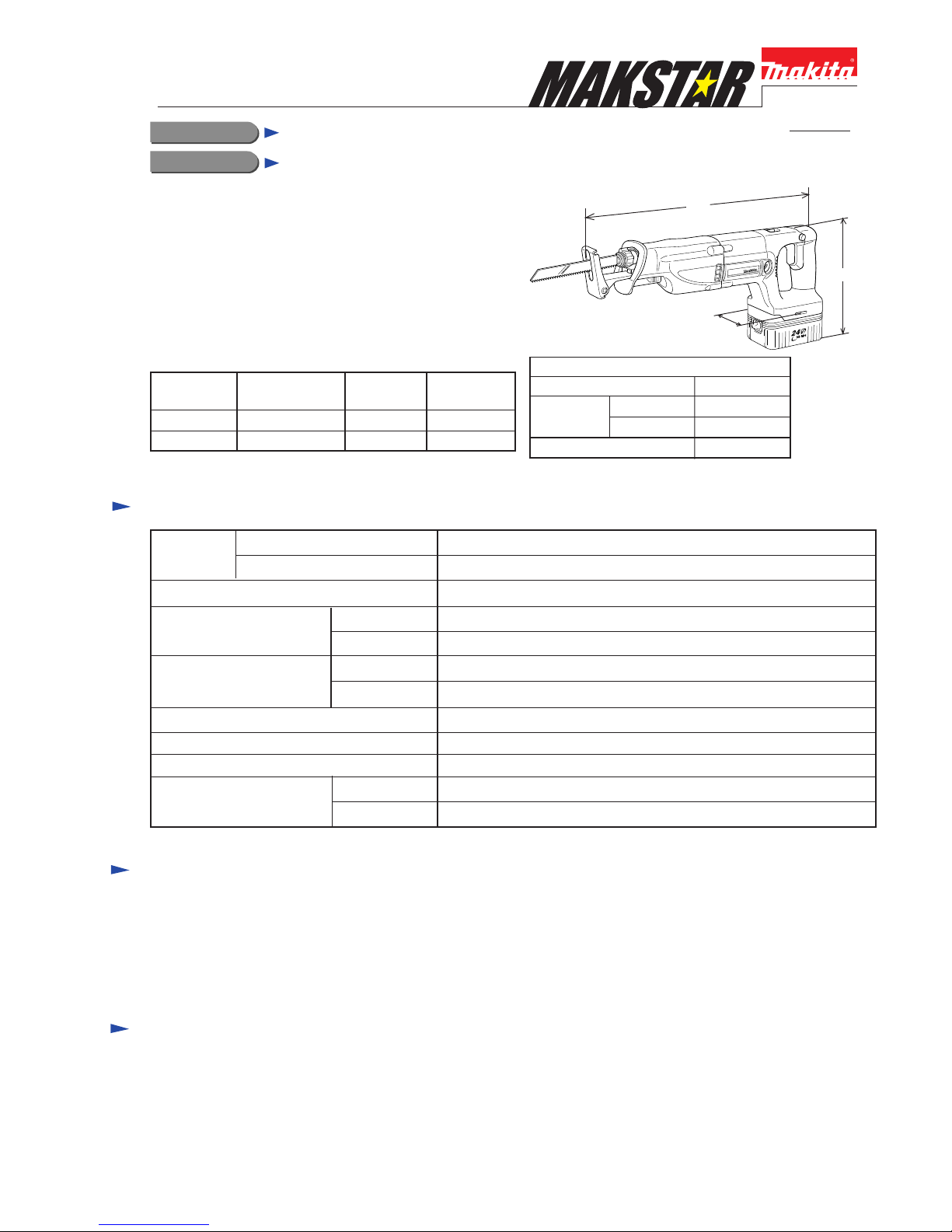
Cordless Recipro Saw
Dimensions : mm ( " )
Width ( W )
Height ( H )
Length ( L )
469 (18-1/2)
230 (9)
255 (10)
88 (3-1/2)
L
W
H
The above model has been developed to be added to MAKSTAR
series models which are featuring New Charging System.
Other features and benefits are
* The fastest cutting speed among the cordless recipro saws
* Incredible low vibration with counterbalancing system
in its gear unit.
* Tool-less features for easy and rapid changing recipro saw blade
and for easy adjusting shoe
The variations of this model are listed below.
w /B2430
w /B2417
Battery
Voltage : V
Capacity : Ah
Length of Stroke
Strokes per Minute
:spm.(min-1)
High
Low
Cutting
capacity: mm (")
Pipe
Wood
Electric brake
Variable switch
Speed change
Net Weight : Kg (lbs)
with B2417
with B2430
32 mm (1-1/4")
0 - 2,700
0 - 2,300
24
4.4 (9.7)
4.9 (10.8)
ø 90 (3-1/2)
90 (3-1/2) in thickness
1.7 with Battery B2417 3.0 with Battery B2430
Yes
Yes
Yes (Electric 2 speed)
Model No.
BJR240SH B2417 (1.7Ah) DC24SA
Battery Charger
Q'ty of
Battery
1 pc.
BJR240SF B2430 (3.0Ah) DC24SA
1 pc.
* Recipro saw blade No.21 for steel ......................... 1 pc.
* Recipro saw blade No.22 for steel ......................... 1 pc.
* Recipro saw blade No.23 for wood ....................... 1 pc.
* Plastic carrying case ............................................... 1 pc
* Various recipro saw blades
* Charger DC24SA
* Battery B2417
* Battery B2430
Features and benefits
P 2 / 15
BJR240
Incredible low vibration with counterbalancing
system in its gear unit.
Model No.
LoadedNo loaded
BJR240 8.7m/sec.2 10.3m/sec.2
Mod. A 11.5m/sec.2 19.8m/sec.2
Mod. B 20.4m/sec.2 20.9m/sec.2
Mod. C 14.4m/sec.2 16.2m/sec.2
Mod. D
8.1m/sec.2 9.4m/sec.2
MAKITA
Lower noise level
Comparison of the specifications
Model No.
LoadedNo loaded
BJR240 82 dB 94 dB
85 dB 94 dB
85 dB
85 dB
94 dB
97 dB
95 dB91 dB
MAKITA
BJR240
MAKITA
The figures on loaded condition are based on
the cutting of chip board 19mm in thickness.
The figures on loaded condition are based on
the cutting of chip board of 19mm in thickness.
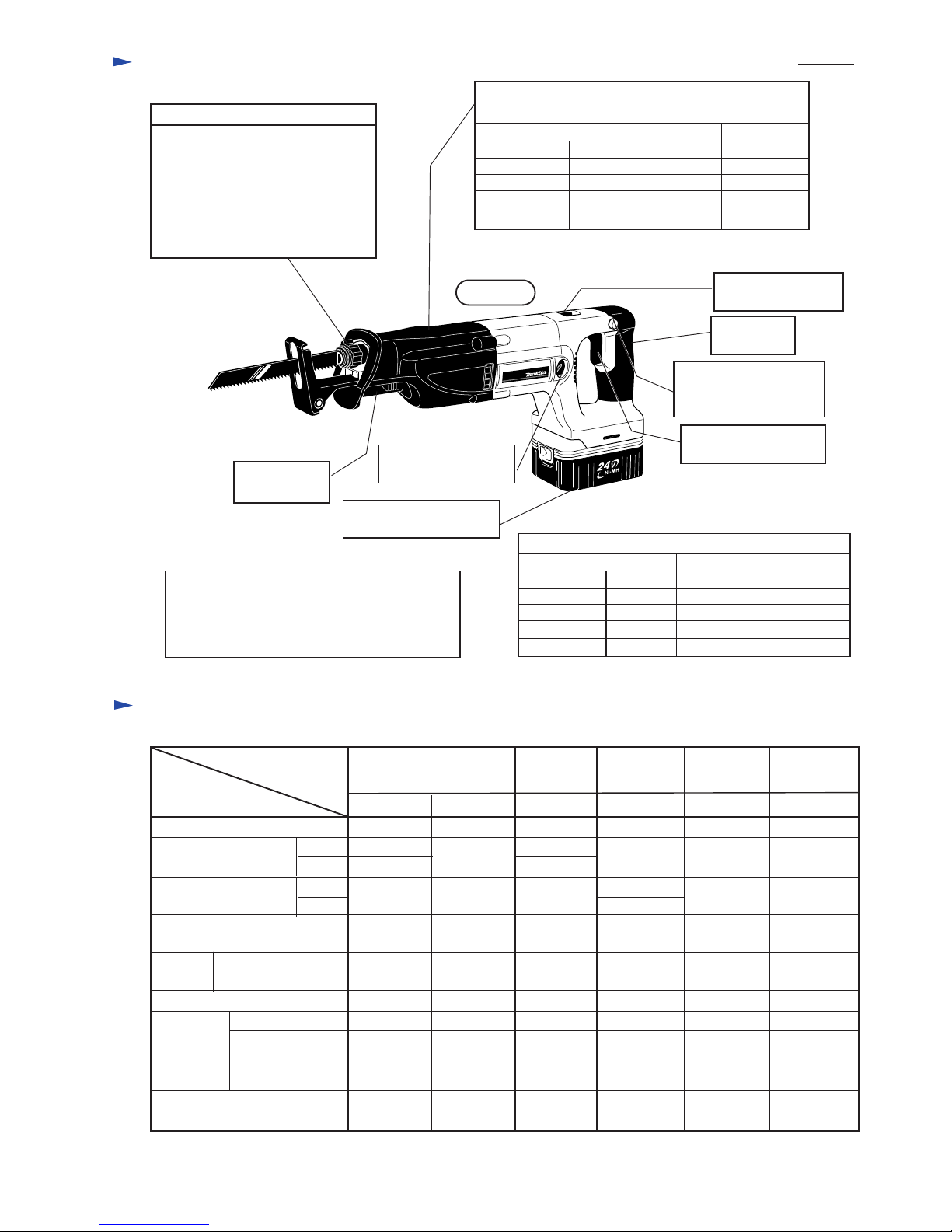
Push-in Lock System has
made it possible to install
the blade quickly.
New tool-less blade change system
Lock off push-out system has
enabled to take off the hot saw
blade of just after work, without
touching it.
Externally accessible
carbon brush
Tool-less shoe
adjustment
Electric High /Low
speed change switch
Palm fitting
soft grip
Lock off button can be
pushed from both of left
and right.
Switch with big trigger
for easy operation
24V Ni-MH Battery with
new charging system
The fastest cutting speed among
the cordless recipro saws.
See the graph in "Comparison of Products"
at page 3.
Comparison of products
Model No.
Specifications
Voltage
Tool-less
system
Length of Stroke
: mm (1-1/4")
Strokes per
Minute :spm.(min-1)
High
Dimensions
including
battery
Weight including
battery :Kg (lbs)
Low
High
Low
Suppressing the vibration
Externally accessible brush
for replacing blade
for adjusting shoe
Palm fitting soft grip
Height : mm(")
Width : mm(")
Length : mm(")
32 (1-1/4)
0 - 2,700
0 - 2,300
24
Yes
Yes
Yes
Yes
Yes
469 (18-1/2)
230 (9)
*255 (10)
88 (3-1/2)
4.4 (9.7)
*4.9 (10.8)
29 (1-1/8) 28 (1-1/8) 25 (1)
0 - 2,900
0 - 2,900
0 - 2,400
24
Yes
Yes
Yes
463 (18-1/4)
232 (9-1/8)
80 (3-1/8)
3.9 (8.6)
JR180D
23 (7/8)
0 - 2,700
18
No No
No
Yes
No
Yes
Yes
NoYes
Yes
Yes
No
447 (17-5/8)
206 (8-7/8)
95 (3-3/4)
3.5 (7.7)
32 (1-1/4)
19 (3/4)
0 - 2,300 0 - 2,600
24 24 19.2
No No
No
No
Yes
Yes
Yes
Yes
Yes
Yes
495 (19-1/2)
213 (8-3/8)
76 (3)
448 (17-5/8)
240 (9-1/2)
83 (3-1/8)
3.9 (8.6) 4.3 (9.5)
393 (15-1/2)
202 (8)
76 (3)
4.5 (9.9)
*255 (10) and *4.9 (10.8) are the data when battery B2430 is attached.
Competitor A
Competitor B
Competitor C
Competitor D
Mod. A
Mod. B
Mod. C
Mod. D
Mod. D
Competitor A
Competitor B
Competitor C
Competitor D
Mod. A
Competitor
A
Competitor
B
Competitor
C
Competitor
D
Mod. B Mod. C
Comparison of products
P 3 / 15
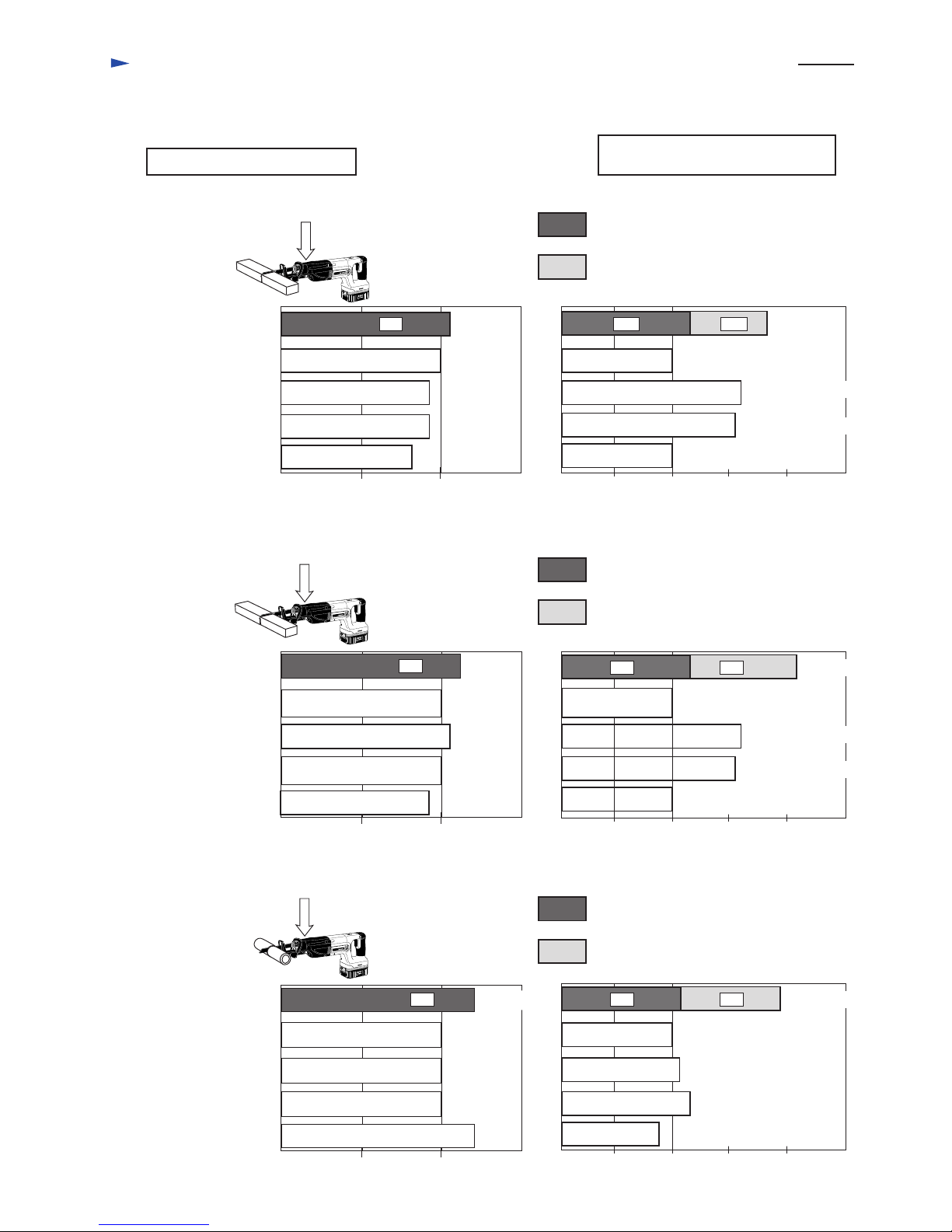
Comparison of the cuting speed
Comparison of the working amount
per one full charged battery pack
Testing conditions
Material : Spruce (Wood) 2" x 10"
Pressure load ; 5 kg.f
Testing conditions
Material : Spruce (Wood) 2" x 10"
Pressure load ; 7 kg.f
Testing conditions
Material : Steel Pipe ø 1"
Pressure load ; 5 kg.f
MAKITA
BJR240
Competitor C
Model C
Model D
Competitor D
Competitor A
Model A
Competitor B
Model B
0 50 100 50 100150 150 200 250
100 100
100
165
160
100
165
160
MAKITA
BJR240
0 50 100 150
100
100
MAKITA
BJR240
0 50 100 150
100
100
100
80
105
95
95
(7.5 sec.)
(5.5 sec.)
110
105
105
95
120
120
Numbers in graph below are relative values when setting capacity of competitor A's model as 100.
(21 sec.)
50 100 150 200 250
100
50 100 150 200 250
100
110
120
80
: Amount with 1.7Ah battery B2417
: Whole amount with 3.0Ah battery B2430
: Amount with 1.7Ah battery B2417
: Whole amount with 3.0Ah battery B2430
: Amount with 1.7Ah battery B2417
: Whole amount with 3.0Ah battery B2430
120
120
110
180
210
195
with 1.7Ah battery
with 1.7Ah battery
with 1.7Ah battery
with 2.0Ah battery
with 2.0Ah battery
with 2.0Ah battery
with 2.0Ah battery
with 2.0Ah battery
with 2.0Ah battery
with 2.0Ah battery
with 2.0Ah battery
with 2.0Ah battery
< Note > The data mentioned below may differ depending on the conditions of batteries' temperature,
room temperature, materials,etc.
27 / 47cuts
29 / 51cuts
11 / 19cuts
Competitor C
Model C
Model D
Competitor D
Competitor A
Model A
Competitor B
Model B
Competitor C
Model C
Model D
Competitor D
Competitor A
Model A
Competitor B
Model B
Repair
P 4 / 15
< 1 > Lubrication
Apply MAKITA grease N No.1 to the following portions marked with black triangle to protect parts and machine
from unusual abrasion. See Fig. 1.
< 2 > Sealing
< 3 > Disassembling and assembling
Apply three bond 1215 to the following portion of gear housing cover which joins to gear housing, when assembling.
See Fig. 2.
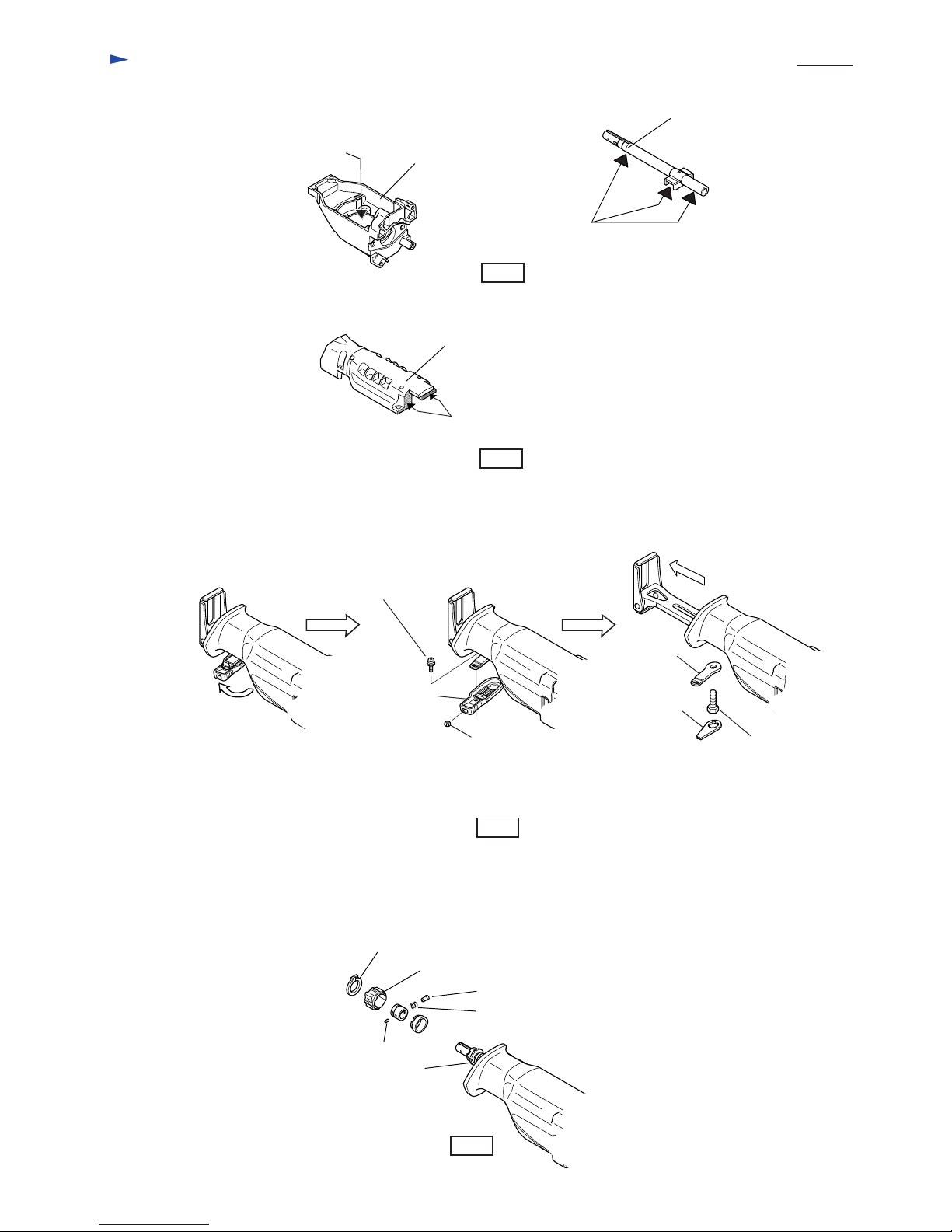
(1) Removing shoe
Turn lever 60 (adjusting lever for shoe), and take off pan head screw M4x10. Then, lever 60 can be removed.
Take off hex bolt M8x25 (This hex bolt can be unscrewed by using lock lever as a wrench.), and inner plate.
Remove shoe by pulling out. See Fig. 3.
(2) Disassembling blade clamp section
Remove shoe as mentioned above. Pull out the blade clamp section, if it stays near gear housing.
1. Take off retaining ring S-18 with No.1R291 "Snap ring plier".
2. Take off driving sleeve, shoulder pin 5, compression spring 6,
pin 3, guide sleeve and driving sleeve guide from slider.
Apply 7g.
Slider
Apply 12g.
Gear housing
Apply here three bond 1215
for sealing.
Gear housing cover
Fig. 1
Fig. 2
Fig. 3
Fig. 4
Turn lever 60
(adjusting lever for shoe).
Take off pan head screw M4x10.
<Note> Be careful, not to lose
hex nut M4 in lever 60.
Pan head screw
M4x10
Lever 60
Hex nut M4
Lock lever
Inner plate
Hex bolt M8x25
Pull out shoe.
Retaining ring S-18
Driving sleeve
Compression spring 6
Shoulder pin 5
Pin 3
Sleeve
Repair
P 5 / 15
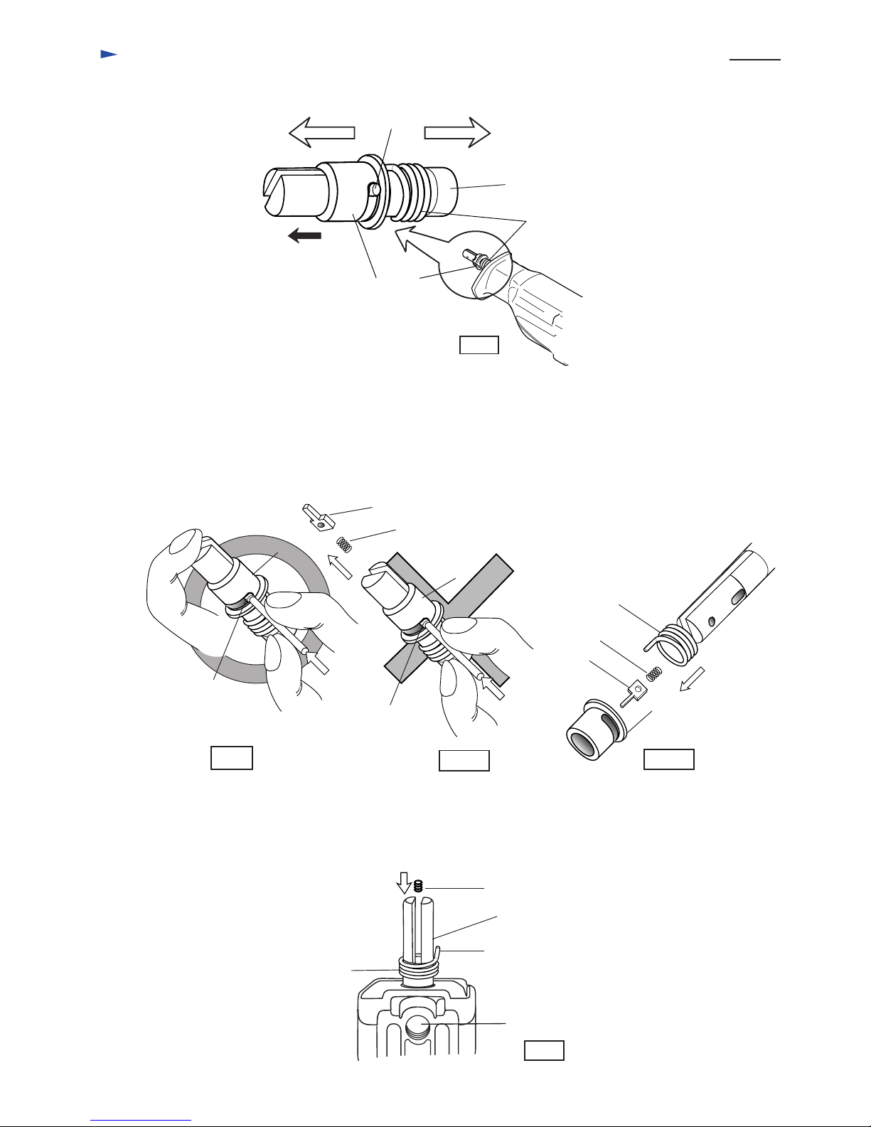
3. Sleeve is in the lock position. In order to free from lock position, pull sleeve toward the blade installing side.
(When the sleeve is free from lock, pin 3 (long) is at the position illustrated in Fig. 5.
4. Holding the top of slider with your finger, remove sleeve by pushing pin 3 (long) with a small sticker
through slider as illustrated in Fig. 6.
< Note > When removing sleeve, always hold the top of slider with your finger as illustrated in Fig. 6.
Otherwise, push plate and compression spring 2 can spring out from slider as illustrated in Fig. 6A,
and they will get lost.
After removing sleeve, take off push plate, compression spring 2 and torsion spring 17 from slider
as illustrated in Fig. 6B.
Fig. 5
Sleeve
Pin 3 (long)
Torsion spring 17
Slider
Blade installing side
Gear housing side
Pull the sleeve to this
direction.
Fig. 6
Fig. 6A
Push plate
Compression spring 2
Fig. 6B
Torsion spring 17
Compression spring 2
Push plate
Sleeve
Sleeve
Pin 3
Pin 3
Sleeve
(3) Assembling blade clamp section
1. Assemble torsion spring 17 to slider. And then, set compression spring 2 into slider.
<Note> Pay attention to the position of the tail of torsion spring 17. It has to come to the right side
in the view from the side of shoe adjusting bolt M8x25, as illustrated in Fig. 7.
Torsion spring 17
Slider
The tail of
torsion spring 17
Compression spring 2
Threaded hole for hex bolt M8x25
Fig. 7
 Loading...