

Makita BTD129, LXDT08 Series Technical Information
Models No.
Description
PRODUCT
CONCEPT AND MAIN APPLICATIONS
P 1/ 12
BTD129 (LXDT08)*1
Cordless Impact Driver
Specification
Standard equipment
Optional accessories
Note: The standard equipment for the tool shown above may vary by country.
See the model variation list in the next page.
Model BTD129 (LXDT08*
1) Cordless Impact Driver has been developed specially for
light to medium duty fastening applications.
This model is equipped with a basic BLDC motor (BrushLess DC motor) specially
designed to provide, above all, more work amount on a single full battery charge.
This product is powered by 18V-1.3(1.5*4)Ah/ 3.0Ah Li-ion batteries BL1815/ BL1830,
and available in the variations listed in the next page.
Battery
No load speed: min.
ˉ¹=rpm
Impacts per min.: min.
ˉ¹=ipm
Max. fastening torque
*5:
N.m (kgf.cm/ in.lbs)
Charging time (approx.): min.
Capacities
Electric brake
Reverse switch
Weight according to
EPTA-Procedure 01/2003: kg (lbs)
Variable speed control by trigger
Capacity: Ah
Cell
Voltage: V
18V
0 - 2,500
0 - 3,200
160 (1,630/ 1,420)
Standard bolt
High tensile bolt
Machine screw
Driving shank
M5 - M14 (3/16 - 9/16")
M5 - M12 (3/16 - 1/2")
Coarse thread screw
22 - 125mm (7/8 - 4-7/8")
M4 - M8 (5/32 - 5/16")
Yes
Yes
Yes
LED job light
Yes
1.3 (2.9)/ 1.5 (3.4)
1.3 (1.5*
4)/ 3.0
Energy capacity: Wh
24 (2.7*
4)/ 54
Li-ion
220
15/ 22 with DC18RC (DC18RA*
4)
6.35mm (1/4") Hex
Max output (W)
*
4 for some countries only
*5 The fastening torque at 3 seconds after seating, when fastening M14 high tensile bolt
*
1 Model number for North and Central American countries
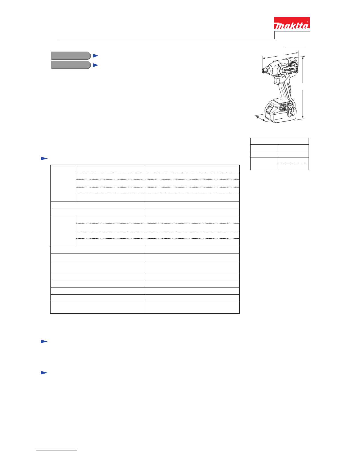
H
W
Dimensions: mm (")
Width (W)
Height (H)
Length (L)
147 (5-7/8)
79 (3-1/8)
226 (8-7/8)*
2
244 (9-5/8)*3
*2: with Battery BL1815
*3: with Battery BL1830
Phillips bits
Socket bits
Drill chucks
Bit piece
Hole saws for Impact driver
Stopper for Impact driver
Hook set (Belt clip)
Drill bits with 6.35mm Hex shank
Battery protectors
Li-ion Battery BL1830
Li-ion Battery BL1815
Fast charger DC18RA
(for USA, Canada, Guam, Panama, Colombia, Mexico)
Fast charger DC18RC
(for all countries except the countries above)
Charger DC18SD
Charger DC24SC
Automotive charger DC18SE
L
[Drawn above is the image
with BL1830.]
T
ECHNICAL INFORMATION
P 2/ 12
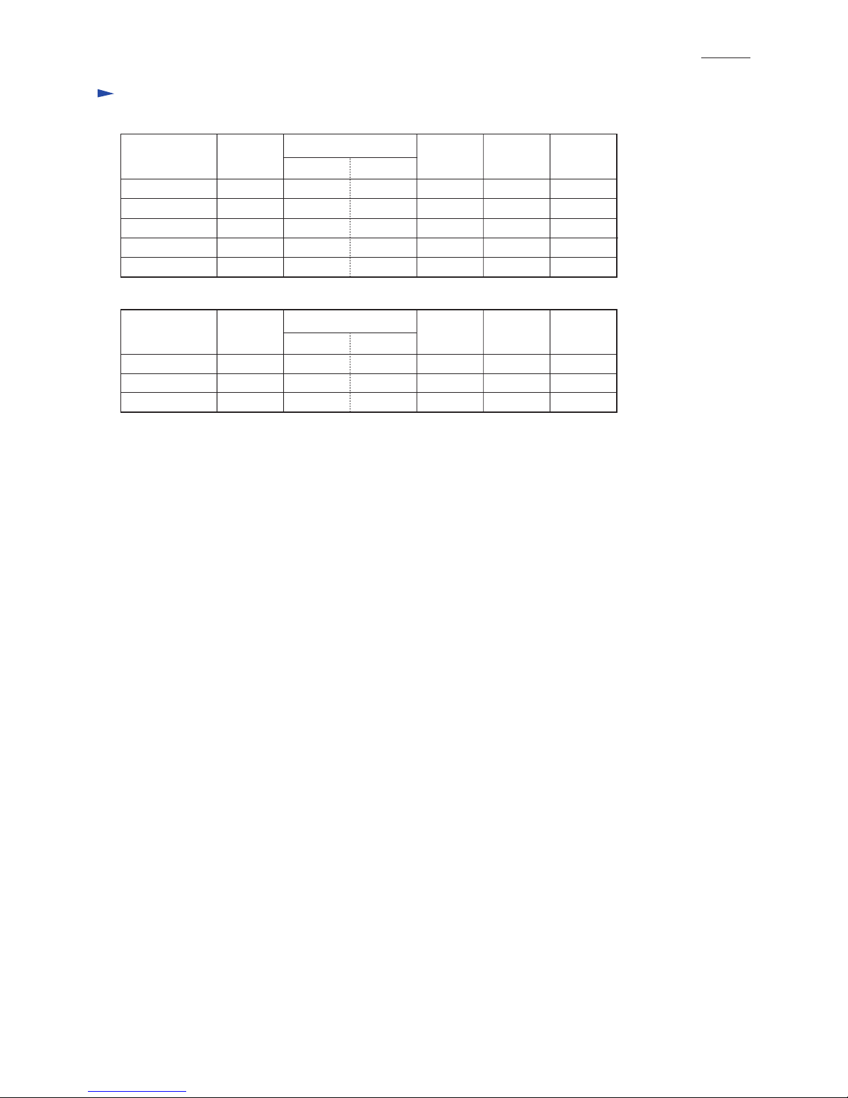
Variation list
BTD129RFE
BTD129RHE
Model No.
Type Quantity
Plastic
carrying
case
Battery
cover
Battery
No NoBTD129Z No
2 1
No
Yes
Yes
Yes
DC18RC
Charger
No
No YesNo NoNo
YesBL1830 Yes
Yes
Yes
2 1DC18RC
BTD129ZK
BL1815
BTD129SHE 2 1 YesDC18SD BL1815
BTD129
Model No.
Quantity
Battery
LXDT08Z NoNoNo No Yes
LXDT08 Yes2BL1830 1 Yes
Yes
No
DC18RA
LXDT08C1 Yes2BL1815 1DC18SD
*1 Model number for North and Central American countries
LXDT08*
1
Belt
clip
Type
Plastic
carrying
case
Battery
cover
Charger
Belt
clip
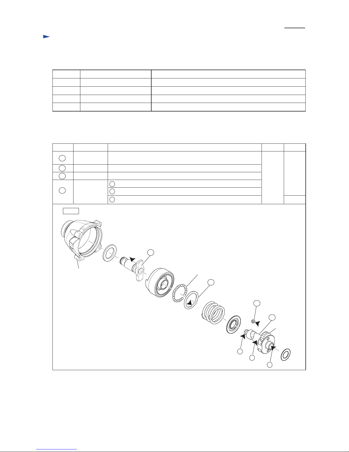
Repair
Apply Makita grease FA No.2 to the following portions indicated by the black triangle to protect
parts and product from unusual abrasion.
[1] NECESSARY REPAIRING TOOLS
CAUTION: Repair the machine in accordance with “Instruction manual” or “Safety instructions”.
Code No. Description Use for
1R045 Gear extractor (large) Disassembling/ assembling Hammer section
1R232 Pipe 30 Holding hammer case when removing/ assembling Bit holder section
1R288 Screwdriver magnetizer Magnetizing a screwdriver for easy removal of Steel ball 5.6
1R291 Retaining ring S and R pliers Removing/ mounting Ring spring 11 of Bit holder section
[2] LUBRICATION
Fig. 1
DescriptionItem No.
Grease
Makita
FA No.2
AmountPortion to lubricate
2 g
19
Hammer case
Anvil
Flat washer 24
Steel ball 5.6 a little
Drum portion that contacts Sleeve and O ring 14 of Hammer case
complete
Surface that contacts 24 pcs. of Steel ball 3.5
Whole portion
Spur gear 22
Steel ball 3.5
(24 pcs.)
a
c
Insertion hole for Armature for smooth engaging with Spur gear 22
b
Spindle
Tip portion to be inserted into the hole of Anvil
Surface that contacts Hammer
22
19
22
25
25
27
27
a
c
b
P 3/ 12
Repair
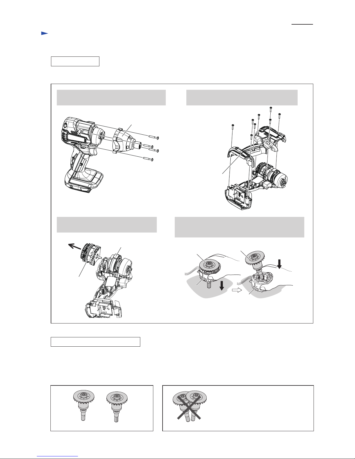
[3] DISASSEMBLY/ASSEMBLY
[3] -1. Rotor
DISASSEMBLING
Fig. 2
Hammer case
complete
1. By unscrewing four 4x25 Tapping screws,
remove Hammer case complete.
2. By unscrewing 8 pcs. of 3x16 Tapping screws,
remove Housing (R).
3. Separate Rotor section (Rotor and Stator)
from Internal gear case complete.
Housing (R)
Disassemble Rotor. (Fig. 2)
4x25 Tapping screw
(4 pcs.)
3x16 Tapping screw
(8 pcs.)
4. Put Rotor section on a workbench so that the drive end
of Rotor touches the workbench.
Press Stator down to separate it from Rotor.
Rotor
Stator
Stator
Rotor
Internal gear case
complete
Rotor section
Caution for Handling of Rotor
Fig. 3R Fig. 3F
* Magnetic loss of Rotors
* Damage on the magnet portion of Rotors
When handling or storing multiple Rotors, be sure to keep a proper distance between Rotors as shown in Fig. 3R because
Rotor has a strong magnet, failure to follow this instruction could result in:
• Finger injury caused by pinching between Rotors pulling each other.
• Magnetic loss of Rotors or damage on the magnet portion of Rotors. (Fig. 3F)
P 4/ 12
 Loading...