

Makita BTD146, LXDT04CW, BTD146RHE, LXDT04, BTD146RFE3 Technical Information
...
Models No.
Description
PRODUCT
P 1/ 11
BTD146 (LXDT04*1)
Cordless Impact Driver
*1 Model number for North and Central American countries
CONCEPT AND MAIN APPLICATIONS
Specification
Standard equipment
Optional accessories
Note: The standard equipment for the tool shown above may vary by country.
Model BTD146 Cordless Impact Driver is an advanced version of Model BTD141,
featuring the same ergonomically designed handle and 4-pole motor as the existing model,
plus more compact design, enhanced dust and drip-proof performance and battery fuel gauge*
2.
This product is powered by 18V/1.3Ah Li-ion battery BL1815 and 18V/3.0Ah Li-ion battery
BL1830.
See the product variation list above.
*5 torque at 3 seconds after seating, when fastening M14 high tensile bolt
*2 This gauge is available for all countries except North and Central American countries
Battery
No load speed: min.-
1=rpm
Impacts per min.: min.-
1=ipm
Max. fastening torque*
5: N.m (kgf.cm/ in.lbs)
Charging time: min.
Capacities
Electric brake
LED job light
Weight according to
EPTA-Procedure 01/2003: kg (lbs)
Variable speed control by trigger
Capacity: Ah
Cell
Voltage: V
18V
0 - 2,300
0 - 3,200
160 (1,630/ 1,420)
Standard bolt
High tensile bolt
Machine screw
Driving shank
M5 - M14 (3/16 - 9/16")
M5 - M12 (3/16 - 1/2")
Coarse thread screw
22 - 125mm (7/8 - 4-7/8")
M4 - M8 (5/32 - 5/16")
Yes
Yes
Yes
Reverse switch Yes
1.3*
3/ 1.5*4 (2.8*3/ 3.3*4)
1.3/ 3.0 (battery BL1815/ BL1830)
Li-ion
220
approx. 15/ 22 with DC18RC or DC18RA
6.35mm (1/4") Hex
This product is available in the following variations.
Phillips bits
Socket bits
Drill chucks
Bit piece
Drill bits
with 6.35mm Hex shank
Hole saws for Impact driver
Stopper for Impact driver
Hook set (Belt clip)
Tool hanger
Battery protectors
Li-ion Battery BL1830
Li-ion Battery BL1815
Fast charger DC18RA
(for North and Central American countries only)
Fast charger DC18RC
(for all countries except North and Central American countries)
Charger DC18SD
Charger DC24SC
Automotive charger DC18SE
Dimensions: mm (")
Width (W)
Height (H)
Length (L)
138 (5-7/16)
79 (3-1/8)
238 (9-3/8)*
4
220 (8-5/8)*3
*3 with Battery BL1815
*4 with Battery BL1830
W
L
H
(with Battery BL1830)
Max output (W)
T
ECHNICAL INFORMATION
BTD146RFE
BTD146Z
LXDT04Z
LXDT04ZW
BTD146RF
LXDT04
LXDT04CW
BTD146RFE3
BL1830
(Li-ion 3.0Ah)
BL1815
(Li-ion 1.3Ah)
No
DC18RC
DC18RC
DC18RA
DC18RA
No
Model No.
type quantity
Charger
Yes
Belt
clip
1
2
No
Battery
cover
Yes
No
Plastic
carrying
case
2
0
1
BTD146RHE
1
2
3
2
No
Battery
Makita-blue
Makita-blue
White
White
Housing
color
1
P 2/ 11
Repair
CAUTION: Repair the machine in accordance with “Instruction manual” or “Safety instructions”.
[1] NECESSARY REPAIRING TOOLS
[2] LUBRICANT
Description
Vise plate removing Hammer case complete
removing Hammer case
removing Hammer case complete
removing Bit holder section
removing Hammer
Code No.
1R041
1R045 Gear extractor (large)
Torque wrench shaft 20-90N·m
Ratchet head 12.7 (for 1R223)
Pipe 30
Socket 30 -78 ass’y
Socket 32 -50 ass’y
Screwdriver Magnetizer
Retaining Ring S and R Pliers removing Ring spring 11 from Bit holder section
1R223
1R224
1R232
1R288
1R291
134847-1
134848-9
Use for
removing Steel balls
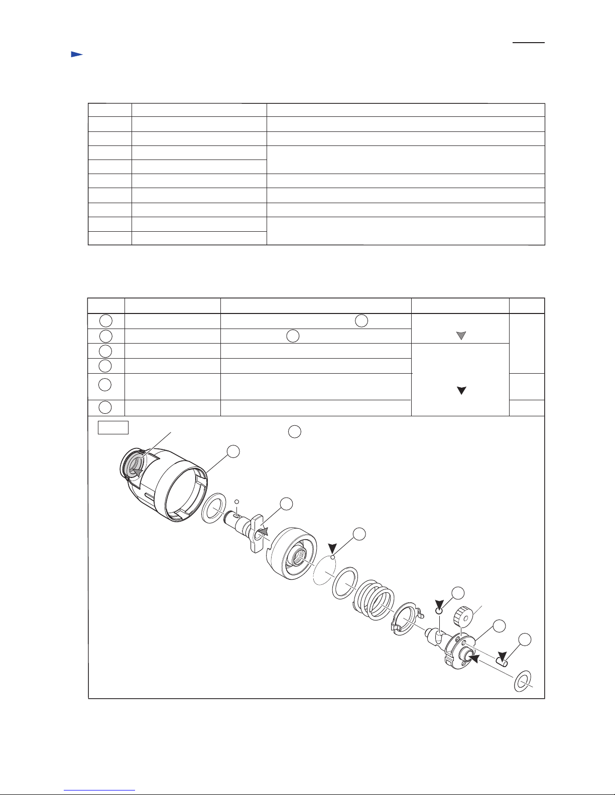
Fig. 1
16
21
25
27
28
Spur gear 22
Apply the following lubricants to protect parts and product from unusual abrasion. (Fig. 1)
Item No. Description
Anvil
Steel ball 3.5 (24pcs.)
Steel ball 5.6 (2pcs.)
Hammer case complete Inside of Sleeve 14 which touches 19
Hole into which 27 Spindle top is inserted
Hole into which Armature's drive end is inserted
to engage Spur gear 22
Whole portion
Whole portion
Whole portion
Portion to lubricate
16
19
21
25
27
Spindle 2g
16
Sleeve 14 (The component of )
28 Pin 5
Lubricant Amount
a little
a little
Makita grease FA. No.2
Makita grease N. No.2
19
[3] DISASSEMBLY/ASSEMBLY
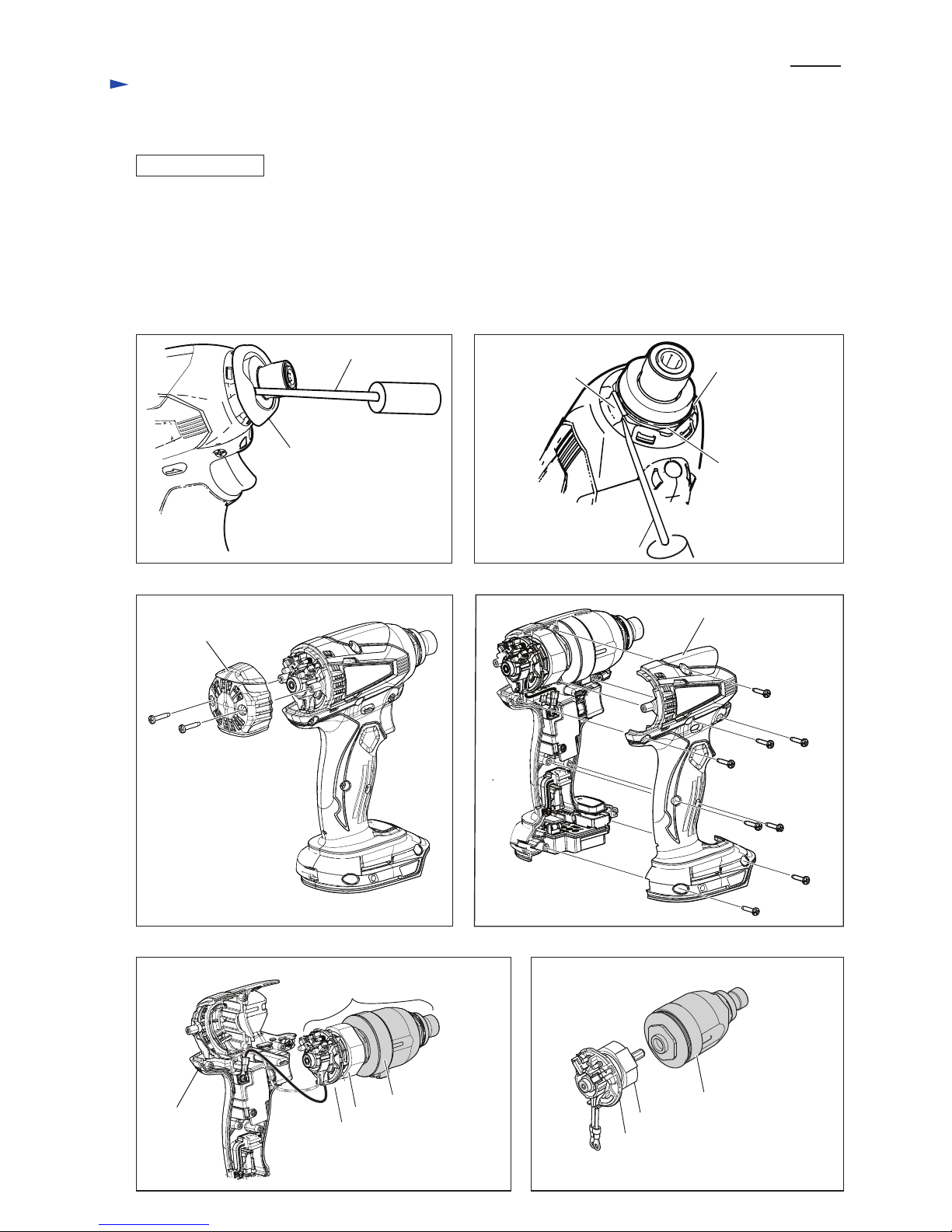
[3]-1. Hammer case complete
DISASSEMBLING
Fig. 2 Fig. 3
Fig. 4
Fig. 6 Fig. 7
Fig. 5
(1) Twist and remove Bumper with slotted screwdriver. (Fig. 2)
(2) While releasing the hooks of Hammer case cover from Hammer case complete carefully, remove Hammer case
cover. (Fig. 3)
(3) Unscrew two 3x16 Tapping screws on Rear cover and remove Rear cover. (Fig. 4)
(4) Unscrew eight 3x16 Tapping screws on Housing set (R) and then remove Housing set (R). (Fig. 5)
(5) Remove an assembled part consists of three sections from Housing set (L). (Fig. 6)
(6) Pull out Hammer section from the other sections. (Fig. 7)
Rear cover
Bumper
hook of Hammer
case cover
hook of Hammer
case cover
Hammer
case complete
Slotted screwdriver
Slotted screwdriver
3x16 Tapping
screw (2pcs.)
3x16 Tapping
screw (8pcs.)
Housing set (R)
Housing
set (L)
Hammer section
An assembled part consists
of three sections.
Motor section
Brush holder section
Motor section
Brush holder section
Hammer section
P 3/ 11
Repair
[3] DISASSEMBLY/ASSEMBLY
[3]-1. Hammer case complete (cont.)
DISASSEMBLING
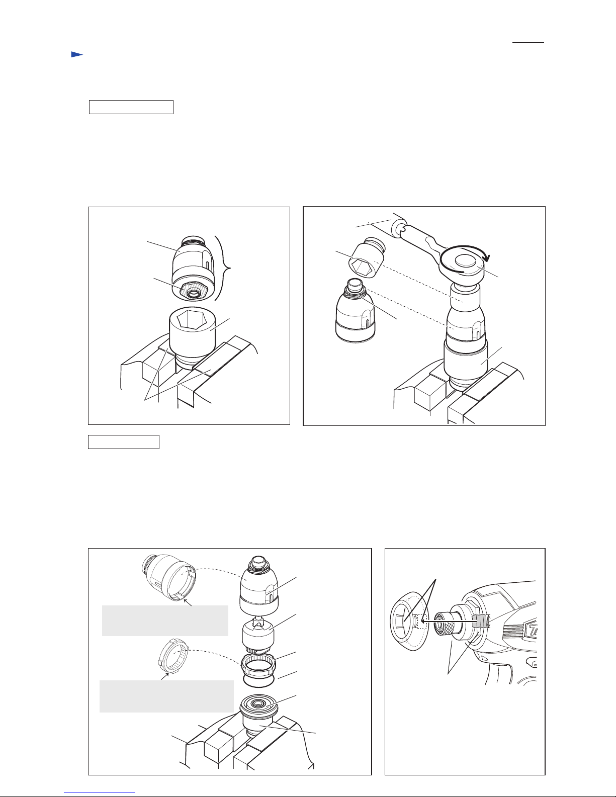
ASSEMBLING
Fig. 8
Fig. 9
Fig. 10 Fig. 11
(7) Hold 134848-9 with 1R041 in Vise, and then fit the hexagonal portion of Bearing box complete into 134848-9.
(Fig. 8)
(8) Set 1R224 and 134847-1 to 1R223, and then fit the hexagonal portion on Hammer case complete into 134847-1 and
turn 1R223 clockwise. (Fig. 9)
Note: Hammer case complete has a left hand thread.
(9) Hammer section can be disassembled as drawn Fig. 10.
(1) Reverse the disassembling steps of Hammer case complete, Hammering mechanism, Internal gear 51, O ring 40 and
Bearing box complete as drawn in Figs 10 and 9.
(2) Set 1R224 and 134847-1 to 1R223, and then fit the hexagonal portion on Hammer case complete into 134847-1 and
turn 1R223 counterclockwise.
Note: The fastening torque has to be 30N.m to 40N.m.
(3) Hook Hammer case cover to the hexagonal portion of Hammer case complete, and then fit its hooks to
the depressions on the reverse of Bumper.
P 4/ 11
Repair
Hexagonal
portion of
Bearing box
complete
Hexagonal
portion of
Hammer case
complete
134848-9
134848-9
134848-9
1R041
Hammer case
complete
Hammer
section
Bearing box
complete
Hammer case
complete
Hammering
mechanism
Internal gear 51
hooks of Hammer case
cover
depressions of Bumper
Fit the four projections of
Internal gear 51 into the grooves
of Hammer case complete.
Fit the stepped end of Internal
gear 51 into the groove of Bearing
box complete.
O ring 40
134847-1
1R223
1R224
 Loading...