

Makita LXDG01 1 Series, BGD800, LXDG01Z 1 Series, BGD801, BGD800Z Technical Information
...
T
ECHNICAL INFORMATION
Model No.
Description
BGD800 (LXDG01)*1, BGD801
Cordless Die Grinder
*1 Model number for North and Central American countries
CONCEPT AND MAIN APPLICATIONS
Models BGD800 (LXDG01)*1 and BGD801 are Cordless die grinders
powered by 18V/3.0A Li-ion battery BL1830, featuring the same
easy-to-grip slim motor housing as used for Model BGA402 Cordless
angle grinder.
BGD800 is a long-nose die grinder using the mechanical section of
Model GD601 while BGD801 is a short-nose type using that of
Model GD602.
Note: These models are not compatible with 1.3Ah Li-ion battery BL1815.
These new products are available in the following variations.
BGD800 (LXDG01)*1
Model No.
BGD800Z
(LXDG01Z)*1
BGD800RFE
(LXDG01)*1
BGD801
Model No.
BGD801Z
BGD801RFE
All models also include the accessories listed below in "Standard equipment".
Battery
Type Quantity
--- --- ------ ---
BL1830 DC18RA Yes
Battery
Type Quantity
---
BL1830
Battery
cover
2 1
Battery
cover
2 1
Charger
Charger
--- ------ ---
DC18RA Yes
Plastic
carrying case
Plastic
carrying case
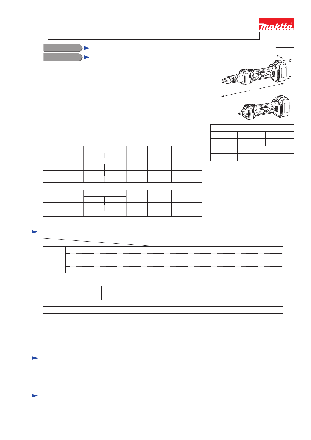
Dimensions: mm (")
Length (L)
Width (W)
Height (H)
PRODUCT
P 1/10
W
BGD800
H
L
BGD801
BGD800 BGD801
402 (15-3/4) 307 (12-1/8)
82 (3-1/4)
118 (4-5/8)
Specification
Specification
Cell
Battery
Max output: W 350
No load speed: min-1=rpm 25,000
Collet size: mm (")
Max collet capacity: mm (")
Max wheel diameter: mm (")
Weight according to
EPTA-Procedure 01/2003*4: kg (lbs)
*2: The tools for India additionally includes 8mm collet cone.
*3: 1/4" is the Max. collet capacity in inch for North American countries.
(Collet cone of inch size corresponding to 8mm is not available for these models.)
*4: with battery, collet cone and collet nut
Voltage: V
Capacity: Ah
Supplied with the tool
Option
Model
BGD800 BGD801
22 with DC18RACharging time (approx.): min.
6*2 (1/4)
3, 6, 8 (1/8, 1/4)
8 (1/4)*3
38 (1-1/2)
2.0 (4.4) 1.7 (3.8)
Standard equipment
Wrench 13 ............................................... 2
Collect cone 6mm or 1/4" ....................... 1
Collect cone 8mm ................................... 1 (for India)
Note: The standard equipment shown above may vary by country.
Li-ion
18
3.0
Optional accessories
Collet cones (3mm, 6mm, 8mm, 1/8", 1/4")
Side grip
Wheel points
Battery BL1830
Fast charger DC18RA
Charger DC18SD
Charger DC24SC
Automotive charger DC18SE
BGD0800 (LXDG01)
Repair
CAUTION: Repair the machine in accordance with “Instruction manual” or “Safety instructions”.
[1] NECESSARY REPAIRING TOOLS
Code No. Description Use for
1R279 Round bar for arbor 5-50 removing Armature
1R291 Retaining ring S and R pliers removing Retaining rings S-9 and S-12
1R350 Ring 60 holding Bearing box complete when removing Armature
1R382 Armature positioning jig
Hex socket bit 17 fixing Coupling when removing it from Spindle
Wrench 13 removing Spindle from Coupling
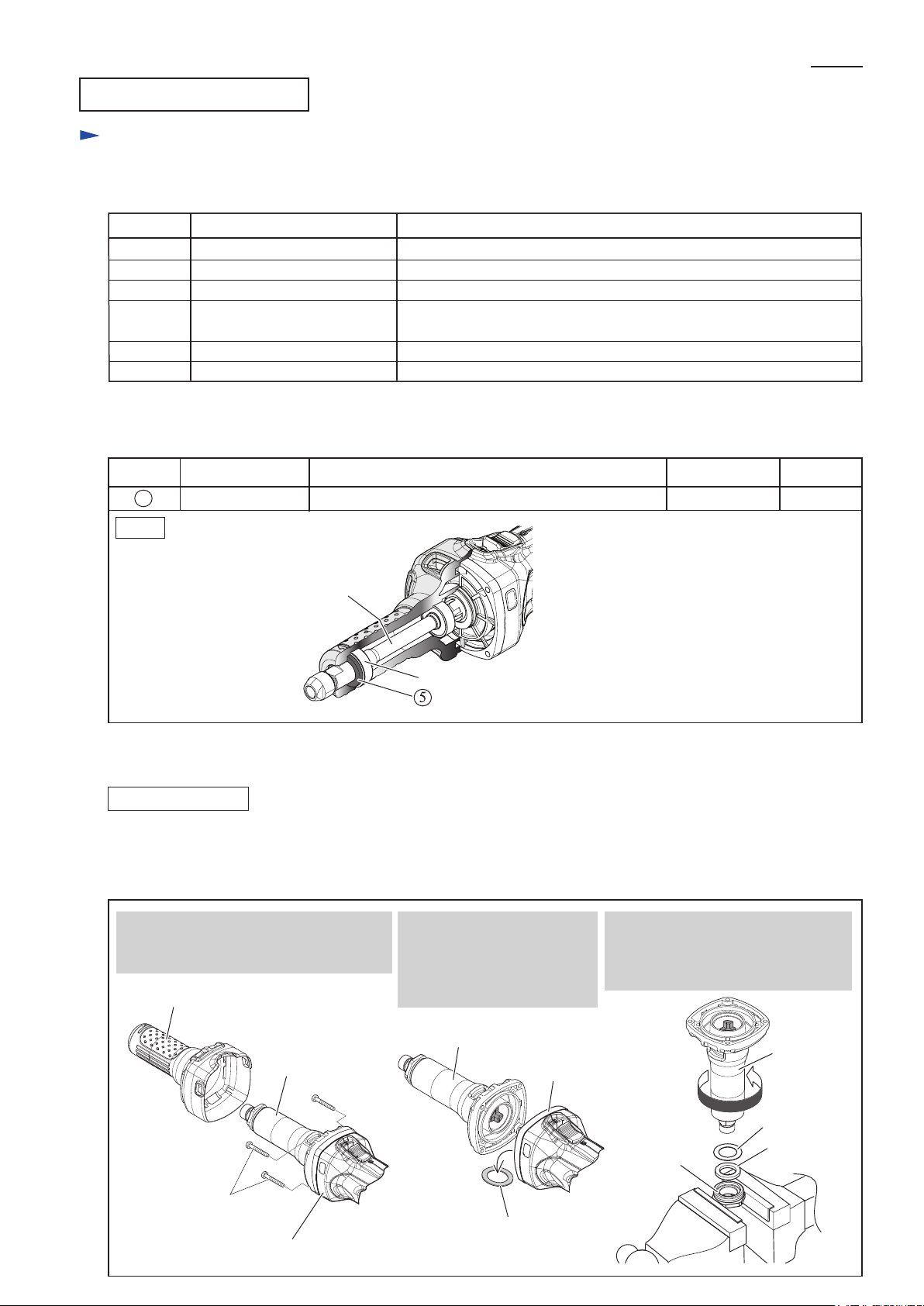
[2] LUBRICATION
Apply lubricant as instructed in the table below.
positioning Armature at the precise position when mounting it to
Bearing box complete
P 2/ 10
Item No.
5 Felt Ring 17 Apply sufficient lubricant to protect from dust.
Fig. 1
Description Lubricant Amount (g)Portion to lubricate
Spindle
Ball bearing 6001LLB
[3] DISASSEMBLY/ASSEMBLY
[3]-1. Coupling, Spindle
DISASSEMBLING
(1) Remove Collet cone and Collet sleeve from Spindle.
(2) Remove Insulation cover from Barrel section. Separate Barrel section from Housing,
then disassemble Barrel section using vise. (Fig.2)
Fig. 2
“VG100”
1. Remove Insulation cover from Barrel,
then remove four 4x30 Tapping screws
that fasten Barrel section to Housing.
Insulation cover
Barrel section
4x30 Tapping screw
(4 pcs)
Housing
2. Separate Barrel section
from Housing.
Note:
Be careful not to lose
Flat washer 22 in this step.
Barrel section
Housing
Flat washer 22
3. Fix Barrel section in vise securely,
then remove Bearing retainer from
Barrel complete by turning Barrel
complete counterclockwise.
Barrel
complete
Flat washer 18
Bearing
retainer
Felt ring
BGD0800 (LXDG01)
Repair
[3] DISASSEMBLY/ASSEMBLY
[3]-1. Coupling, Spindle
DISASSEMBLING
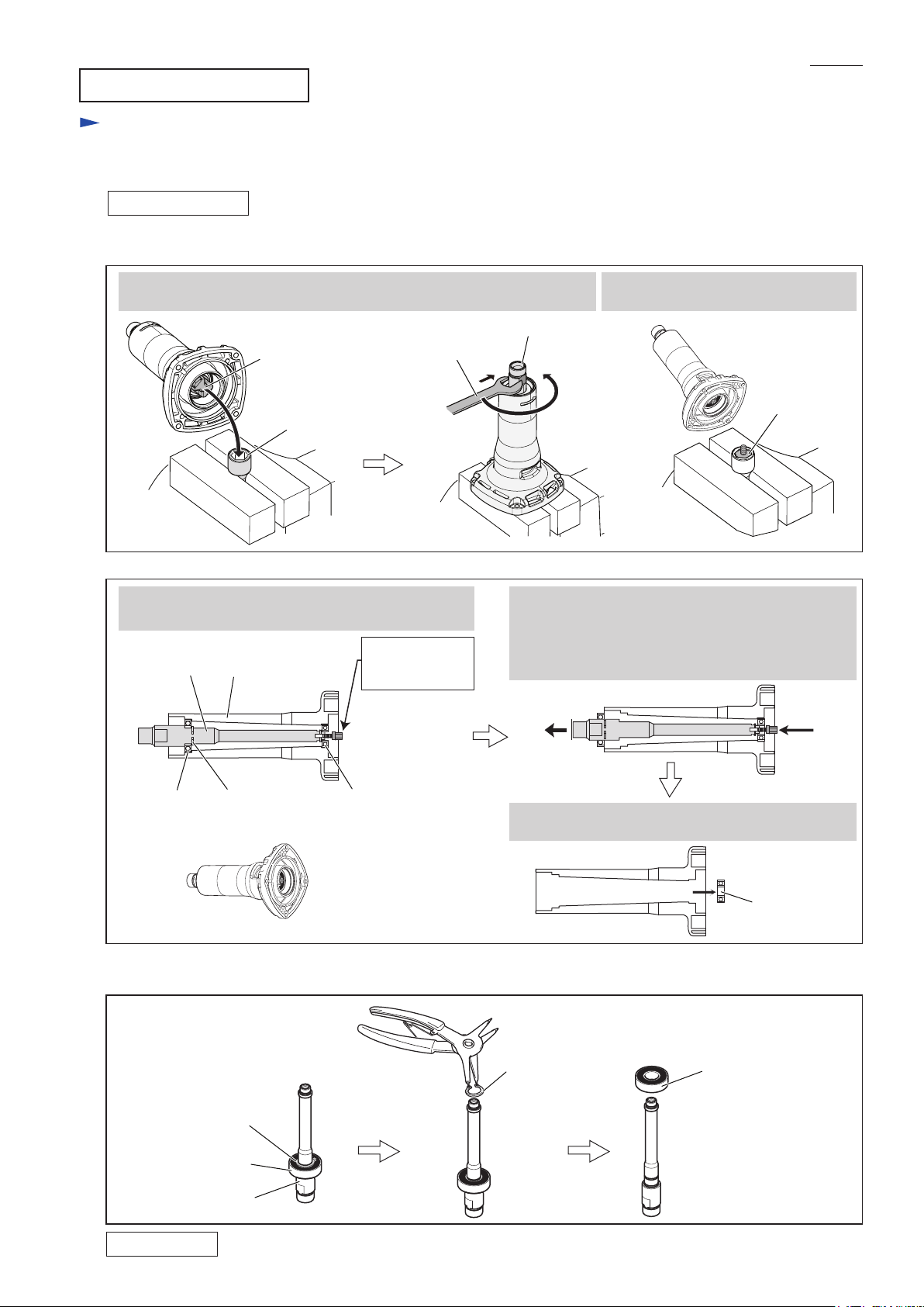
(2) Remove Coupling from Spindle, then separate Spindle from Barrel complete. (Figs. 3, 4)
Fig. 3
P 3/ 10
4. Turn Spindle counterclockwise with Wrench 13 while holding Coupling
with Hex box bit 17.
Spindle
Coupling
Hex socket
bit 17
Fig. 4
6. Drive the removed Coupling in Spindle again
about 2 pitches for utilizing it as a removing tool.
Spindle
Barrel complete
Wrench 13
Drive Coupling
about 2 pitches
in Spindle again.
7. Push Coupling by hand towards the front end of
Barrel complete, and remove Spindle together with
Ball bearing 6001LLB and Retaining ring S-12;
in this step, Ball bearing 629LLB remains in
Barrel complete.
5. The Coupling disconnected from
Spindle remains in Hex box bit 17.
Coupling
[front end]
Ball bearing
6001LLB
(3) Remove Retaining ring S-12 and Ball bearing 6001LLB from Spindle. (Fig. 5)
Fig. 5
Ball bearing
6001LLB
Retaining ring
S-12
[front end]
Retaining
ring S-12
Spindle
[rear end]
[rear end]
Ball bearing
629LLB
8. Remove Ball bearing 629LLB from the rear end of
Barrel complete.
Retaining
ring S-12
Ball bearing
6291LLB
Ball bearing
6001LLB
ASSEMBLING
Do the reverse of the disassembling steps.
 Loading...